LCN 4040SE Series Double Egress Installation Instructions 107120
Open the original PDF document
View PDF

4040SE DE Sentronic

24771 SE Double Egress
Installation Instructions
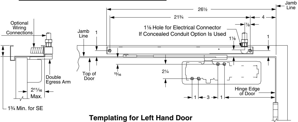
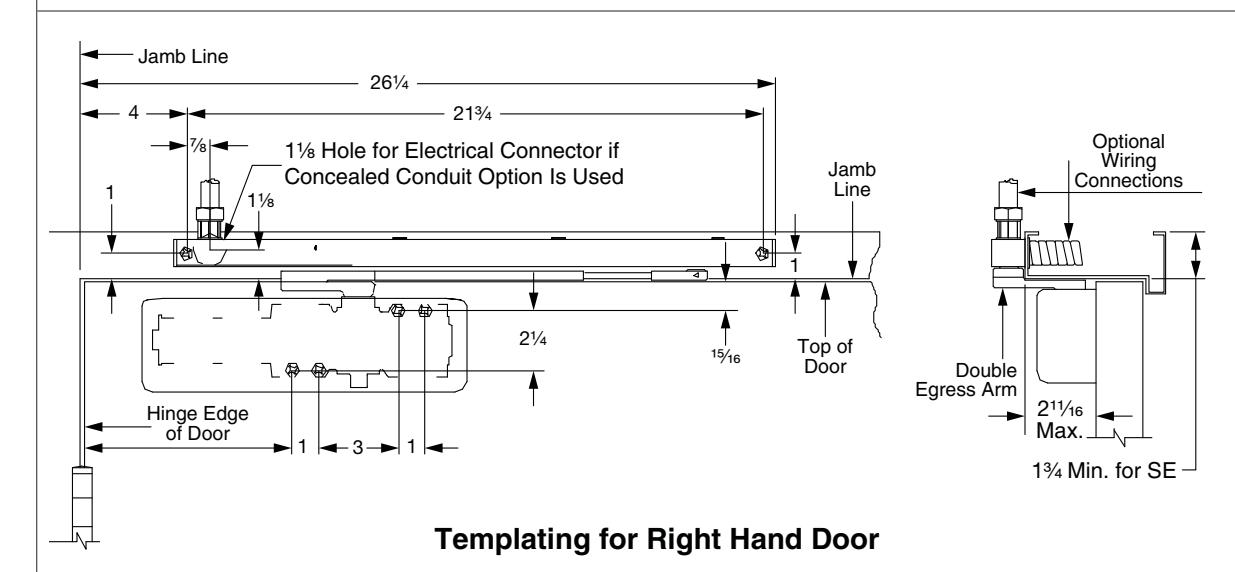
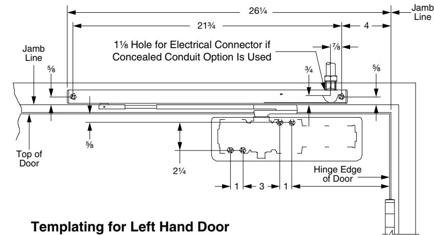
This closer features mounting options for both standard and step-down double egress frames. Before beginning, determine which type of mounting best applies to your application, or has been specified for the job, then be sure to use the proper template.
1 Voltage
The voltage shown on the track cover plate must match voltage supplied to door frame (24V or 120V). If concealed wiring is desired, prepare the frame to specifications shown on the corresponding template. If surface wiring is desired, be sure to mount the track on the frame before running any EMT/conduit.
2 Track
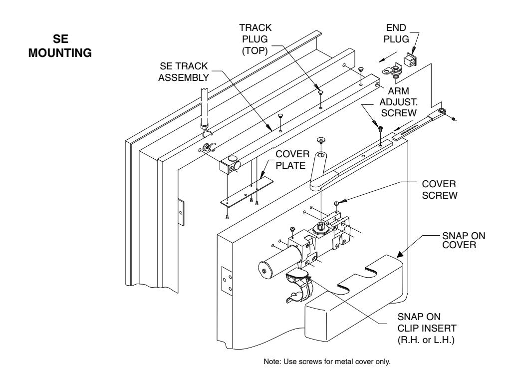
Insert the proper track plugs into the top of the track. Using the fasteners provided, mount the track on the frame to the template dimensions being used. Make the electrical connections (see page 2).
3 Spring Power
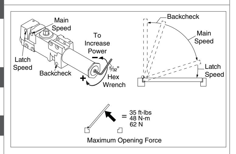
Before mounting closer, the spring power may need adjusting. Refer to the label on the closer spring tube. The 4040SE DE Series comes preset at size 3. This will control a door up to 38", adjust the closer as shown (see illustration to the right) up to 7 full turns. Starting the cover screws at this point is recommended. Using the fasteners provided, mount the closer on the door to the dimensions of the template being used.
4 Arm Installation
Install the arm as follows:
Rotate the arm from the door until flats in the arm hub line up with the first available flats of the shaft. Slide the arm hub onto the closer shaft. Insert the shaft screw and tighten securely.
5 Arm Screw
Loosen the set screw in the arm. Connect the arm to the track roller, and tighten the set screw firmly.
6 Door Position
To adjust the hold-open position of the door: Remove the screw in the adjustable arm, and open the door to the desired position. Reinsert the screw and tighten securely.
7 Regulation
Do not allow the door to slam into the frame. A "normal" closing time from a 90° position is 5 to 7 seconds, evenly divided between the Main and Latch Speed. If adjustments are needed, use a 3/32" hex wrench. To adjust the Main Speed, turn the regulating screw (see illustration) clockwise to slow the speed or c.c.w. to increase the speed. Latch Speed is adjusted in the same way. When adjusting, use the Backcheck the least amount necessary to slow the swing of the door sufficiently. To adjust the Backcheck, turn the regulating screw clockwise to increase the amount of force or c.c.w. to reduce the amount of force.
NOTE: Do not use an abrupt backcheck setting or expect the door closer to act as a stop!
8 Door Closer Cover
With regulation done, place the snap-on clip insert into the proper cutout, then the snap cover assembly onto the spring tube.
A CAUTION A
Improper installation or regulation may result in personal injury or property damage. Follow all instructions carefully. For questions, call LCN at 877-671-7011.
Conduit Quick Conductor
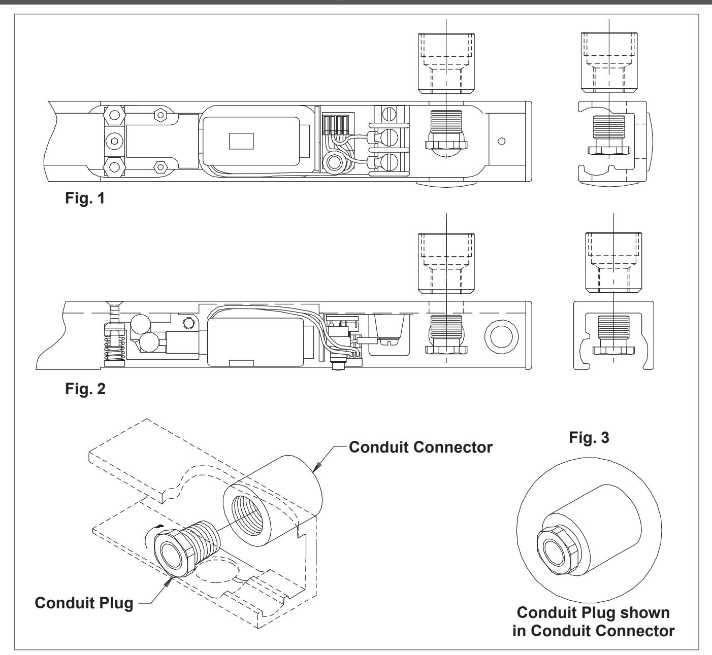
Installation Instructions
- 1a The Conduit Quick Connector and Plug can be found in the closer screwpack.
- 1b The Conduit Quick Connector should be fastened to the 1/2" concealed conduit prior to step 3 on the closer installation instructions.
- 1c During step 3 on the closer installation instructions, make sure that the Conduit Connector is secured flush against the track surface. See option in Fig. 1 below that matches the mounting option selected for track surface. With the track mounted, take the Conduit Plug and slide it through the 1/2" hole in the track. (see Fig.2) Tighten the Plug into the Conduit Connector using a 5/8" wrench, until completely secure, as shown in Fig.3.
A WARNING
Hazardous voltage can shock and cause severe injury!
Disconnect the power before making any electrical connections or performing maintenance.
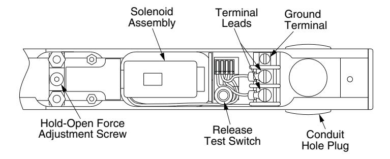
Hold-Open Force Adjustment:
Locate the hold-open adjustment screw in the diagram to the right. For greater hold-open force, insert a 3/32" hex wrench, and turn clockwise. To decrease the amount of hold-open force, turn the screw counterclockwise, for a maximum of 4 turns.
Electrical Checkout
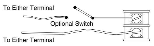
Wiring Diagram - Polarity Not Important
Input Voltage: 24v AC/DC Or 120v AC/DC (Usually From Alarm Panel or Detector)
- 1. With power on, open the door. The door should remain in the open position. If the door does not stay open, check the electrical output.
- 2. Push the release test switch. The door should close immediately. Open the door to the hold-open position and let it remain there.
- 3. The system should be checked at frequent intervals. It is suggested that Step 2 be repeated every 90 days.
A WARNING
HAZARDOUS VOLTAGE CAN SHOCK AND CAUSE SEVERE INJURY!
Disconnect the power before making any electrical connections or performing maintenance.
DOOR HOLDER SOLENOID DATA 24VAC - DC Nominal =10% - 15% @ .090 Amp. Max. 120 VAC - DC Nominal =10% - 15% @ .030 Amp Max.
4040SE DE Up To 95° Hold Open Auxiliary Stop Recommended
| Dim. | Reveal |
| 77/8 | 211/16 |
| 73/8 | 2 |
| 6¾ | 11/2 |
| 6½ | 1 |
| Dim. | Reveal |
| 77/8 | 211/16 |
| 73/8 | 2 |
| 63/4 | 1½ |
| 6½ | 1 |
Notes:
- 1. The voltage supplied must match the voltage shown on the Sentronic label.
- 2. If the door is hung on pivots or swing clear hinges, consult the factory.
- 3. Floor or wall stops must be used.
- 4. For 71/4" or less double egress frames, the reveal should not exceed 211/16".
- 5. The 1/8" door-to-Soffit clearance is required.
- 6. Reinforcing per ANSI/SDI-100 is recommended for hollow metal doors and frames.
- 7. The maximum butt hinge size is 5" x 5".
| Inch | 1/8 | 1/4 | 7/8 | 15/16 | 1 | 11/8 | 11/4 | 11/2 | 13/4 | 2 | 21/4 | 211/16 | 21/8 | 3 | 4 | 5 | 61/2 | 63/4 | 71/4 | 73/8 | 71/8 | 21¾ | 261/4 |
|---|---|---|---|---|---|---|---|---|---|---|---|---|---|---|---|---|---|---|---|---|---|---|---|
| M.M. | 3 | 6 | 22 | 24 | 25 | 29 | 32 | 38 | 44 | 51 | 57 | 68 | 73 | 76 | 102 | 127 | 165 | 171 | 184 | 187 | 200 | 552 | 667 |
4040SE-DE: For 5/8" Step-down frames
A WARNING A
HAZARDOUS VOLTAGE CAN SHOCK AND CAUSE SEVERE INJURY!
Disconnect the power before making any electrical connections or performing maintenance.
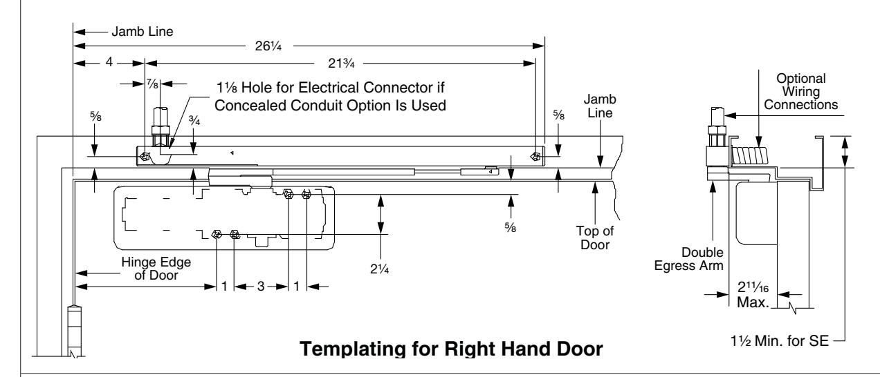
Optional Wiring Connections DOOR HOLDER SOLENOID DATA 24VAC - DC Nominal =10% - 15% @ .090 Amp. Max. 120 VAC - DC Nominal =10% - 15% @ .030 Amp Max.
Double Egress Arm
└ 1½ Min. for SE
4040SE DE Up To 95° Hold Open Auxiliary Stop Recommended
| Dim. | Reveal |
| 77/8 | 211/16 |
| 73/8 | 2 |
| 6¾ | 1½ |
| 6½ | 1 |
| Dim. | Reveal |
| 77/8 | 211/16 |
| 73/8 | 2 |
| 63/4 | 1½ |
| 61/2 | 1 |
Notes:
- 1. The voltage supplied must match the voltage shown on the Sentronic label.
- 2. If the door is hung on pivots or swing clear hinges, consult the factory.
- 3. Floor or wall stops must be used.
- 4. For 71/4" or less double egress frames, the reveal should not exceed 211/16".
- 5. The 1/8" door-to-Soffit clearance is required.
- 6. Reinforcing per ANSI/SDI-100 is recommended for hollow metal doors and frames.
- 7. The maximum butt hinge size is 5" x 5".
| Inch | 1/8 | 1/4 | 7/8 | 15 ⁄ 16 | 1 | 11/8 | 11/4 | 1½ | 1¾ | 2 | 21/4 | 211/16 | 27/8 | 3 | 4 | 5 | 6½ | 63/4 | 71/4 | 73/8 | 77/8 | 21¾ | 261/4 |
|---|---|---|---|---|---|---|---|---|---|---|---|---|---|---|---|---|---|---|---|---|---|---|---|
| M.M. | 3 | 6 | 22 | 24 | 25 | 29 | 32 | 38 | 44 | 51 | 57 | 68 | 73 | 76 | 102 | 127 | 165 | 171 | 184 | 187 | 200 | 552 | 667 |