LCN 2010 Series Installation Instructions 106933
Open the original PDF document
View PDF

18755
2010 Series

Installation Instructions
Instructions
- Make sure hand of closer and door correspond. Hand of closer is stamped on finish plate. Hand of closer can not be reversed.
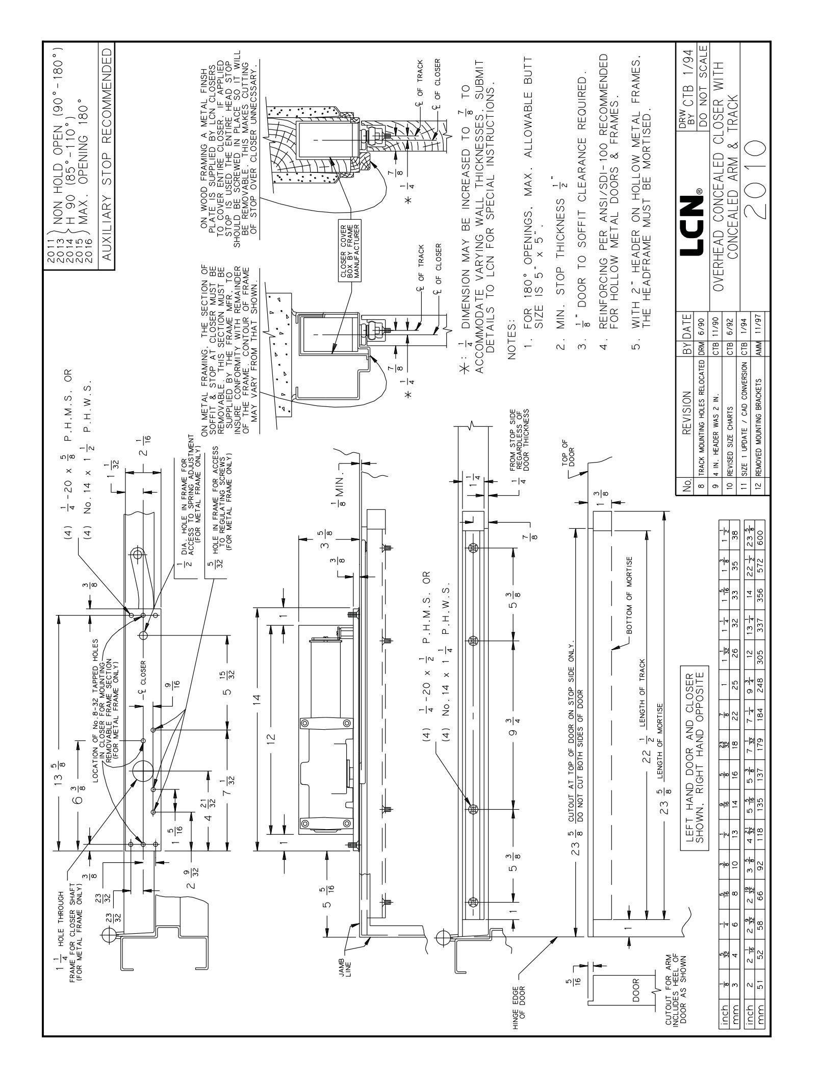
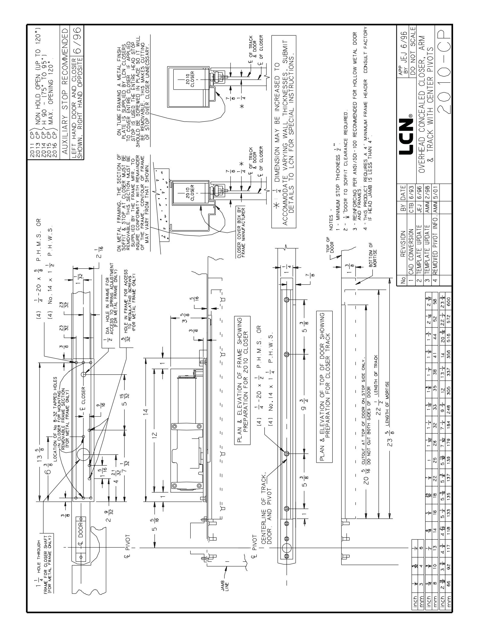
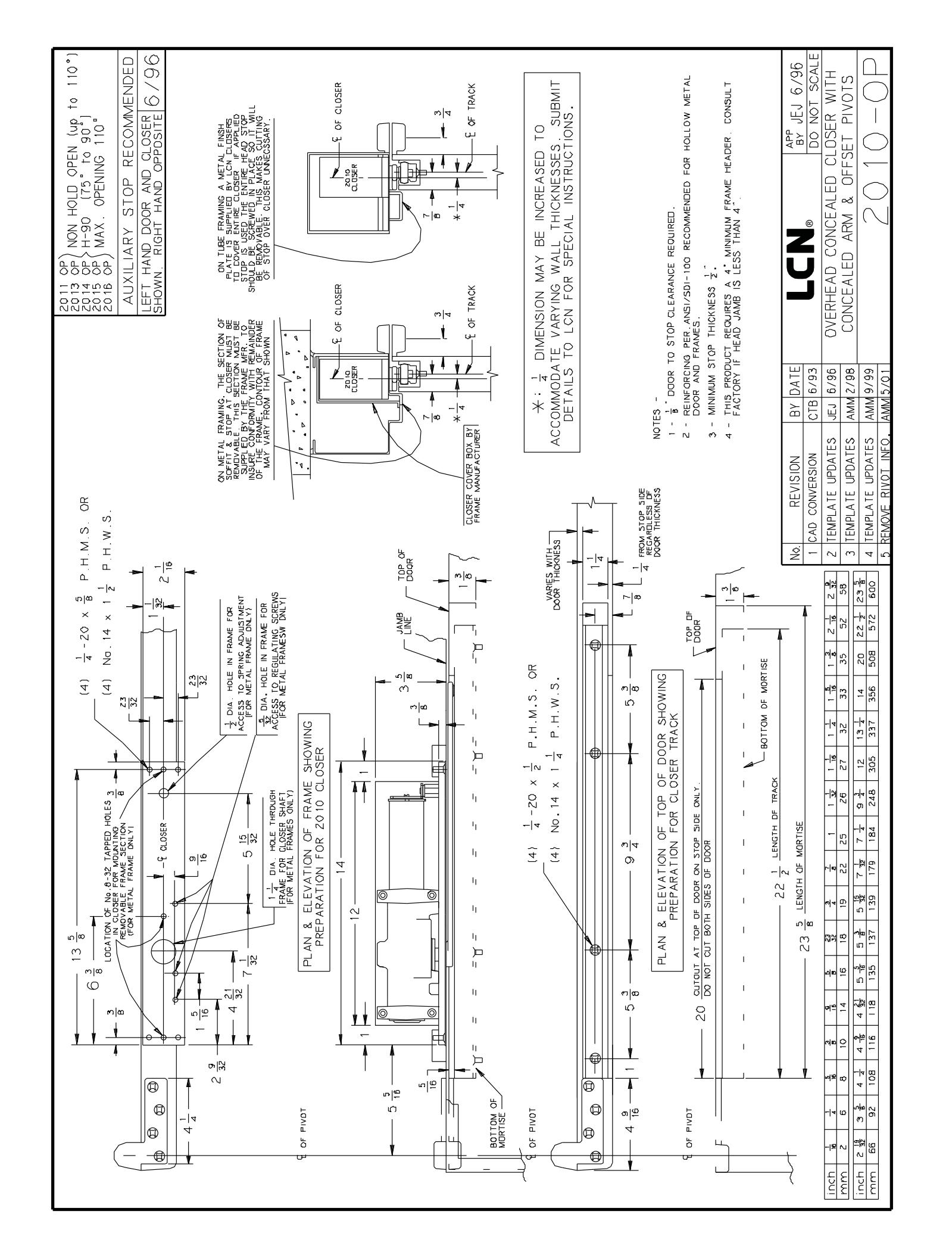
- If door and frame are not prepared for closer and track, prepare to dimensions shown on other side.
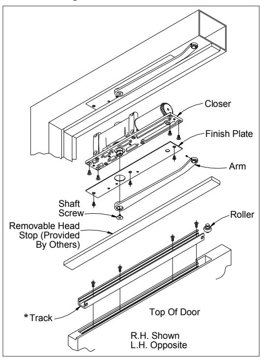
- Install closer in prepared frame with proper screws. Replace finish plate (or frame plate provided by frame manufacturer) and be sure plate is flush with soffit. Place arm on closer shaft and secure with shaft screw. Insert track roller in track. Install track level in door.
- 4. Hang door on butts. Be sure there is no bind or friction. Open door 45° and pull arm away from stop. Using allen wrench furnished, back out arm set screw to clear arm roller stud. DO NOT DRIVE ARM DOWN OVER ROLLER STUD. Lift end of arm up and over roller and gently fit roller stud into arm. Tighten self locking set screw.
A CAUTION A
Improper installation or regulation may result in personal injury or property damage. Follow all instructions carefully. For questions, call LCN at 877-671-7011
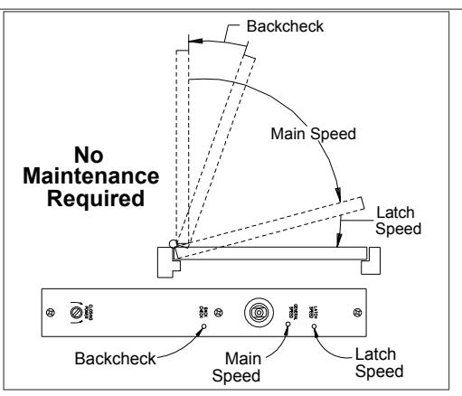
- 5. IMPORTANT: Closer has been regulated prior to shipment. Adjust regulation only if necessary. Use a 3/32" hex wrench and to adjust speed (see illustration). To slow main speed of door, turn regulating screw nearest shaft clockwise. To slow latch speed of door, turn regulating screw nearest hinge clockwise. BACKCHECK To increase backcheck intensity, turn regulating screw nearest latch clockwise.
- ① Do not use abrupt backcheck- nor expect door closer to act as a door stop.
Customer Service 1-877-671-7011 www.allegion.com/us
Adjust CLOSING POWER only if more power is needed. Closer is shipped with minimum closing power preset. To increase CLOSING POWER turn spring adjusting screw clockwise. Maximum adjustment is 18 turns.
| Table of Sizes | ||
|---|---|---|
| Maximum | ||
| Exterior Doors | Interior Doors | Catalog No. of Closers |
| Ŀ. | 2011 | |
| 30 (765 mm) | 38 (965 mm) | 2013 |
| 36 (915 mm) | 48 (1220 mm) | 2014 |
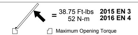
| 42 (1065 mm) | 54 (1370 mm) | 2015 |
| 48 (1220 mm) | 60 (1525 mm) | 2016 |
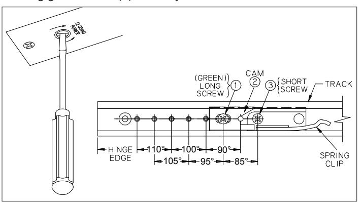
7. HOLD OPEN ADJUSTMENT: Change the hold open position by removing screws (1) and then (3). Locate to required position as shown. (See illustration for hold-open spring clip position.) Install screw (3) securely. Tip cam (2) into track and locate as shown. Install long green screw (1) securely. Push door into hold open position. For INCREASED HOLDING POWER, loosen long green screw (1), slide cam (2) TOWARD LATCH, retighten long green screw (1) securely. For DECREASED HOLDING POWER, loosen long green screw (1), slide cam (2) TOWARD HINGE edge of door, retighten long green screw (1) securely.

© Allegion 2014 Printed in U.S.A. 18755 Rev. 01/14-i
BEGINNING SHEET
| Additional Notes: | |
|---|---|
| 1. None | |
| Revision History | Revision Description: | |||||||||
|---|---|---|---|---|---|---|---|---|---|---|
| J | K | L | М | N | Р | J > Revised artwork | ||||
| 043228 | ] | |||||||||
| Material White Paper | Edited By | Approved By | EC Number | Release Date | ||||||
| D. Myers | M. Sasso | 043228 | 01-01-14 | |||||||
| Notes |
Notes
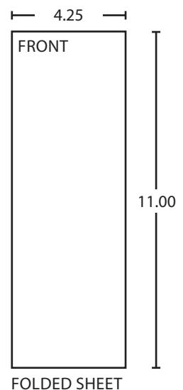
1. printed two sides 2. printed black |
Title | ||||||||
| • | 2010 Series Instruction Sheet | |||||||||
| 3. tolerance ± .13 | Creation Date | Number | Revision | |||||||
|
4. printed in country may vary
5. drawings not to scale |
05-10-10 | 18755 | J | |||||||
| o. Grawings not to scale |
Created By
N/A |
Activity
3899 Hancock Expwy |
||||||||
| Software: InDesign CS6 | Security, CO 80911 | © Allegion 2014 | ||||||||