LCN 1250 and 1450 Series Section Catalog 110655
Open the original PDF document
View PDF1250 & 1450 SERIES SURFACE MOUNTED CLOSERS
PRODUCT SELECTION GUIDE
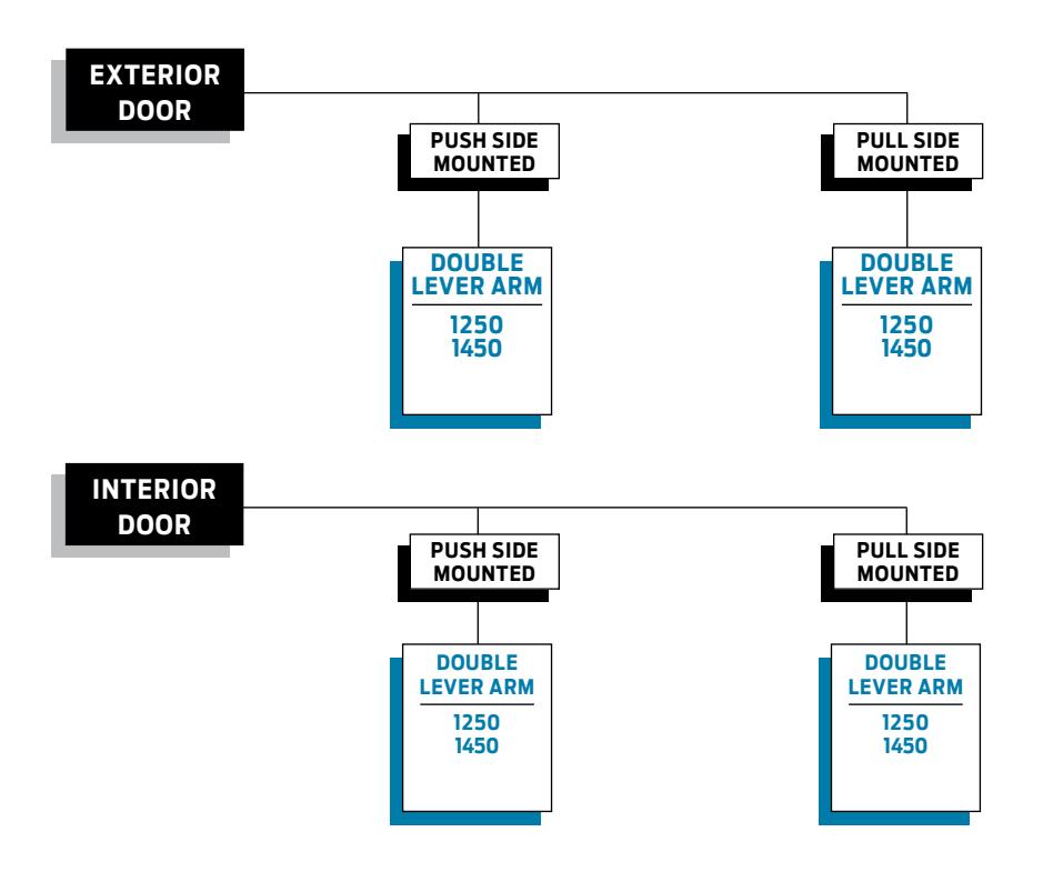
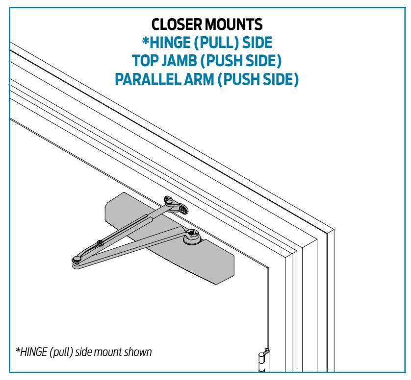
Surface mounted 1250 & 1450 Series LCN closers feature a modern slim line design for easy installation on narrow head frames and top rails. This guide is based on the desired mounting of the closer.
PRODUCT COMPARISON
This chart shows a basic comparison of LCN 1000 Series closers. Refer to the specific closer chapter for complete details.

AVAILABLENOT AVAILABLE

& amp; Closer available with less than 5.0 lbs. opening force on 36" door.
* Maximum opening/hold-open point with standard template. See individual closer series for degrees of opening per installation.
1250 & 1450 SERIES SURFACE MOUNTED CLOSERS
APPLICATIONS
- n For aluminum, hollow metal, or wood swinging doors and frames.
- n Can be used with hinge or pivot mounted door.
- n Mounts on 1-3/4" transom without adapter plates.
- n Adapter plates and other installation accessories available for unusual conditions.
FEATURES COMMON TO 1000 SERIES
- n 1000 series closers mount three ways. Closers with regular or hold-open arm mount hinge side or top jamb. Parallel arm, closers include - 62PA SHOE required for parallel arm mount.
- n Non-handed for right and left swinging doors.
- n Closers to meet ADA reduced opening force requirements.
- n Adjustable hydraulic backcheck cushions opening swing prior to 90°.
- n Separate regulation of general closing speed and latching speed.
- n Joints in arm and shoe adapt to uneven trim.
- n Reversible shoe to boost latching power on double lever arms.
DESIGN ASSISTANCE
LCN has been providing reliable solutions to unique door control problems for over 85 years. Design and specification assistance are only a phone call away.
Contact LCN for assistance or technical information at 877-671-7011 or FAX 800-248-1460 (Order Entry) , Fax 815-879-1495 for Product Support.
WARRANTY
15 year limited warranty (1250 series) and 25 year limited warranty (1450 series) on cast aluminum. See General Information Section for complete warranty details.
SPECIFICATIONS
Refer to "SPECIFICATIONS" section for suggested architectural specifications.
MATERIALS
- n High strength cast aluminum cylinder.
- n Forged steel main arm for all EDA, Cush, and SCUSH.
- n Heat treated pinion.
- n All weather fluid for cast aluminum performs to -30 degrees.
- n High efficiency , full complement , low friction bearings.
- n Tamper resistant regulating screws.
- n Full rack and pinion hydraulic action.
FINISHES
- n Painted finishes on cast aluminum.
- n Available in six standard or a wide selection of optional custom powder coat finishes to blend with door and frame.
- n LCN's powder coat finish surpasses 100 hours of salt spray which is over four times the ANSI standard for corrosion resistance.
- n For installations where a higher level of corrosion resistance is required, LCN offers an optional special rust inhibiting (SRI) pre-treatment. Closers that combine the exclusive LCN powder coat finish and the SRI pre-treatment exceed the ANSI standard for corrosion resistance even further.
- n Plated finishes are available as an option to accent door and frame for the 1450 Series closers.
LISTINGS & APPROVALS
UL listed for self-closing doors without hold-open under "SWINGING DOOR CLOSERS" (GVEV). Tested and certified under ANSI Standard A156.4 grade one. Consult factory for details.
POSITIVE PRESSURE

LCN closers have been certified for three hours by UL to be in compliance with UBC 7-2 (1997) and UL 10 C. Contact LCN for specific details on door closer fire ratings.
FASTENERS
1250 and 1450 series closers are shipped with: A universal screw pack to include self reaming and tapping screws (SRT), machine screws and wood screws. Standard LCN thru bolts (TB) can be installed on 1-3/4" (44 mm) thick doors with 1/4-20 machine screws. Optional thru bolt (TB) sizes are available for 1-5/8" (41 mm) or 1-3/8" (35 mm) door thickness, but this
must be specified when ordering.
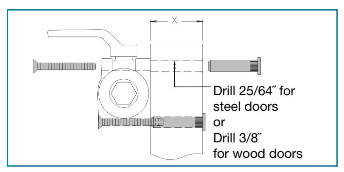
Note 1: For Thru Bolts, specify door thickness if other than 1-3/4" (44 mm). Represented in diagram as dimension "X".
Note 2: Phillips head, metric machine screws are available, please specify.
Note 3: LCN recommends the use of wood screws in wood door applications.
MAINTENANCE
Closers mounted according to LCN installation instructions require no periodic maintenance.

- Standard 1250 Series closer shipped with tri-pack arms: regular, parallel and top jamb, universal screw pack: self-reaming and tapping: 1-3/4" thru bolts; machine screws and wood screws. Optional Torx security and long thru bolts.
- Non-sized (1-5) cylinder is adjustable for interior doors to 4'6" and exterior doors to 3'6".
- Closer mounts hinge side, top jamb and parallel arm on either right or left swinging doors.
- Mounts to most common commercial footprint (3/4" x 9-1/16").
- Closer meets ADA requirements. See 1250 Series page 10 for chart.
- Optional SRI primer for installations in corrosive conditions.
- Optional slim line plastic cover.
- Tested and certified under ANSI Standard A156.4, grade one.
The 1250 Series cast aluminum closer is designed for low-frequency and low abusive traffic areas. This cast aluminum closer is ideal for aluminum storefronts, interior offices and many other applications. Combining dependable operation, low maintenance and a patented stylish look - with or without the optional slim line cover. And with the most common hole pattern in the industry, the 1250 Series is the perfect choice for easy aftermarket replacement.
- Cast Aluminum
- All weather fluid
- Non-handed
- Peel-n-stick templates for fast and accurate installation
- UL and cUL listed
- Adjustable spring size 1-5
- 15 Year Warranty
- Patent pending design

- Closer available with less than 5.0 lbs. opening force on 36" door.
- * Maximum opening/hold-open point with standard template, when conditions allow.

HINGE (PULL) SIDE MOUNTING
MAXIMUM OPENING
To 100°
- A = 6-11/16" (170mm)
- B = 12-7/16" (316 mm)
or 101° to 120°
- A = 5-11/16" (144mm)
- B = 11-7/16" (291 mm)
or *121° to 180°
- A = 3-3/16" (81mm)
- B = 8-15/16" (227 mm)
Hold-open points up to maximum opening with hold-open arm.
*Frame and trim permitting.
Options
- n Hold-open arm.
- n Slim Line cover (SLIM).
Special Templates
Customized installation templates or products may be available to solve unusual applications. Contact LCN Product Support for assistance.
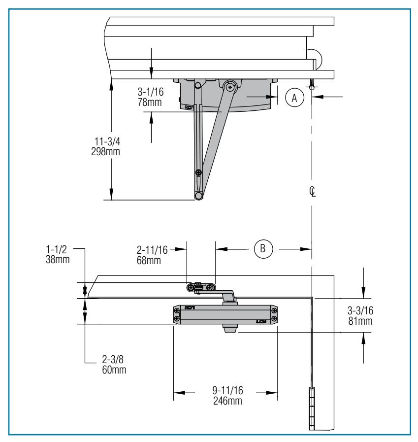
The 'A' dimension refers to the edge of the closer body to the center line of pivot or hinge. The 'B' dimension refers to the edge of the closer shoe bracket to the center line of pivot or hinge.
- n Butt Hinges should not exceed 5" (127 mm) in width.
- n Auxiliary Stop is recommended at hold-open point or where a door cannot swing 180°.
- n Reveal should not exceed 3/4" (19 mm) for regular arm or 1/2" (13 mm) for hold-open arm.
- n Top Rail less than 2-3/8" (60mm) requires PLATE, 1250-18.
- n Clearance of 3-1/16" (78mm) behind door required for installation.

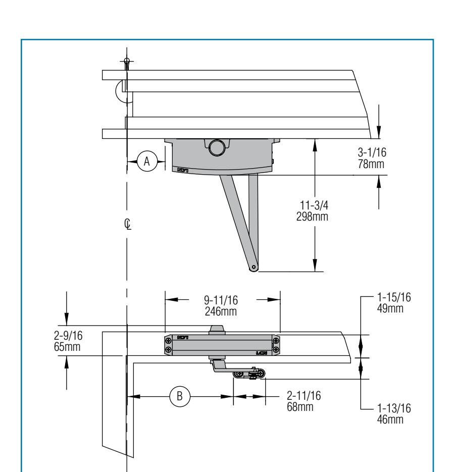
The 'A' dimension refers to the edge of the closer body to the center line of pivot or hinge. The 'B' dimension refers to the edge of the closer shoe bracket to the center line of pivot or hinge.
- Butt Hinges should not exceed 5" (127 mm) in width.
- Auxiliary Stop is recommended at hold-open point or where a door cannot swing 180°.
■ Reveal
| Arm Type | Reveal | Max. Opening |
|---|---|---|
| Regular | 0" to 5" | 180° |
| Long | 4" to 8" | 165° |
| Hold-Open | 0" to 2-3/4" | 1800 |
| Long Hold-Open | 2" to 6-1/2" | 180° |
- Top Rail requires 1-3/4" (44 mm) minimum. 2-1/2" (64 mm) minimum with closer on PLATE, 1250-18.
- Head Frame less than 1-3/4" (44 mm) requires PLATE, 1250-18. For flush ceiling condition with 2" (51 mm) headframe, use PLATE, 1250-18. (Plate requires 1-3/8" (35 mm) minimum.)
TOP JAMB (PUSH SIDE) MOUNTING
MAXIMUM OPENING
To 100°
- = 7-3/16" (183mm)
- (B) = 12-15/16" (329 mm)
-
or 101° to 120°
- = 5-11/16" (144mm)
- (B) = 11-7/16" (291 mm)
-
or *121° to 180°
- = 3-3/16" (81mm)
- (B) = 8-15/16" (227 mm)
Hold-open points up to maximum opening with hold-open arm.
*Frame and trim permitting.
Options
- Long arm, hold-open arm.
- Long hold-open arm.
- Slim Line cover (SLIM).
Special Templates

PARALLEL ARM (PUSH SIDE) MOUNTING
Optional mounting requires PA SHOE, 1250-62PA for REGULAR or HOLD-OPEN arms. 1250 Parallel arm closer includes 1250-201 FIFTH HOLE SPACER to support PA SHOE.
MAXIMUM OPENING
Regular or hold-open arm can be templated to 100°
- A = 7-5/16" (186mm)
- B = 8-5/8" (219 mm)
- or 101° to 130°
- A = 5-13/16" (148mm)
- B = 7-1/8" (181 mm)
-
or *131° to 180°
- A = 3-13/16" (97mm)
- B = 5-1/8" (130 mm)
Hold-open points up to maximum opening with hold-open arm.
*Frame and trim permitting.
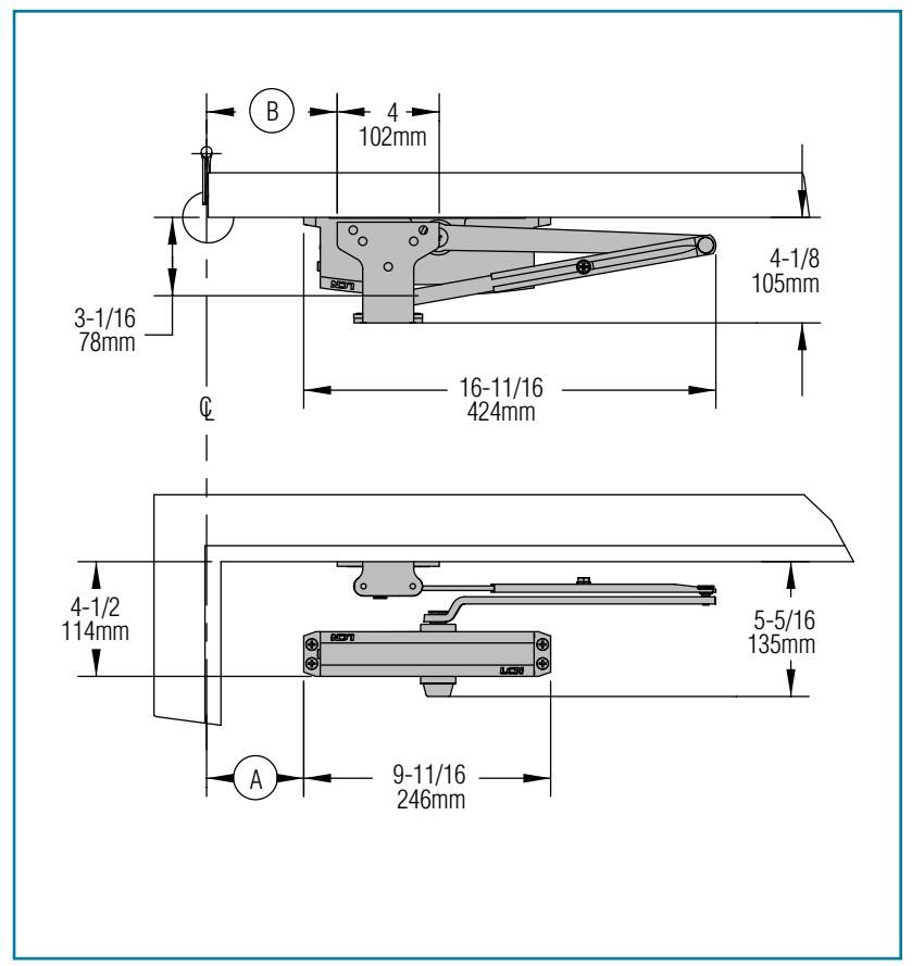
The 'A' dimension refers to the edge of the closer body to the center line of pivot or hinge. The 'B' dimension refers to the edge of the closer shoe bracket to the center line of pivot or hinge.
1250 REGULAR or HOLD-OPEN MOUNT
- n Butt Hinges should not exceed 5" (127 mm) in width.
- n Auxiliary Stop is recommended at hold-open point, where a door cannot swing 180°, or where CUSH-N-STOP arm is not used.
- n Clearance for 1250-62PA shoe is 4-1/8" (105mm) from door face.
- n Top Rail less than 4-1/2" (114mm) measured from the stop requires PLATE, 1250-18PA.
- n Stop Width minimum 1" (25 mm).
- n Blade Stop clearance, requires 1/2" (13 mm) BLADE STOP SPACER, 1250-61.
- n Auxiliary Shoe, 1250-62A allows installation of regular arm with overhead holder/stop.
- n Slim Line cover (SLIM).
- n Hold-open PA, HEDA, EDA, CUSH, HCUSH, SCUSH, SHCUSH arm.
Special Templates

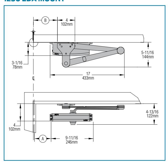
1250 EDA MOUNT
1250 CUSH /SCUSH MOUNT
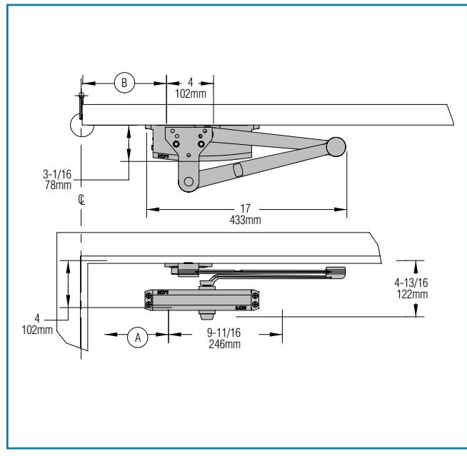
The 'A' dimension refers to the edge of the closer body to the center line of pivot or hinge. The 'B' dimension refers to the edge of the closer shoe bracket to the center line of pivot or hinge.
- Clearance for 1250-62EDA or CUSH shoe is 5-11/16" (144mm) from door face.
- Head Frame flush or rabbeted requires CUSH FLUSH PANEL ADAPTER, 1250-419.
- EDA or CUSH ARM requires soffit SHOE SUPPORT, 1250-30 for fifth screw anchorage where reveal is less than 2-3/4" (70mm).
- Spring CUSH hold open points are approximately 5º less than dead stop point.
1250 EDA OR CUSH-N-STOP MOUNTING
1250 closers ordered with EDA, CUSH or SPRING CUSH arms include 1250-201 FIFTH HOLE SPACER to support the shoe.
MAXIMUM OPENING
EDA template allows 180°. Hold-open point up to maximum opening. 100°.
- = 7-5/16" (186mm)
- B = 9" (229mm)
or 130°,
- = 5-13/16" (148mm)
- (B) = 7-1/2" (191mm)
or 180°,
- = 3-13/16" (97 mm)
- (B) = 5-1/2" (140 mm)
CUSH arms can be templated for maximum opening/hold-open point at 85°.
- = 8-13/16" (224 mm)
- (B) = 10-1/2" (267 mm)
900
- = 8-1/16" (205 mm)
- (B) = 9-3/4" (248 mm)
950,
- = 7-5/16" (186 mm)
- (B) = 9'' (229 mm)
1000,
- = 6-11/16" (170 mm)
- (B) = 8-3/8" (213 mm)
or 105°.
- = 6-1/16" (154 mm)
- (B) = 7-3/4" (197 mm)
or 110°.
- = 5-7/16" (138 mm)
- (181 mm)
CYLINDERS
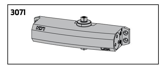
CYLINDER, 1250-3071
Standard, non-handed cast aluminum cylinder assembly.
ARMS
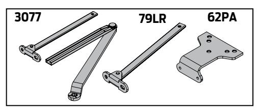
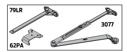
REGULAR ARM, 1250-3077
Non-handed arm mounts hinge side or top jamb. Parallel Arm includes PA SHOE, 1250-62PA required for parallel arm mounting.
PA SHOE, 1250-62PA
Required for parallel arm mounting.
LONG ARM, 1250-3077L
Optional, non-handed arm includes LONG ROD AND SHOE, 1250-79LR for top jamb mount with deep reveals.
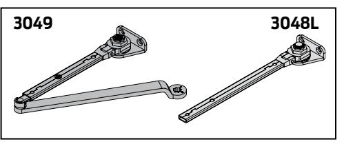
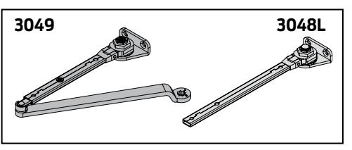
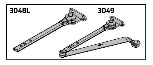
HOLD-OPEN ARM, 1250-3049
Optional, non-handed arm mounts hinge side, top jamb or parallel arm (62PA required). Hold-open adjustable at shoe.
LONG HOLD-OPEN ARM, 1250-3049L
Optional non-handed arm includes LONG HEAD AND TUBE, 1250-3048L for top jamb mount with deep reveals.
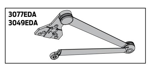
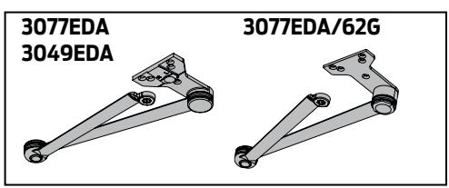
EXTRA DUTY ARM, 1250-3077EDA, 1250-3077EDA/G,
Optional, non-handed parallel arm features solid forged steel main and forearm for potentially abusive installations. Optional 1250-3077EDA/G for blade stop clearance.
HEDA ARM, 1250-3049EDA
Optional handed arm, provides hold-open function adjustable at shoe.
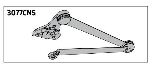
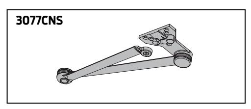
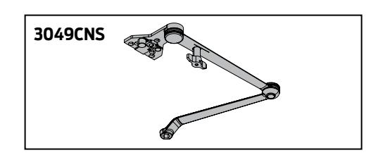
CUSH-N-STOP® ARM, 1250-3077CNS
Optional, non-handed parallel arm features solid forged steel main arm and forearm with stop in soffit shoe.
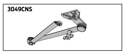
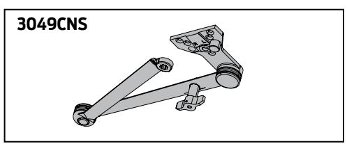
HCUSH ARM, 1250-3049CNS
Optional non-handed arm, provides hold-open function with templated stop/hold-open points. Handle controls hold-open function.
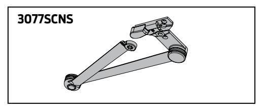
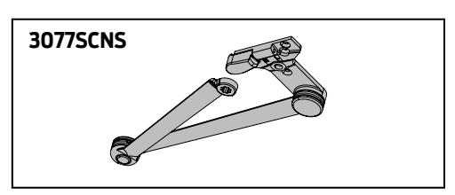
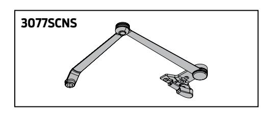
Spring Cush Arm, 1250-3077SCNS
Optional, non-handed parallel arm for abusive applications features solid forged steel main arm and forearm with spring loaded stop in the soffit shoe. Spring CUSH Arm hold open points are approximately 5° less than dead stop point.
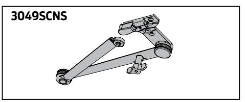
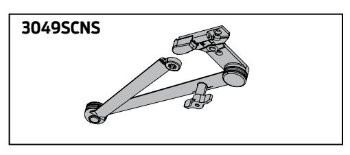
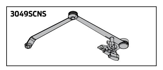
Spring HCush Arm, 1250-3049SCNS
Optional, non-handed parallel arm for abusive applications features solid forged steel main arm and forearm with spring loaded stop in the soffit shoe. Handle controls hold-open function.

COVER
COVER, 1250-72
Optional, non-handed, slim line plastic cover.
INSTALLATION ACCESSORIES
PLATE, 1250-18
Required for hinge side mount where top rail is less than 2-3/8" (60mm).
Required for top jamb mounting where head frame is less than 1-3/4" (44 mm) or flush ceiling condition exists. Plate requires minimum 1-1/2" (38 mm) minimum top rail or
PLATE, 1250-18PA
1-1/4" (32 mm) head frame.
Required for parallel arm mounting where top rail is less than 4-1/2" (114mm), measured from the stop. Plate requires 1-3/4" (44 mm) minimum top rail.
CUSH SHOE SUPPORT, 1250-30
Provide anchorage for fifth screw used with CUSH arms where reveal is less than 2-3/4" (70mm).
BLADE STOP SPACER, 1250-61
Lowers parallel arm shoe to clear 1/2" (13 mm) blade stop.
AUXILIARY SHOE, 1250-62A
Requires a top rail of 7-1/8" (181mm). Optional shoe replaces -62PA for parallel arm mounting of regular arm with overhead holder/stop.
FLUSH PANEL ADAPTER, 1250-419
Provides horizontal mounting surface for PA, EDA or CUSH shoe on single rabbeted or flush frame.
1250 SERIES
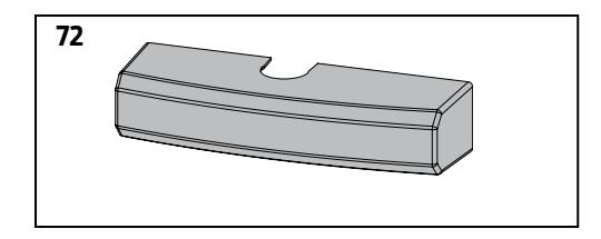
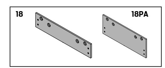
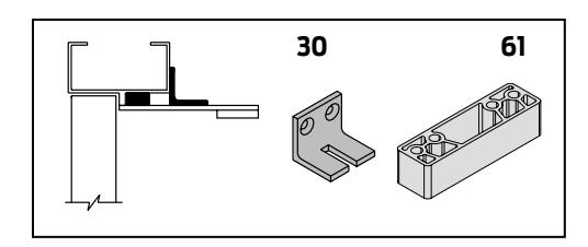
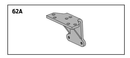
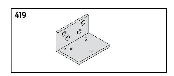

TABLE OF SIZES
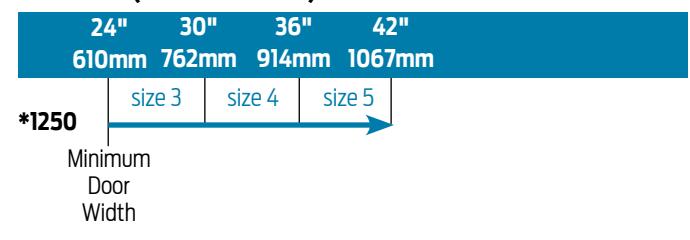
Select closer based on width of door.
The spring power of a 1250 cylinder is field adjustable from size 1 through size 5 and is shipped adjusted to size 3.
EXTERIOR (and VESTIBULE) DOOR WIDTH
INTERIOR DOOR WIDTH
|
24"
610mm |
34"
864mm |
38"
965mm |
48"
1219mm |
54"
1372mm |
|
|---|---|---|---|---|---|
| *1250 | size 2 | size 3 | size 4 | size 5 | |
|
Minimum
Door Width |
* Adjustable Size 1 thru 5 |
Indicates recommended range of door width for closer size.
REDUCED OPENING FORCE 1250 CLOSERS
CAUTION ! Any manual door closer, including those certified by BHMA to conform to ANSI Standard A156.4, that is selected, installed and adjusted based on ADA or other reduced opening force requirements may not provide sufficient power to reliably close and latch a door.
Refer to POWER OPERATORS section for information on systems that meet reduced opening force requirements without affecting closing power.
| DOOR WIDTH | 36" | 42" | 48" |
|---|---|---|---|
| 8.5* lbs. | 1250 | 1250 | 1250 |
| 5.0* lbs. | 1250 | 1250 | 1250 |
* Maximum opening force.
HOW-TO-ORDER 1250 SERIES CLOSERS
1. SELECT FINISH
Standard Powder Coat __________ Aluminum, Dark Bronze, Statuary, Light Bronze, Black, Brass.
Closer will be shipped with:
- STANDARD CYLINDER
- STANDARD COVER
- TRI PACK ARM
- UNIVERSAL SCREW PACK unless options listed below are selected.
CLOSER OPTIONS
COVER
Slim line cover (SLIM)
FINISH
Custom RAL___
SRI primer
ARM SCUSH / HCUSH
Regular w/62PA (Rw/PA)
Long (LONG)
Regular w/62A (R/62A)
Hold-Open w/62PA (Hw/PA)
Long Hold-Open (HLONG)
HEDA (specify right or left hand),
Cush-N-Stop (CUSH)
HCush (HCUSH)
Spring CUSH (SCUSH)
Spring HCUSH (SHCUSH)
EDA
SPECIAL TEMPLATE
ST- _________
OPTIONAL SCREW PACKS
TORX Machine Screw (TORX)
TB* & TORX Machine Screw (TBTORX)
* Specify door thickness if other than 1-3/4".
MEETS BUY AMERICAN ACT
BAA
INSTALLATION ACCESSORIES
Plate, 1250-18
Plate, 1250-18PA
CUSH Shoe Support, 1250-30
Blade Stop Spacer, 1250-61
Auxiliary Shoe, 1250-62A
PA Flush Panel Adapter, 1250-419

- Standard 1450 series closer shipped with tri-pack arms; regular, parallel and top jamb arms, slim line plastic cover and universal screw pack: self-reaming and tapping; 13/4" thru bolts; machine screws and wood screws.
- Cover options include; Standard (plastic slim line), optional full metal cover or full plastic cover.
- Non-sized (1-6) cylinder is adjustable for interior doors to 5'0" and exterior doors to 4'0".
- Closer mounts hinge side, top jamb and parallel arm on either right or left swinging doors.
- Closer meets ADA requirements. See 1450 Series page 18.
- Optional plated finish full metal cover, arm and fasteners.
- Tested and certified under ANSI Standard A156.4, grade one.
- Optional SRI primer for installations in corrosive conditions.
The 1450 Series cast aluminum closer was specially designed to deliver consistent, dependable, long-term performance in frequently-used, low-abusive traffic areas. The patented design, featuring the industry's most common hole pattern, is an excellent choice for a range of applications - from aftermarket replacement to aluminum store fronts, to new construction projects - anywhere quality, reliability and value are important.
- Cast Aluminum
- All weather fluid
- Non-handed
- Peel-n-stick templates for fast and accurate installation
- UL and cUL listed
- Adjustable spring size 1-6
- 25 Year Warranty
- Patent pending design

AVAILABLE NOT AVAILABLE
-
& Closer available with less than 5.0 lbs. opening force on 36" door.
- * Maximum opening/hold-open point with standard template; when conditions allow.

HINGE (PULL) SIDE MOUNTING
MAXIMUM OPENING
1000
= 7" (102 mm)
(B) = 12-3/8" (314 mm)
100° to 130°
(A) = 5-1/2" (140 mm)
(B) = 10-7/8" (276 mm)
130° to 180°
(A) = 4'' (102 mm)
(B) = 9-3/8" (238 mm)
Hold-open points up to maximum opening with hold-open arm.
*Frame and trim permitting.
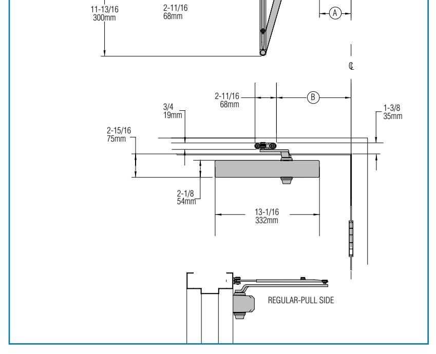
The 'A' dimension refers to the edge of the closer body to the center line of pivot or hinge. The 'B' dimension refers to the edge of the closer shoe bracket to the center line of pivot or hinge.
- Butt Hinges should not exceed 5" (127 mm) in width.
- Auxiliary Stop is recommended at hold-open point or where a door cannot swing 180°.
- Reveal should not exceed 3/4" (19 mm) for regular arm or 1/2" (13 mm) for hold-open arm.
- Top Rail less than 2-1/2" (64 mm) requires PLATE, 1450-18. With Full cover, use PLATE, 1450-18FC. Plate requires 1-1/2" (38 mm) minimum.
- Clearance of 2-3/8" (60 mm) behind door required for installation.
- Delayed Action
| Maximum Opening | Delayed Action Release |
|---|---|
| 100° | 62° |
| 130° | 66° |
| 1800 | 730 |
Options
- Delayed action cylinder.
- Hold-open arm.
- Full metal cover. (MC)
- Full plastic cover. (FC)
Special Templates

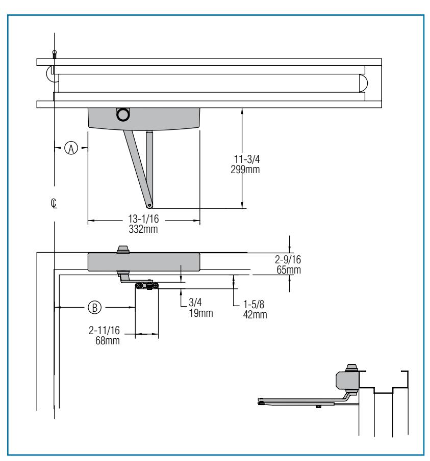
TOP JAMB (PUSH SIDE) MOUNTING
MAXIMUM OPENING
1009
- = 7" (102 mm)
- (B) = 12-3/8" (314 mm)
100° to 130°
- = 5-1/2" (140 mm)
- (B) = 10-7/8" (276 mm)
130° to 180°
- (A) = 4'' (102 mm)
- (B) = 9-3/8" (238 mm)
Hold-open points up to maximum opening with hold-open arm.
The 'A' dimension refers to the edge of the closer body to the center line of pivot or hinge. The 'B' dimension refers to the edge of the closer shoe bracket to the center line of pivot or hinge.
- Butt Hinges should not exceed 5" (127 mm) in width.
- Auxiliary Stop is recommended at hold-open point or where a door cannot swing 180°.
■ Reveal
| Arm Type | Reveal | Max. Opening |
|---|---|---|
| Regular Arm | 5" | Up to 170° |
| Regular Arm | 3-3/4" | Up to 180° |
| Long Arm | 8" | Up to 155° |
| Hold Open Arm | 2-3/4" | Up to 180° |
| Long Hold-Open Arm | 4-7/8" | Up to 140° |
- Top Rail requires 2-1/8" (54 mm) minimum. 3-3/8" (86 mm) minimum with closer on PLATE, 1450-18.
- Head Frame less than 1-3/4" (44 mm) requires PLATE, 1450-18. For flush ceiling condition with 1-3/4" (45 mm) headframe, use PLATE, 1450-18.
■ Delayed Action
| Maximum Opening | Delayed Action Release | ||
|---|---|---|---|
| 100° | 740 | ||
| 130° | 830 | ||
| 1800 | 900 | ||
Options
- Delayed action cylinder.
- Long arm, hold-open arm, long hold-open arm.
- Full metal cover. (MC)
- Full plastic cover. (FC)
Special Templates

PARALLEL ARM (PUSH SIDE) MOUNTING
Optional mounting requires PA SHOE, 1450-62PA for REGULAR or HOLD-OPEN arms. 1450 closer includes 1450-201 FIFTH HOLE SPACER to support PA SHOE.
MAXIMUM OPENING
To 120°
- A = 3-3/16" (81 mm)
- B = 8-7/8" (225 mm)
120° to 180°.
- A = 11/16" (17 mm)
- B = 6-3/8" (162 mm)
Hold-open points up to maximum opening with hold-open arm.
B 4 102mm 5-3/8 136mm 20-3/8 517mm 13-1/16 332mm A CL 4-1/8 105mm 2-1/8 54mm
The 'A' dimension refers to the edge of the closer body to the center line of pivot or hinge. The 'B' dimension refers to the edge of the closer shoe bracket to the center line of pivot or hinge.
1450 REGULAR or HOLD-OPEN MOUNT
- n Butt Hinges should not exceed 5" (127 mm) in width.
- n Auxiliary Stop is recommended at hold-open point, where a door cannot swing 180°, or where CUSH-N-STOP arm is not used.
- n Clearance for 1450-62PA shoe is 4-1/8" (105 mm) from door face.
- n Top Rail less than 5-1/4" (133 mm) measured from the soffit requires plate. Plates require 1-1/4" (32 mm) minimum.
| Cover |
Minimum Top Rail
(measured from soffit) |
Plate Required |
|---|---|---|
| Plastic | 3-1/2" (89 mm) | 1450-18 |
| 2-1/4" (57 mm) | 1450-18PA | |
| 3-1/2" (89 mm) | 1450-18FC | |
| Metal | 2-1/4" (57 mm) | 1450-18PAFC |
- n Head Frame flush or single rabbeted requires PA SHOE ADAPTER, 1450-418.
- n Stop Width minimum 1" (25 mm).
- n Blade Stop clearance, requires 1/2" (13 mm) BLADE STOP SPACER, 1450-61.
- n Auxiliary Shoe, 1450-62A allows installation of regular arm with overhead holder/stop.
- n Delayed Action
| Maximum Opening | Delayed Action Release |
|---|---|
| 120° | 65° |
| 180° | 73° |
Options
- n Delayed action cylinder.
- n Hold-open, EDA, HEDA, CUSH, HCUSH, SPRING CUSH, or SPRING HCUSH arms.
- n Full metal cover. (MC)
- n Full plastic cover. (FC)
Special Templates

1450 EDA / HEDA MOUNT
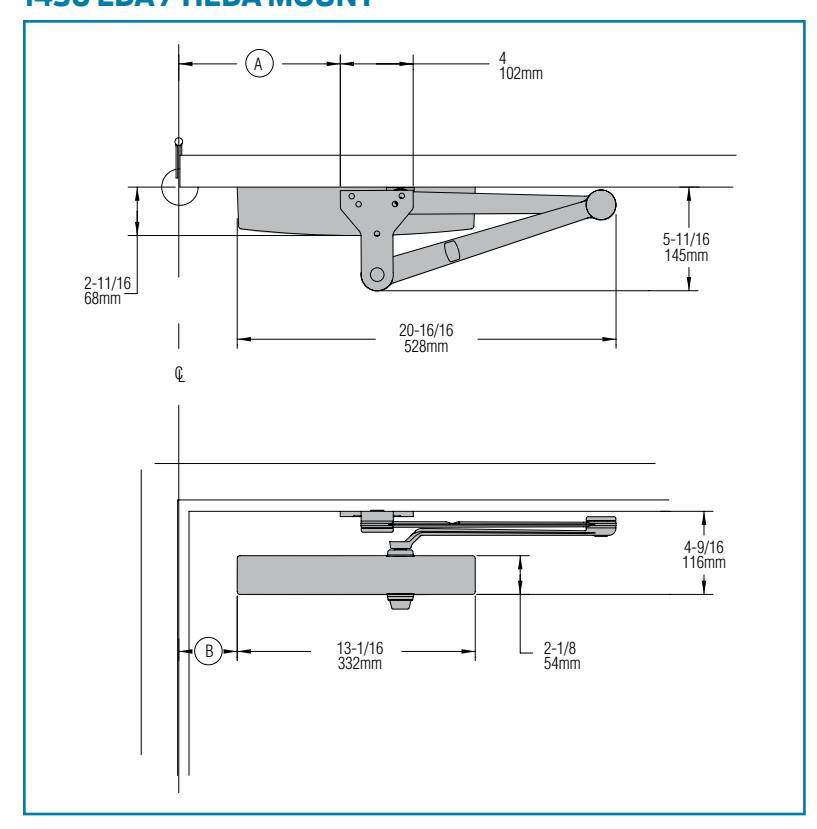
1450 CUSH / HCUSH / SCUSH / SHCUSH MOUNT
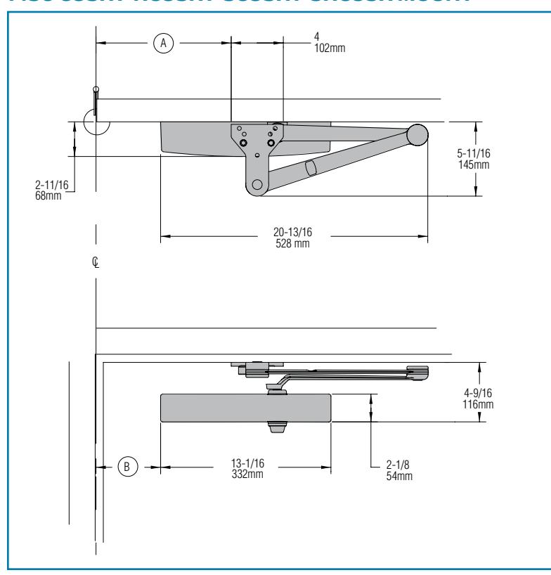
The 'A' dimension refers to the edge of the closer body to the center line of pivot or hinge. The 'B' dimension refers to the edge of the closer shoe bracket to the center line of pivot or hinge.
LCN®
1450 EDA OR CUSH-N-STOP MOUNTING
1450 closers ordered with EDA, CUSH or SPRING CUSH arms include 1450-201 FIFTH HOLE SPACER to support the shoe.
MAXIMUM OPENING
EDA template allows 110°. Hold-open point up to maximum opening. 120°.
(225 mm) = 8-7/8" (225 mm)
(81 mm)
over 120°.
= 6-3/8" (162 mm)
(17 mm)
CUSH arms can be templated for maximum opening/hold-open point at: 85°,
= 10-3/8" (279 mm)
(140 mm)
900
= 9-5/8" (244 mm)
(B) = 4-3/16" (106 mm)
959,
= 8-7/8" (225 mm)
(B) = 3-7/16'' (87 mm)
or 100°.
= 8-1/4" (210 mm)
(B) = 2-13/16" (71 mm)
105%,
= 7-5/8" (194 mm)
(B) = 2-3/16" (56 mm)
1100
= 7" (178 mm)
(B) = 1-9/16" (40 mm)
- Spring CUSH hold open points are approximately 5° less than dead stop point.
- Clearance for 1450-62EDA or CUSH shoe is 5-11/16" (144 mm) from door face.
- Head Frame flush or rabbeted requires PA FLUSH PANEL ADAPTER, 1450-419.
- EDA or CUSH ARM requires SHOE SUPPORT, 1450-30 for fifth screw anchorage where reveal is less than 3-1/16" (78 mm).
CYLINDERS
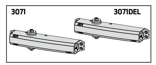
CYLINDER, 1450-3071
Standard, non-handed cast aluminum cylinder assembly.
CYLINDER, 1450-3071DEL
Cylinder used for delayed action options.
ARMS
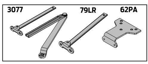
REGULAR ARM, 1450-3077
Non-handed arm mounts hinge side or top jamb. P1450 closer includes PA SHOE, 1450-62PA required for parallel arm mounting.
PA SHOE, 1450-62PA
Required for parallel arm mounting.
LONG ARM, 1450-3077L
Optional, non-handed arm includes LONG ROD AND SHOE, 1450-79LR for top jamb mount with deep reveals.
HOLD-OPEN ARM, 1450-3049
Optional, non-handed arm mounts hinge side, top jamb or parallel arm (62PA required). Hold-open adjustable at shoe.
LONG HOLD-OPEN ARM, 1450-3049L
Optional non-handed arm includes LONG HEAD AND TUBE, 1450-3048L for top jamb mount with deep reveals.
EXTRA DUTY ARM, 1450-3077EDA, 1450-3077EDA/62G
Optional, non-handed parallel arm features solid forged steel main and forearm for potentially abusive installations. Optional 1450-3077EDA/62G for blade stop clearance.
HEDA ARM, 1450-3049EDA
Optional handed arm, provides hold-open function adjustable at shoe.
CUSH-N-STOP® ARM, 1450-3077CNS
Optional, non-handed parallel arm features solid forged steel main arm and forearm with stop in soffit shoe.
HCUSH ARM, 1450-3049CNS
Optional non-handed arm, provides hold-open function with templated stop/hold-open points. Handle controls hold-open function.
SPRING CUSH ARM, 1450-3077SCNS
Optional, non-handed parallel arm for abusive applications features solid forged steel main arm and forearm with spring loaded stop in the soffit shoe.
SPRING HCUSH ARM, 1450-3049SCNS
Optional, non-handed parallel arm for abusive applications features solid forged steel main arm and forearm with spring loaded stop in the soffit shoe. Handle controls hold-open function.

PHONE 877-671-7011 FAX 800-248-1460 www.allegion.com/us 3/15 Addendum 010679
COVERS
COVER, 1450-72
Standard, non-handed, slim line plastic cover with feature strip.
FULL METAL COVER, 1450-72MC
Optional, handed metal cover provides complete enclosure.
FULL PLASTIC COVER, 1450-72FC
Optional, non-handed, full plastic cover.
INSTALLATION ACCESSORIES
PLATE, 1450-18/1450-18FC
Required for hinge side mount where top rail is less than 2-1/2" (64 mm). Required for top jamb mounting where head frame is less than 1-3/4" (44 mm) or flush ceiling condition exists. Plate requires minimum 1-1/2" (38 mm) minimum top rail or 1-1/4" (32 mm) head frame. With full cover, use PLATE, 1450-18FC.
PLATE, 1450-18PA/1450-18PAFC
Required for parallel arm mounting where top rail is less than 4-3/8" (111 mm), measured from the stop. Plate requires 1-3/4" (44 mm) minimum top rail. With full cover, use PLATE, 1450-18PAFC.
CUSH SHOE SUPPORT, 1450-30
Provide anchorage for fifth screw used with CUSH arm where reveal is less than 3-1/16" (78 mm).
BLADE STOP SPACER, 1450-61
Lowers parallel arm shoe to clear 1/2" (13 mm) blade stop.
AUXILIARY SHOE, 1450-62A
Requires a top rail of 7" (178 mm). Optional shoe replaces -62PA for parallel arm mounting of regular arm with overhead holder/stop.
FLUSH PANEL ADAPTER, 1450-419
Provides horizontal mounting surface for PA, EDA, or CUSH shoe on single rabbeted or flush frame.
72 72MC 72FC
Right hand shown
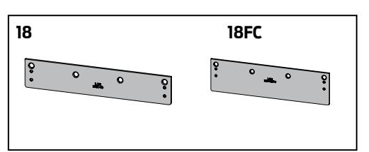
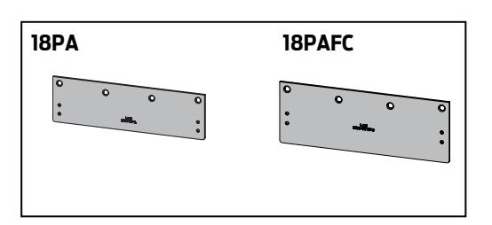
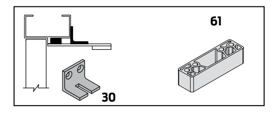
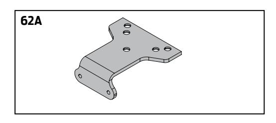
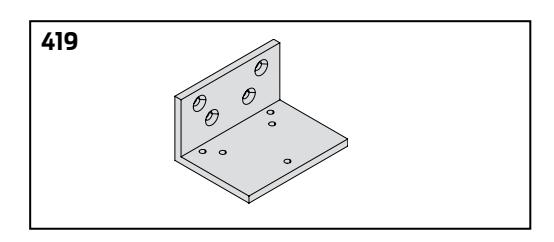
TABLE OF SIZES
Select closer based on width of door.
The spring power of a 1450 cylinder is field adjustable from size 1 through size 6 and is shipped adjusted to size 3.
EXTERIOR (and VESTIBULE) DOOR WIDTH
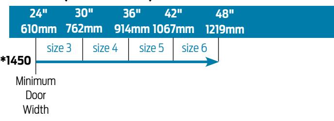
INTERIOR DOOR WIDTH
|
24"
610mm |
34"
610mm |
38"
48" 965mm 1219mm |
54"
1372mm |
60"
1524mm |
|
|---|---|---|---|---|---|
| *1450 | size 2 | size 3 | size 4 | size 5 | size 6 |
|
Minimum
Door Width |
* Adjustable Size 1 thru 6 |
Indicates recommended range of door width for closer size.
REDUCED OPENING FORCE 1450 CLOSERS
CAUTION ! Any manual door closer, including those certified by BHMA to conform to ANSI Standard A156.4, that is selected, installed and adjusted based on ADA or other reduced opening force requirements may not provide sufficient power to reliably close and latch a door.
Refer to POWER OPERATORS section for information on systems that meet reduced opening force requirements without affecting closing power.
| DOOR WIDTH | 36" | 42" | 48" | |
|---|---|---|---|---|
| 8.5* lbs. | 1450 | 1450 | 1450 | |
| 5.0* lbs. | 1450 | 1450 | 1450 |
* Maximum opening force.
HOW TO ORDER 1450 SERIES CLOSERS
1. SELECT FINISH
Standard Powder Coat __________ Aluminum, Dark Bronze, Statuary, Light Bronze, Black, Brass.
Closer will be shipped with:
- STANDARD CYLINDER
- STANDARD COVER
- TRI PACK ARM
- UNIVERSAL SCREW PACK unless options listed below are selected.
CLOSER OPTIONS
CYLINDER
Delayed Action (DEL)
COVER
Full Metal cover (MC) Full Plastic cover (FC)
FINISH
Custom (RAL) ___________ (Metal cover required)
Plated Finish, US ___________ (Metal cover required)
SRI primer
ARM
Regular w/62PA (Rw/PA)
Long (LONG)
Regular w/62A (Rw/62A)
Hold-Open w/62PA (Hw/PA)
Long Hold-Open (HLONG)
EDA (optional -62G)
HEDA (specify right or left hand)
Cush-N-Stop (CUSH)
HCush (HCUSH)
Spring Cush (SCUSH)
Spring HCush (SHCUSH)
OPTIONAL SCREW PACKS
TORX Machine Screw (TORX)
TB* & TORX Machine Screw (TBTORX)
* Specify door thickness if other than 1-3/4".
SPECIAL TEMPLATE
ST- _________
MEETS BUY AMERICAN ACT
BAA
INSTALLATION ACCESSORIES
Plate, 1450-18
Plate, 1450-18FC
Plate, 1450-18PA
Plate, 1450-18PAFC
CUSH Shoe Support, 1450-30
Blade Stop Spacer, 1450-61
Auxiliary Shoe, 1450-62A
PA Flush Panel Adapter, 1450-419

4050 SERIES SURFACE MOUNTED CLOSER
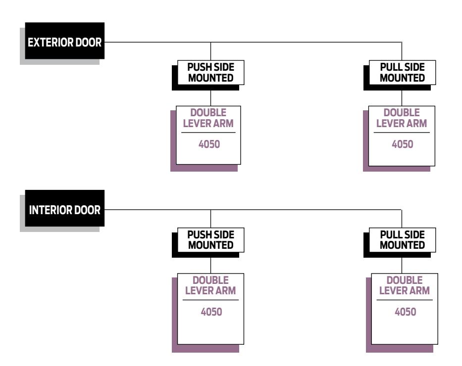
PRODUCT SELECTION GUIDE
Surface mounted 4050 Series LCN closers feature a modern design engineered for each application, easy installation, and superior performance. This guide is based on the desired mounting of the closer.
PRODUCT COMPARISON
This chart shows a basic comparison of 4050 Series closers.

- AVAILABLENOT AVAILABLE
- Closer available with less than 5.0 lbs. opening force on 36" door.
- * Maximum opening/hold-open point with standard template.
- ** Advanced Variable Backcheck.

4050 SERIES SURFACE MOUNTED CLOSER
APPLICATIONS
- n For aluminum, hollow metal, or wood swinging doors and frames.
- n Can be used with hinge or pivot mounted door.
- n Adapter plates and other installation accessories available for unusual conditions.
FEATURES COMMON TO 4000 SERIES
- n The 4050 closer mounts three ways: hinge side, top jamb, or parallel arm. 4050 closer with regular or hold-open arm mounts hinge side or top jamb. 4050 parallel arm closers include 62PA SHOE required to parallel arm mount either regular or hold-open arm.
- n Closers to meet ADA reduced opening force requirements.
- n Adjustable hydraulic backcheck cushions opening swing.
- n Separate regulation of general closing speed and latching speed.
- n Joints in regular arm and shoe adapt to uneven trim.
- n Reversible shoe to boost latching power on double lever arms.
- n Available in a wide range of standard or optional custom powder coat finishes to blend with door and frame.
- n Plated finishes available to accent door and frame.
- n Not designed for exterior mounting or exposed to elements.
DESIGN ASSISTANCE
LCN has been providing reliable solutions to unique door control problems for over 85 years. Design and specification assistance are only a phone call away.
Contact LCN for assistance or technical information at 877-671-7011 or FAX 800-248-1460 (Order Entry) , Fax 815-879-1495 for Product Support.
WARRANTY
25 year limited warranty on cast aluminum. See General Information Section for complete warranty details.
SPECIFICATIONS
Refer to "SPECIFICATIONS" section for suggested architectural specifications.
MATERIALS
- n High strength cast aluminum cylinder.
- n Forged steel main arms.
- n Double heat treated pinion.
- n All weather fluid for cast aluminum performs to -30 degrees.
- n High efficiency, full complement , low friction bearings.
- n Tamper resistant regulating screws.
- n Full rack and pinion hydraulic action.
FINISHES
- n Available in six standard or optional custom powder coat finishes to blend with door and frame.
- n LCN's powder coat finishes surpass 100 hours of salt spray which is over four times the ANSI standard for corrosion resistance.
- n For installations where a higher level of corrosive resistance is required, LCN offers an optional special rust inhibiting (SRI) pretreatment. Closers that combine the exclusive LCN powder coat finish and the SRI pre-treatment exceed the ANSI standard for corrosion resistance even further.
- n Plated finishes are available as an option to accent door and frame. (SRI not available with plated finishes).
LISTINGS & APPROVALS
UL listed for self-closing doors without hold-open under "SWINGING DOOR CLOSERS"(GVEV).
Tested and certified under ANSI Standard A156.4 Grade One. Consult factory for details.
Consult factory for other listings such as; cUL, California State Fire Marshal, Bureau of Standards and Appeals.
POSITIVE PRESSURE

LCN closers have been certified for three hours by UL to be in compliance with UBC 7.2 (1997) and UL 10C. Contact LCN for specific details on door closer fire ratings.
FASTENERS
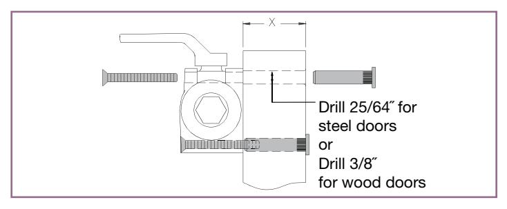
4050 Series closers are shipped with: Self Reaming and Tapping (SRT) and Machine Screws. Thru Bolts, Wood Screws and TORX Security Screws are optional.
Notes:
- 1. For Thru Bolts, specify door thickness if other than 1-3/4" (44mm), represented in diagram as dimension "X".
- 2. Phillips head, metric machine screws are available, please specify.
- 3. LCN recommends the use of wood screws, available in optional WMS screw packs, for wood door applications.
MAINTENANCE
Closers mounted according to LCN installation instructions require no periodic maintenance.

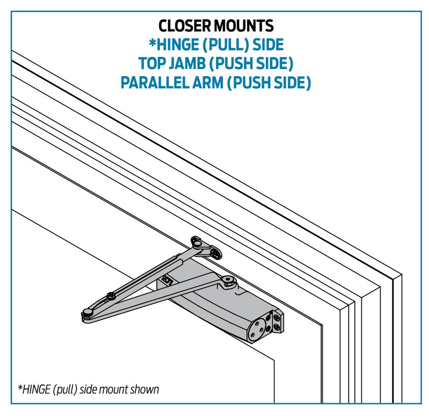
CLOSER MOUNTS *HINGE (PULL) SIDE TOP JAMB (PUSH SIDE) PARALLEL ARM (PUSH SIDE) *HINGE (pull) side mount shown
- Standard 4050 Series closer shipped with tri-pack arms: regular, parallel, and top jamb, standard full plastic cover, and self reaming and tapping screws.
- Non-sized cylinder is adjustable for interior doors to 5'0" and exterior doors to 4'0".
- Closer mounts hinge side, top jamb, and parallel arm on either right or left swinging doors.
- Closer meets ADA requirements.
- Standard or optional custom powder coat finish.
- Optional plated finish on cover, arm, and fasteners.
- UL and cUL listed for self-closing doors without hold-open.
- Tested and certified under ANSI Standard A156.4, grade one.
4050 SERIES
The 4050 Series cast aluminum closer is engineered for durability and built tough to excel in the harsh environments of high frequency, high abusive traffic areas. Ideal for commercial building applications and competitive specification situations that demand a combination of quality, reliability and value. The cast aluminum door closer offers premium features like powder coating, full complement bearing, All Weather Fluid and a 25 year warranty.
- Cast Aluminum
- Forged Steel Arm
- Double Heat Treated Steel Pinion
- All Weather Fluid
- Non-Handed
- Peel-n-Stick Templates for Fast and Accurate Installation
- UL & cUL Listed
- 3/4" Journal Diameter Pinion
- Full Complement Bearing
- Adjustable spring size 1-6
- 25 Year Warranty

AVAILABLENOT AVAILABLE
- & Closer available with less than 5.0 lbs. opening force on 36" door.
- * Maximum opening/hold-open point with standard template.
- ** Advanced Variable Backcheck.

HINGE (PULL) SIDE MOUNTING
MAXIMUM OPENING
Templating allows up to 180°.
Hold-open points up to maximum opening with hold-open arm.
To 100°
- (A) = 6-15/16" (176mm)
- (B) = 12-5/8" (321 mm)
100° to 120°,
- = 5-15/16" (151mm)
- (B) = 11-5/8" (295 mm)
120° to 150°.
- = 3-15/16" (100 mm)
- (B) = 9-5/8" 244 mm)
150° to 180°.
- = 3-7/16" (87mm)
- (B) = 9-1/8" (232 mm)
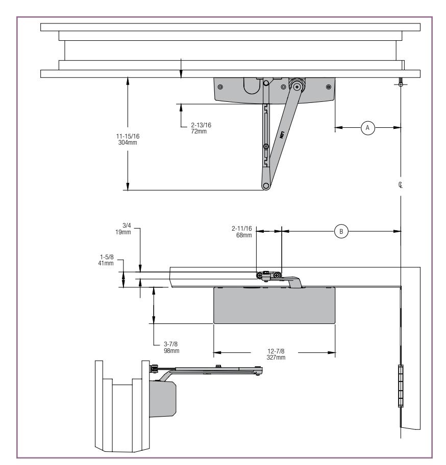
The 'A' dimension refers to the edge of the closer body to the center line of pivot or hinge. The 'B' dimension refers to the edge of the closer shoe bracket to the center line of pivot or hinge.
- Butt Hinges should not exceed 5" (127 mm) in width.
- Auxiliary Stop is recommended at hold-open point or where a door cannot swing beyond templated maximum opening.
- Reveal should not exceed 3/4" (19 mm) for regular arm or hold-open arm.
- Top Rail less than 3-7/8" (98mm) requires PLATE, 4050-18. Plate requires 1-3/4" (44mm) minimum.
- Clearance of 2-13/16" (72mm) behind door required for 90° installation.
- *Delayed Action Delays closing from 180°-70°. Delay time adjustable up to approximately 1 minute.
Options
- 4050 Delayed action cylinder*.
- Hold-open arm.
- Metal cover.
Special Templates

TOP JAMB (PUSH SIDE) MOUNTING
MAXIMUM OPENING
Templating allows up to 180°.
Hold-open points up to maximum opening with hold-open arm.
To 100°
- A = 6-7/8" (175 mm)
- B = 12-11/16" (322 mm)
100° to 120°,
- A = 5-7/8" (149 mm)
- B = 11-11/16" (297 mm)
120° to 150°,
- A = 3-7/8" (98 mm)
- B = 9-11/16" (246 mm)
150° to 180°,
- A = 3-3/8" (86 mm)
- B = 9-3/16" (233 mm)
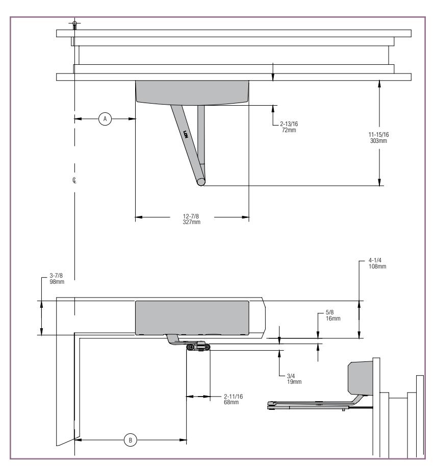
The 'A' dimension refers to the edge of the closer body to the center line of pivot or hinge. The 'B' dimension refers to the edge of the closer shoe bracket to the center line of pivot or hinge.
- n Butt Hinges should not exceed 5" (127 mm) in width.
- n Auxiliary Stop is recommended at hold-open point or where a door cannot swing beyond templated maximum opening.
n Reveal
| Arm Type | Reveal | Max. Opening |
|---|---|---|
| Regular | 4" | Up to 180° |
| Long | 9" | Up to 150° |
| Hold-Open | 4" | Up to 170° |
| Long Hold-Open | 8-3/4" | Up to 155° |
- n Top Rail requires 2" (51mm) minimum. Contact LCN Product Support for requirements when using plates.
- n Head Frame less than 3-7/8" (98 mm) requires plate. Contact LCN Support for requirements when using plates.
- n *Delayed Action Delay closing from 180° to 70° . Delay time adjustable up to approximately 1 minute.
Options
- n 4050 Delayed action cylinder*.
- n Hold-open arm.
- n Metal cover.

PARALLEL ARM (PUSH SIDE) MOUNTING
Optional mounting requires PA SHOE, 4050-62PA for regular or HOLD-OPEN arms.
MAXIMUM OPENING
To 100°
A = 8-1/16" (205 mm)
B = 8-5/8" (219 mm)
100° to 130°,
A = 6-9/16" (167 mm)
B = 7-1/8" (181 mm)
130° to 150°,
A = 5-9/16" (141 mm)
B = 6-1/8" (156 mm)
150° to 180°,
A = 4-9/16" (116 mm)
B = 5-1/8" (130 mm)
Hold-open points up to maximum opening with hold-open arm.
15-1/2 394mm 5-3/4 146mm 12-7/8 327mm 3-7/8 98mm 2-13/16 72mm 102mm 4-1/8 105mm CL
The 'A' dimension refers to the edge of the closer body to the center line of pivot or hinge. The 'B' dimension refers to the edge of the closer shoe bracket to the center line of pivot or hinge.
- n Butt Hinges should not exceed 5" (127 mm) in width.
- n Auxiliary Stop is recommended at hold-open point, where the door cannot swing beyond templated maximum opening, or where CUSH-N-STOP arm is not used.
- n Clearance for 4050-62PA shoe is 4-1/8" (105 mm) from door face.
- n Top Rail less than 5-3/4" (146mm) measured from the stop requires PLATE, 4050-18PA. Plate requires 2-1/4" (57 mm) minimum from the stop.
- n Head Frame flush or rabetted requires PA SHOE ADAPTER, 4050-419.
- n Stop Width minimum 1-3/16" (30 mm).
- n Blade Stop clearance requires 1/2" (13mm) BLADE STOP SPACER, 4050-61.
- n *Delayed Action Delays closing from 180° to 70°. Delay time adjustable up to approximately 1 minute.
- n Auxiliary Shoe 4050-62A allows installation of regular arm with overhead holder/stop

- n 4050 Delayed action cylinder*.
- n Hold-open, EDA, HEDA, CUSH, HCUSH, SPRING CUSH or SPRING HCUSH arm.
- n Metal cover.
Special Templates

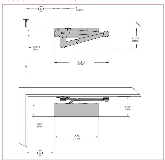
4050 SERIES EDA MOUNT
4050 SERIES CUSH MOUNT
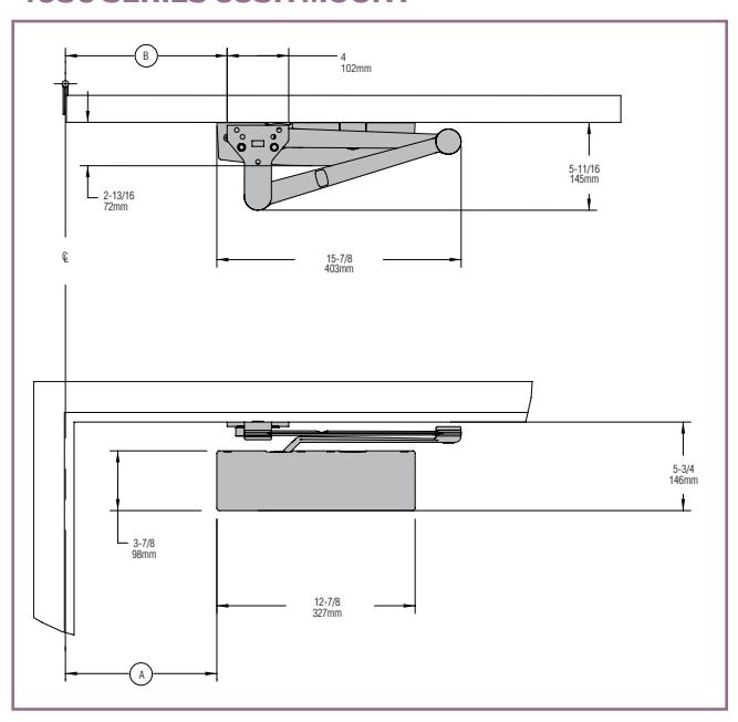
The 'A' dimension refers to the edge of the closer body to the center line of pivot or hinge. The 'B' dimension refers to the edge of the closer shoe bracket to the center line of pivot or hinge.
- n Clearance for 4050-62EDA is 5-11/16" (145mm) from door face. 5-11/16" (145mm) for CUSH.
- n Head Frame flush or rabetted requires FLUSH PANEL ADAPTER, 4050-419.
- n CUSH ARM requires SHOE SUPPORT, 4050-30 for fifth screw anchorage for narrow frames.
- n *Delayed Action Delays closing from 180° to approximately 70°. Delay time adjustable up to approximately 1 minute.
Mounting details are the same as 4050 Series REGULAR or HOLD-OPEN except as listed below. 4050 Series closers ordered with EDA or CUSH arms include 4050-201 FIFTH HOLE SPACER to support the shoe.
MAXIMUM OPENING
EDA arm can be templated for points at: to 100°,
A = 8-1/16" (205 mm)
B = 8-5/8" (219 mm)
100° to 130°,
A = 6-9/16" (167 mm)
B = 7-1/8" (181 mm)
130° to 150°,
A = 5-9/16" (141 mm)
B = 6-1/8" (156 mm)
150° to 180°,
A = 4-9/16" (116 mm)
B = 5-1/8" (130 mm)
Hold-open points up to maximum opening with HEDA arm.
CUSH arms can be templated for opening/hold-open point at:
85°,
A = 9-13/16" (250 mm)
B = 10-1/2" (267 mm)
90°,
A = 8-15/16" (227 mm)
B = 9-5/8" (244 mm)
95°,
A = 8-5/16"(212 mm)
B = 9" (229 mm)
100°,
A = 7-11/16"(196 mm)
B = 8-3/8" (213 mm)
105°,
A = 7-1/16" (180 mm)
B = 7-3/4"(197 mm)
110°,
A = 6-9/16"(167 mm)
B = 7-1/4" (184 mm)
Spring Cush dead stop points are approximately 5˚ more than templated stop point. Hold open at templated stop points.
PHONE 877-671-7011 FAX 800-248-1460 www.allegion.com/us 09/15 Addendum 010680

CYLINDERS
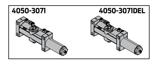
CYLINDER, 4050-3071
Heavy duty, non-handed cast aluminum cylinder assembly.
CYLINDER, 4050-3071 DEL
Cylinder used for delayed action options.

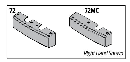
COVER, 4050-72
Standard, non-handed plastic cover.
METAL COVER, 4050-72MC
Optional, handed cover. Required for plated finishes and custom powder coat finishes.
ARMS
REGULAR ARM, 4050-3077
Non-handed arm mounts pull side or top jamb with shallow reveal. Includes PA SHOE, 4050-62PA required for parallel arm mounting.
PA SHOE, 4050-62PA
Required for parallel arm mounting.
LONG ARM, 4050-3077L
Optional non-handed arm includes LONG ROD AND SHOE, 4050-79LR for top jamb mount.
HOLD-OPEN ARM, 4050-3049
Optional, non-handed arm mounts pull side or top jamb with shallow reveal, hold-open adjustable shoe. 4050 closer includes 4050-62PA shoe required for parallel arm mounting.
LONG HOLD-OPEN ARM, 4050-3049L
Optional non-handed arm includes LONG HEAD AND TUBE, 4050-3048L for top jamb mount.
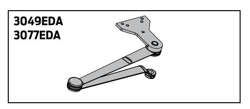
EXTRA DUTY ARM, 4050-3077EDA
Non-handed parallel arm features forged, solid steel main and forearm for potentially abusive installations.
HOLD-OPEN EXTRA DUTY ARM, 4050-3049EDA
Handed parallel arm features forged, solid steel main and forearm for potentially abusive installations. Hold-open function is adjusted at the shoe.
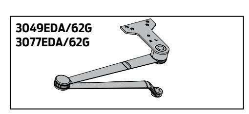
EXTRA DUTY ARM WITH 62G, 4050-3077EDA/62G
Non-handed parallel arm features forged, solid steel main and forearm for potentially abusive installations. 62G shoe provides additional blade stop clearance.
HOLD-OPEN EXTRA DUTY ARM WITH 62G, 4050-3049EDA/62G
Handed parallel arm features forged, solid steel main and forearm for potentially abusive installations. 62G shoe provides additional blade stop clearance. Hold-open function is adjusted at the shoe.

ARMS cont.
CUSH-N-STOP® ARM, 4050-3077CNS
Optional, non-handed parallel arm features solid forged steel main arm and forearm with stop in soffit shoe.
HCUSH ARM, 4050-3049CNS
Provides hold-open function with templated stop/hold-open points. Handle controls hold-open function.
SPRING CUSH ARM, 4050-3077SCNS
Optional, non-handed parallel arm for abusive applications features solid forged steel main arm and forearm with spring loaded stop in the soffit shoe.
SPRING HCUSH ARM, 4050-3049SCNS
Optional, non-handed parallel arm for abusive applications features solid forged steel main arm and forearm with spring loaded stop in the soffit shoe. Handle controls hold-open function.
INSTALLATION ACCESSORIES
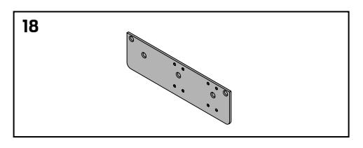
PLATE, 4050-18
Required for hinge side mount where top rail is less than 3-7/8" (98 mm). Plate requires minimum 1-3/4" (44 mm) top rail.
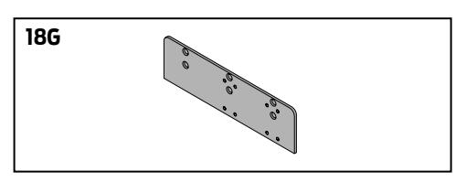
PLATE, 4050-18G
Locates top jamb mounted closer flush with top of head frame face in flush ceiling condition. Contact LCN Product Support for minimum head frame requirement.
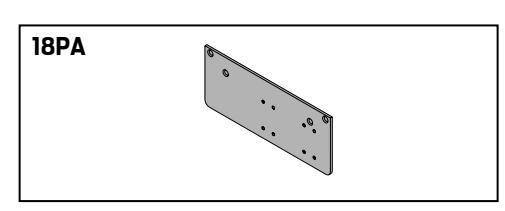
PLATE, 4050-18PA
Required for parallel arm mounting where top rail is less than 5-3/4" (146 mm), measured from the stop. Plate requires 2-1/4" (57 mm) minimum top rail.
3077CNS

INSTALLATION ACCESSORIES cont.
CUSH SHOE SUPPORT, 4050-30
Provides anchorage for fifth screw used with CUSH arms, where reveal is less than 3-1/16" (78 mm).
BLADE STOP SPACER, 4050-61
Required to lower parallel arm shoe to clear 1/2" (13 mm) blade stop.
FLUSH PANEL ADAPTER, 4050-419
Provides horizontal mounting surface for parallel arm shoe on single rabetted or flush frame.
AUXILIARY SHOE, 4050-62A
Requires a top rail of 7-13/16" (198 mm). Optional shoe replaces -62PA for parallel arm mounting of regular arm with overhead holder/stop.
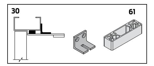
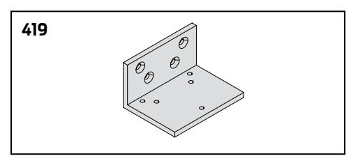
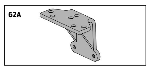

TABLE OF SIZES
4050 cylinders are adjustable from size 1 through size 6 and is shipped set to size 3.
Closing power of 4050 Series closers may be adjusted 50%.
EXTERIOR (and VESTIBULE) DOOR WIDTH
| 24" | 30" | 36" | 42" | 48" | ||
|---|---|---|---|---|---|---|
| 610mm | 762mm | 914mm | 1067mm | 1219mm | ||
| *4050 | size 3 | size 4 | size 5 | size 6 | ||
|
Minimum
Door Width |
INTERIORDOOR WIDTH
|
24"
610mm |
34"
864mm |
38"
965mm |
48"
1219mm |
54"
1372mm |
60"
1524mm |
|||
|---|---|---|---|---|---|---|---|---|
| *4050 | size 2 | size 3 | size 4 | size 5 | size 6 | |||
|
Minimum
Door Width |
Indicates recommended range of door width for closer size.
REDUCEDOPENING FORCE 4050 SERIES CLOSERS
CAUTION ! Any manual door closer, including those certified by BHMA to conform to ANSI Standard A156.4, that is selected, installed and adjusted based on ADA or other reduced opening force requirements may not provide sufficient power to reliably close and latch a door.
Refer to POWER OPERATORS section for information on systems that meet reduced opening force requirements without effecting closing power.
|
DOOR
WIDTH |
36" | 42" | 48" |
|---|---|---|---|
| 8.5* lbs. | 4050 | 4050 | 4050 |
| 5.0* lbs. | 4050 | 4050 | 4050 |
* Maximum opening force.
HOW-TO-ORDER 4050 SERIES CLOSERS
1. SELECT FINISH
Standard Powder Coat __________ Aluminum, Dark Bronze, Statuary, Light Bronze, Black, Brass.
Closer will be shipped with:
- STANDARD CYLINDER
- STANDARD PLASTIC COVER
- TRI PACK ARM (Rw/PA)
- SELF-REAMING and TAPPING SCREWS, unless options listed below are selected.
CLOSEROPTIONS
CYLINDER
Delayed Action (4050 DEL)
COVER
Metal (specify right or left hand) (MC)
FINISH
- Custom Powder Coat (RAL) ___________
- (handed metal cover required)
-
Plated Finish, US ______________
- (handed metal cover required)
- SRI primer (use with powder coat finishes only)
ARM
- Regular w/62A (R/62A)
- Long (LONG)
- Hold-Open (H)
- Hold-Open w/62PA (Hw/PA)
- Long Hold-Open (HLONG)
- Extra Duty Arm (EDA)
- Extra Duty Arm with 62G (EDA/62G)
- Hold Open Extra Duty Arm (HEDA) (Handed)
- Hold Open Extra Duty Arm with 62(HEDA/62G)(Handed)
- Cush-N-Stop (CUSH)
- HCush-N-Stop (HCUSH)
- Spring Cush (SCUSH)
- Spring HCush (SHCUSH)
OPTIONAL SCREW PACKS
- TB* w/Self-Reaming and Tapping (TBSRT)
- Wood & Machine Screw (WMS)
- TB*, Wood & Machine Screw (TBWMS)
- TORX Machine Screw (TORX)
- TB* & TORX Machine Screw (TBTRX)
- * Specify door thickness if other than 1-3/4".
INSTALLATION ACCESSORIES
- Plate, 4050-18
- Plate, 4050-18G
- Plate, 4050-18PA
- CUSH Shoe Support, 4050-30
- Blade Stop Spacer, 4050-61
- Auxiliary Shoe, 4050-62A
- Flush Panel Adapter, 4050-419
SPECIAL TEMPLATE
| ST |
|---|

* Adjustable Size 1 thru 6.
Notes