Jackson 1085-1085P CVR Installation Instruction
Open the original PDF document
View PDFINSTALLATION INSTRUCTIONS
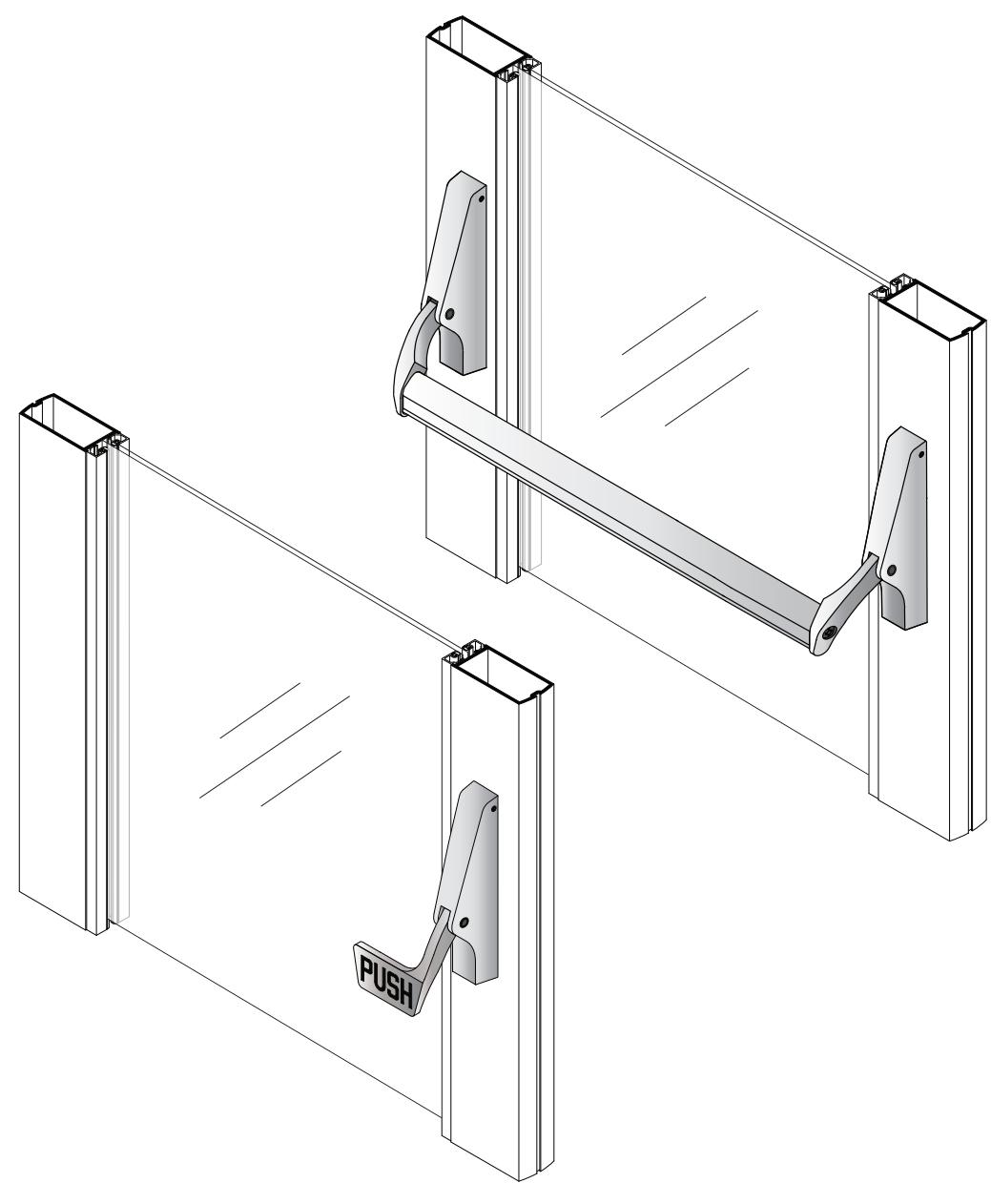
CRL JACKSON 1085-1085P CONCEALED VERTICAL ROD PANIC EXIT DEVICE

Phone: (800) 421-6144 • Fax: (866) 921-0531 crlaurence.com • usalum.com • crl-arch.com
CRL JACKSON 1085-1085P CONCEALED VERTICAL ROD PANIC EXIT DEVICE
ORDER OF ASSEMBLY AND INSTALLATION
|
Tools Required
02 |
|
|---|---|
|
Parts Identification
03 - 04 |
|
|
Door Preparation
05 - 08 |
|
|
Door
Removal 05 |
|
| 1085 Panic Bar with Lock Cylinder and Mounting Pad (Template Selection) | 06 |
| 1085 Panic Bar and Lock Cylinder with Exterior Trim (Template Selection) | 07 |
| 1085-P Paddle Installation Only (Template Selection) | 08 |
| Door Hardware Installation | 09 - 16 |
|
Remove Dogging Pawl (Optional)
09 |
|
|
Insert Rod and Case
10 |
|
| Install Optional Mortise Cylinder | 11 |
|
Install Body and Arm Assemblies
12 |
|
| Cut and Install Panic Bar | 13 |
|
Install 1085P Paddle Version
14 |
|
| Install Optional Handle Trim | 15 |
| Adjust Rod Length/Replace Door | 16 |
|
Door Installation
17 |
|
| Frame Preparation | 18 |
|
Guide Rod Bolt Final Adjustment
19 |
|
| Dogging Pin Options | 20 |
|
Packaged Parts Available
21 - 22 |
TOOLS REQUIRED
Drill bits: 5/8", 11/64", 13/64"
Tap: 1/4"- 20 Tape measure Saw horses Cordless drill
Phillips #2 screwdriver
Slot tip screwdriver Framing square/straight edge
Masking tape Center punch Flat File Round File
Jigsaw with metal cutting blade
Allen wrenches Torx T-10 Driver
PARTS IDENTIFICATION
| FASTENERS AND PARTS LIST | |||||
|---|---|---|---|---|---|
|
CALL
OUT |
QTY. | FASTENER |
FASTENER
DESCRIPTION |
PART |
USED WITH
PART NUMBER |
| A | 2 |
1/4"- 20 x 1/4"
Shoulder Stud Bolts |
30982 Right Side Body and
Arm 30983 Left Side Body and Arm Assembly |
||
| A | 2 |
1/4"- 20 x 1/4"
Shoulder Stud Bolts |
PIGH |
30984 Right Body and Arm
30985 Left Body and Arm Paddle Assembly |
|
| B | 3 |
#10 x 1/2" FH Self
Tapping Screw |
30934 Top Bolt Guide
30320 Bottom Bolt Guide Assembly |
||
| © | 3 |
1/4"- 20 x 1/4" Set
Screw for Active Pad |
30982 Right Side Body and
Arm 30983 Left Side Body and Arm Assembly |
||
| D | 1 |
1/4"- 20 x 1"
Oval Head Screw |
30982 Right Body and Arm
30983 Left Body and Arm 30733 Package Panic Bar Assembly |
||
| E | 4 | #8 x 3/8" FH Screw |
301084 Top and Bottom
Strike Package |
||
| F | 2 | ADDITION | #8 x 3/4" FH Screw |
30824
Trip Bracket Package |
|
| G | 1 |
1/4"- 20 x 1"
Set Screw |
30824
Trip Bracket Package |
||
| H | 2 |
#8 x 2" FH
Machine Screw |
30821J
No. 86 Mortise Cylinder Mounting Pad |
||
| 1 | 2 |
#10 x 2-1/8" FH
Machine Screw |
8500LV01 and 8500LV02
Exterior Trim with Lever Assembly |
||
PARTS IDENTIFICATION
| PARTS LIST | ||||
|---|---|---|---|---|
|
CALL
OUT |
QTY. | PART | PART NO. | DESCRIPTION |
| J | 1 | 301409 |
Actuator Link included
in 1085 and 1085P Body Hardware Package Cat. No. 301409 |
|
| K | 1 |
301347
301348 |
Optional 12" and 24"
Top Rod Extender |
|
| L | 1 | 30915J | Rod Case Assembly | |
| M | 1 | DL2170 |
Optional 1" Mortise
Key Cylinder |
|
| N | 1 | 301115 |
Slotted Dogging
Pin Assembly |
|
| O | 1 | 301117 |
Optional Thumbturn
Dogging Pin Assembly |
|
| P | 1 | 30934/30320 |
Hex tool included in 30934 Top Bolt Guide
and 30320 Bottom Bolt Guide |
|
| Q | 1 | 301552 | Rod Silencer | |
DOOR PREPARATION
REMOVE DOOR
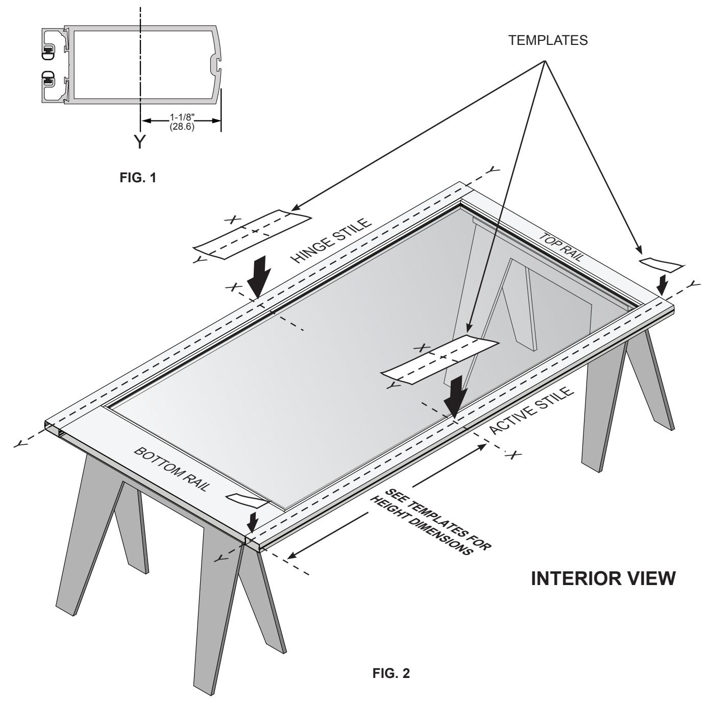
- 1. Place door horizontally on stands with the interior side up.
- 2. Mark stile Y-lines, 1-1/8" (28.6) from outside edge for all stile widths (Fig. 1).
- 3. Mark stile X-lines per template instructions (Fig. 2).
- 4. Attach corresponding templates (Fig. 2).
1085 PANIC BAR WITH LOCK CYLINDER AND MOUNTING PAD DOOR PREPARATION – TEMPLATE SELECTION
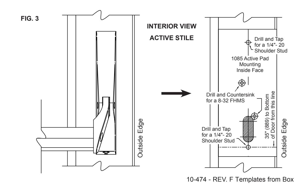
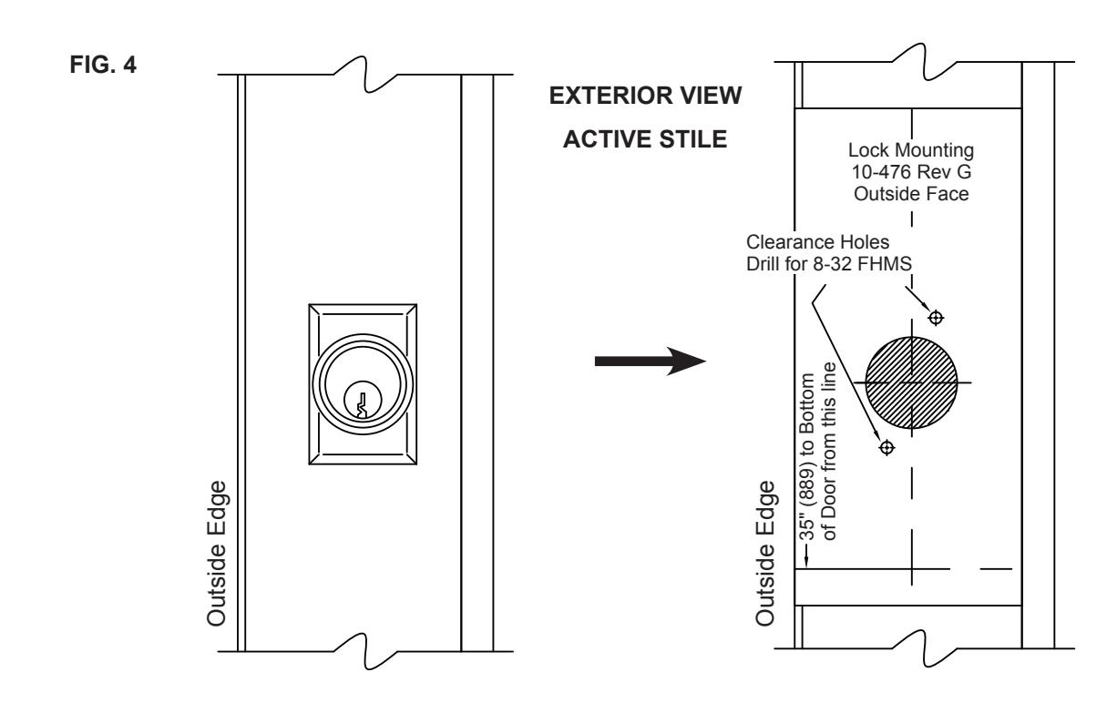
10-476 - REV. G Templates from Box
NOT TO SCALE
DOOR PREPARATION - TEMPLATE SELECTION
1085 PANIC BAR AND LOCK CYLINDER WITH EXTERIOR TRIM
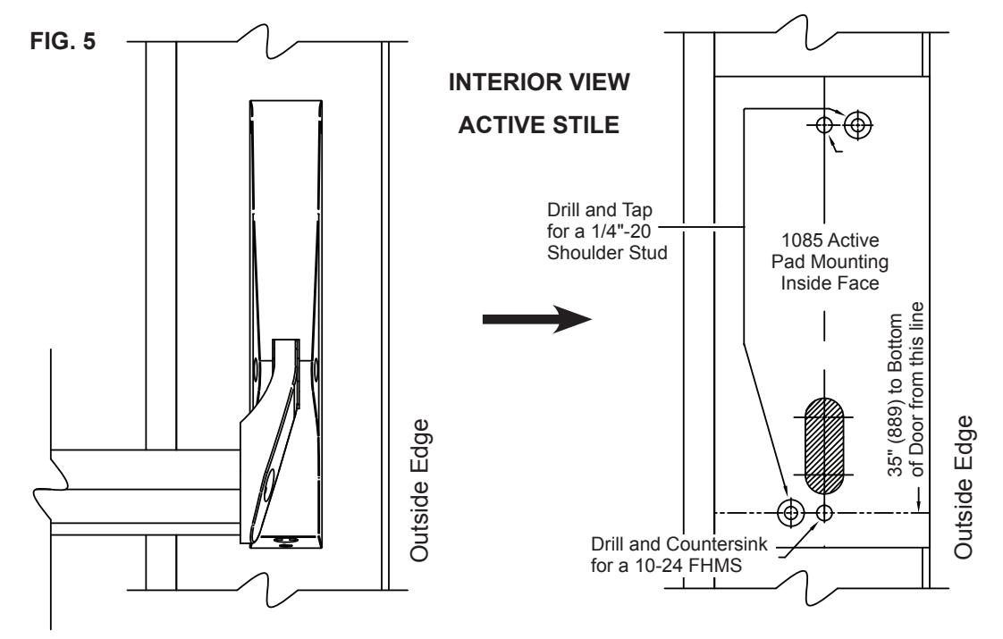
10-474 - REV. F Templates from Box

10-987 - REV. C Templates from Box
NOT TO SCALE
DOOR PREPARATION – TEMPLATE SELECTION
1085P PADDLE INSTALLATION ONLY
FIG. 7
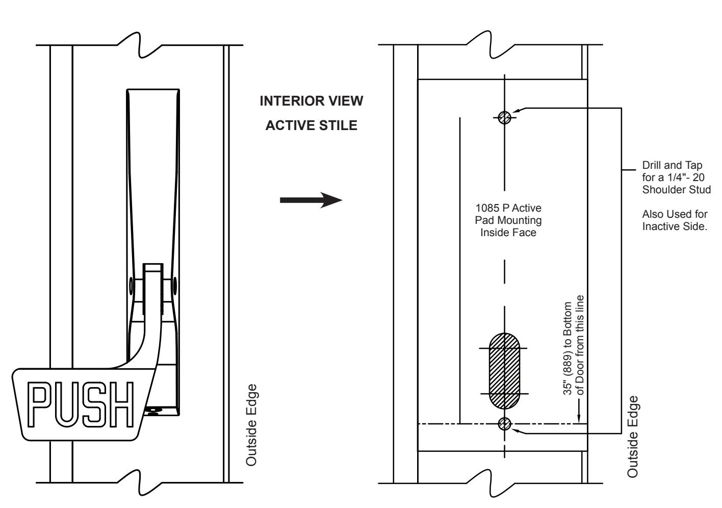
10-474 - REV. F Templates from Box
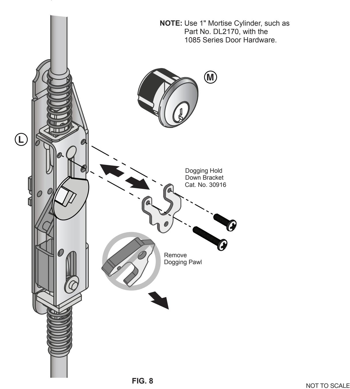
REMOVE DOGGING PAWL ONLY IF USING OUTSIDE CYLINDER LOCK DOOR HARDWARE INSTALLATION – OPTIONAL DOGGING STEP
INSTALLATION:
- 1. Remove the two screws and Dogging Hold Down Bracket (included in Cat. No. 30916).
- 2. Remove Dogging Pawl (included in Cat. No. 30916).
- 3. Re-attach the Dogging Hold Down Bracket and screws. NOTE: Left screw is longer than right screw.
- 4. Refer to page 11 for Mortise Cylinder installation.
INSERT ROD AND CASE (ALL MODELS)
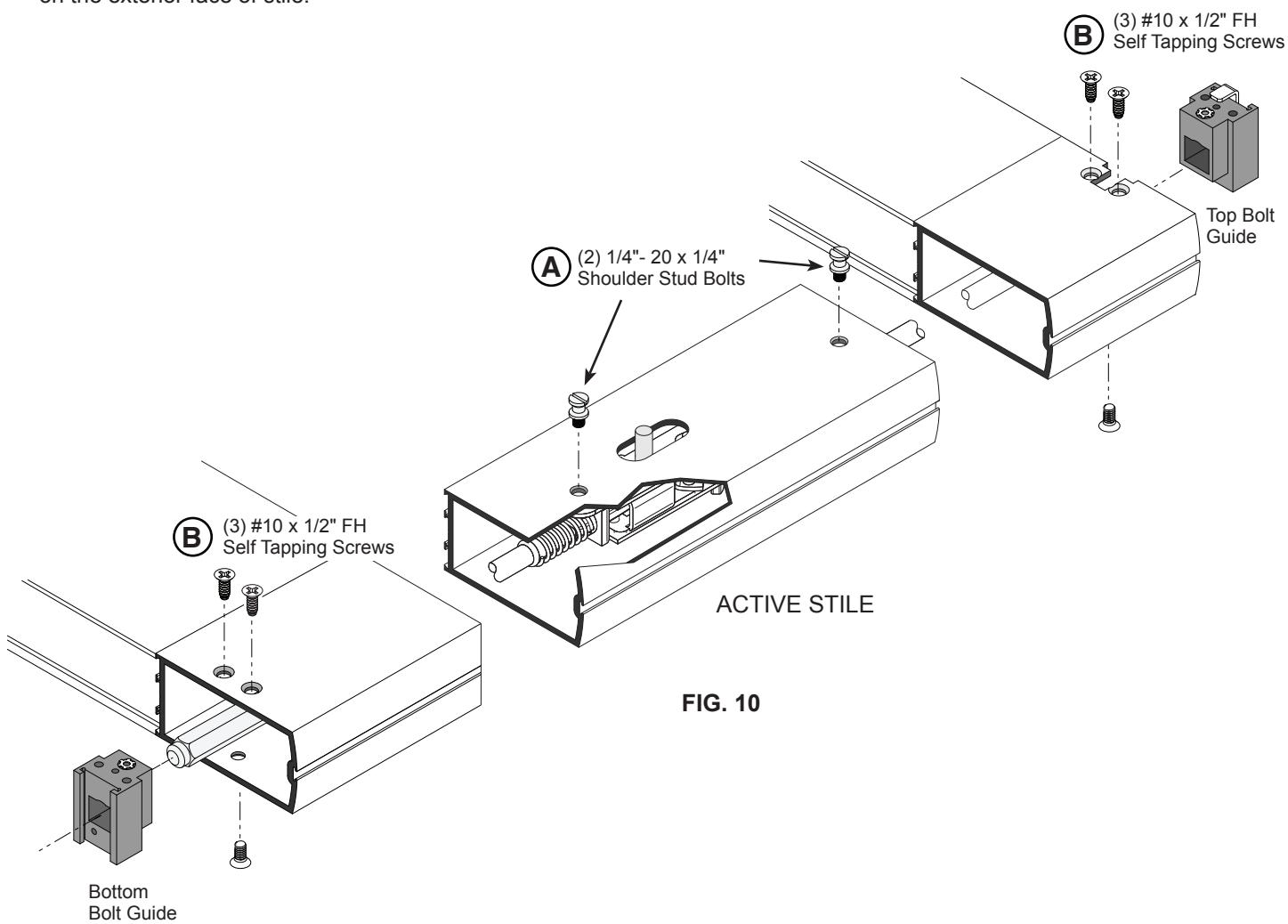
- 1. Insert the panic device rod and case assembly into active stile (Fig. 9).
- 2. Align actuator pin through the slotted cut-out on interior face of stile, fastening with (2) 1/4"- 20 x 1/4" shoulder stud bolts (Fig. 10). A
- 3. Adjust top and bottom rod guide bolts, to extend 1/2" past the frame on both top and bottom stiles.
- 4. Install the top bolt guide assembly (3) #10 x 1/2" FH self tapping screws at both the top and bottom of active door stile. (2) holes on the interior face of stile and (1) hole on the exterior face of stile. B
- 5. Install the bottom bolt guide assembly (3) #10 x 1/2" FH self tapping screws at both the top and bottom of active door stile. (2) holes on the interior face of stile and (1) hole on the exterior face of stile. B
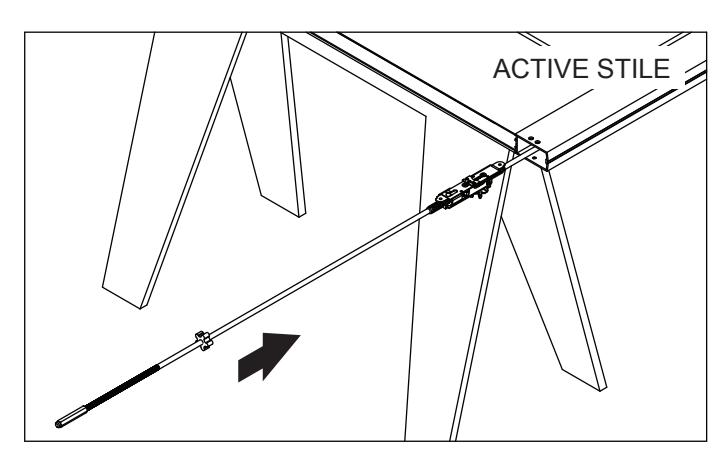
FIG. 9
NOT TO SCALE
INSTALL OPTIONAL MORTISE CYLINDER
- 1. Insert Mortise DL2170 into Mortise Cylinder Mounting Pad 30821J and secure with Cylinder Lock Ring (Included) (Fig. 11). M
- 2. Attach to exterior Active Stile with (2) #8 x 2" FHMS. H
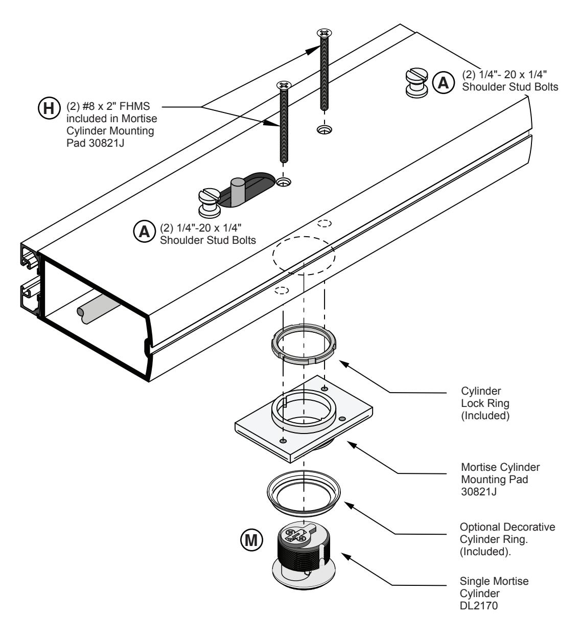
FIG. 11
INSTALL BODY AND ARM ASSEMBLIES
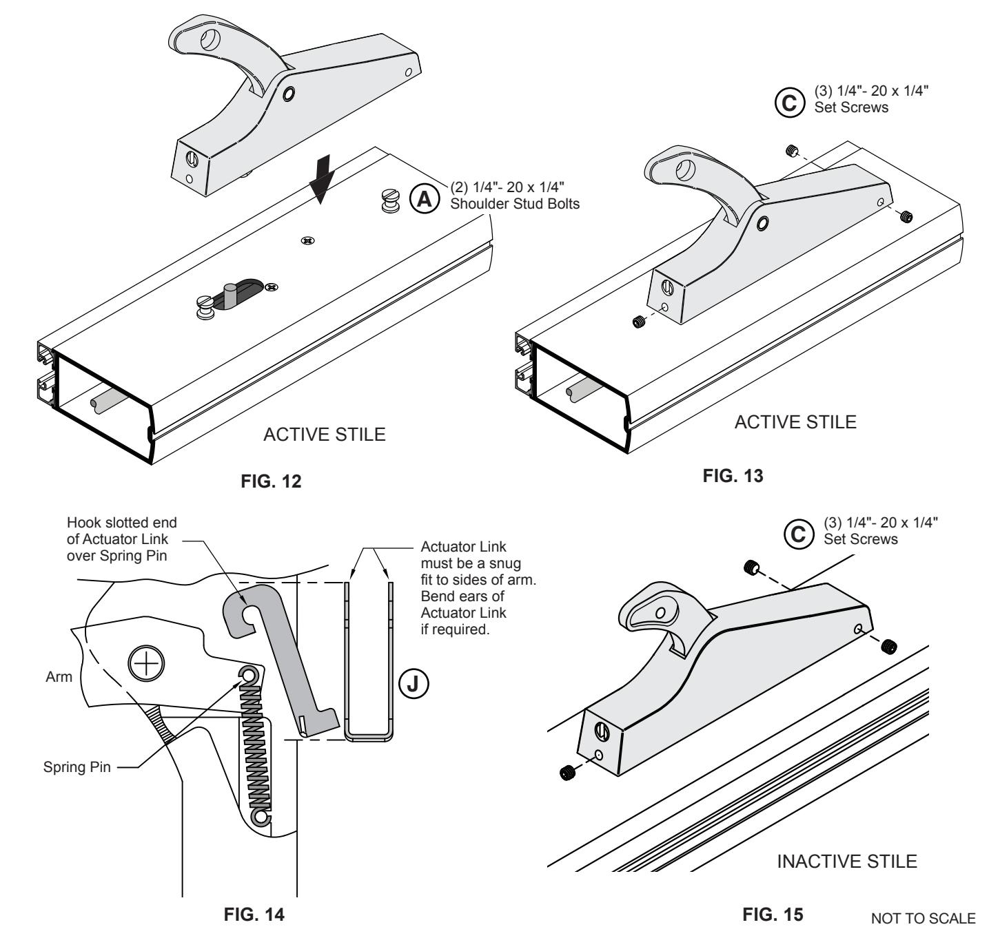
- 1. Insert the (2) 1/4"- 20 x 1/4" Shoulder Bolts on both Active and Inactive Stiles (Fig. 12). A
- 2. Attach Active Body and Arm Assembly using (3) 1/4"- 20 x 1/4" Set Screws (Fig. 13). C
- 3. Attach Actuator Link, hook slotted end of Actuator Link over Spring Pin (Fig. 14). J
- 4. Attach Inactive Body and Arm Assembly using (3) 1/4"- 20 x 1/4" Set Screws (Fig. 15). C
CUT AND INSTALL PANIC BAR DOOR HARDWARE INSTALLATION (CONTINUED)
CRITICAL NOTE:
Panic Bar must be cut within 1/16" (1.6 mm) of correct size to fit and work properly.
- 1. Measure the Panic Bar from the inside edge of the left side body arm assembly to the inside edge of the right side body arm assembly as shown in (Fig. 16).
- 2. Cut and debur the Panic Bar to dimension "A" (Fig. 16).
- 3. Loosen the inactive body and arm assembly, insert panic bar into the arm cavities then secure arm assemblies.
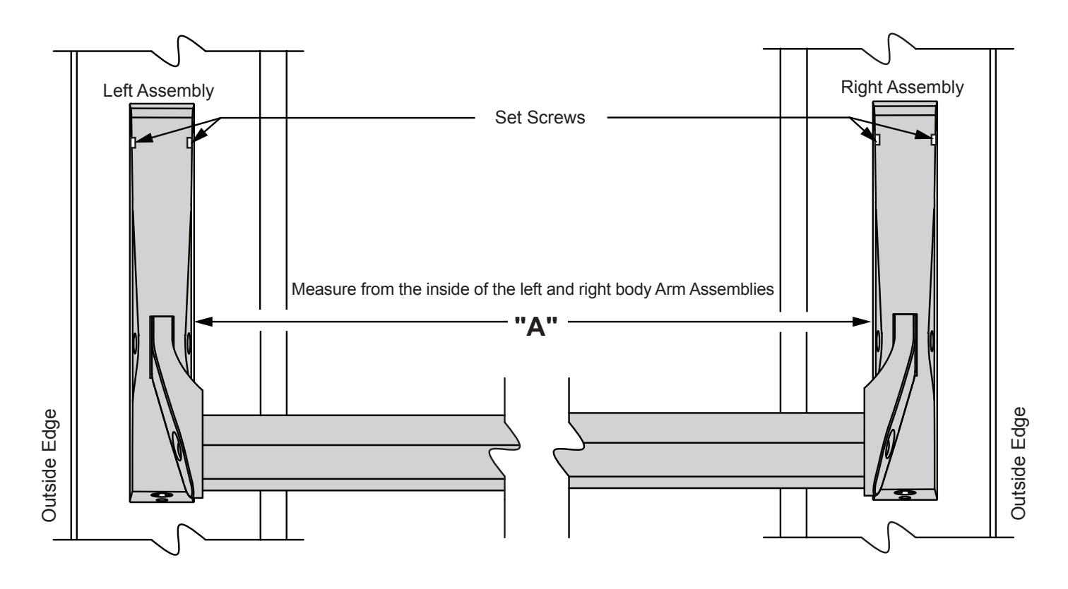
FIG. 16
INSTALL 1085P PADDLE VERSION (HANDED)
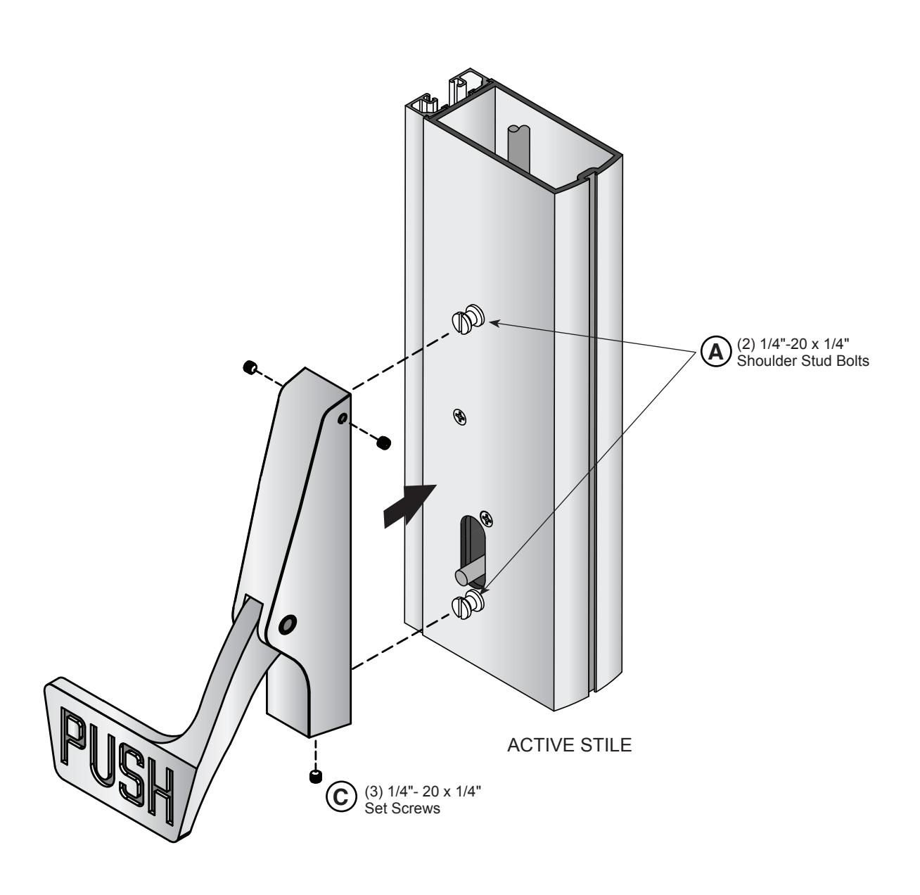
FIG. 17
INSTALL OPTIONAL HANDLE TRIM DOOR HARDWARE INSTALLATION (CONTINUED)
NOTE: Handle Trim must be installed before Panic Exit Device or Paddle.
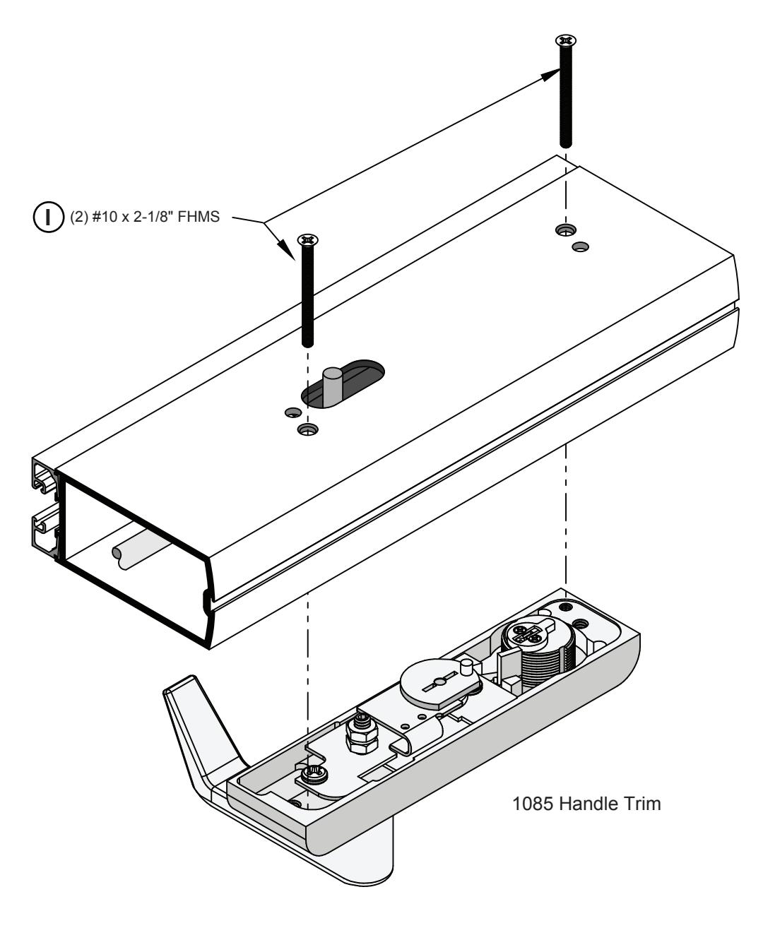
FIG. 18
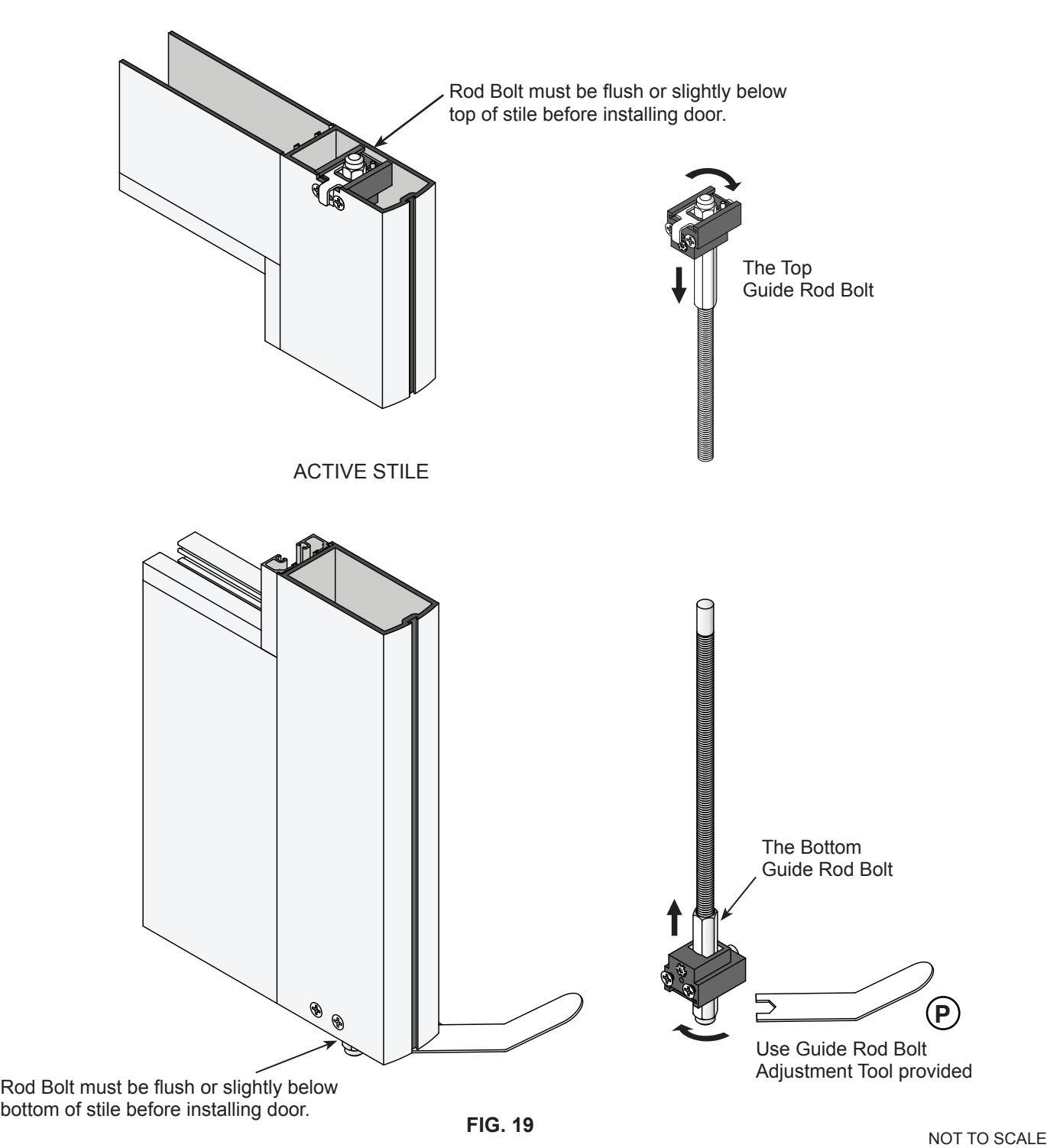
DOOR HARDWARE INSTALLATION (CONTINUED) RETRACT TOP AND BOTTOM ROD BOLTS
Retract the Top Guide Rod Bolt by turning clockwise. Repeat the procedure for the Bottom Guide Rod Bolt. Both should be flush or slightly below the stile end.
DOOR INSTALLATION
- 1. After Rod Bolts are adjusted (retracted), depress the handle and dog in the closed position.
- 2. Install the door and attach to closer (if required).
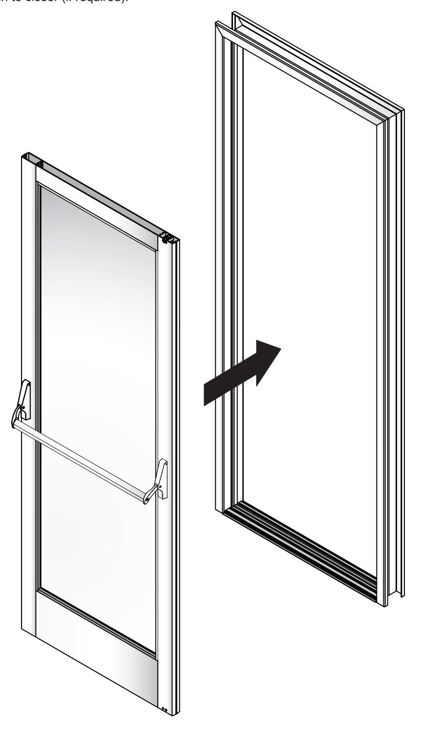
FIG. 20
FRAME PREPARATION
EXTERIOR
HEADER AND THRESHOLD PREPARATION
*WARNING: Hump Strike Plate must be used for proper operation.
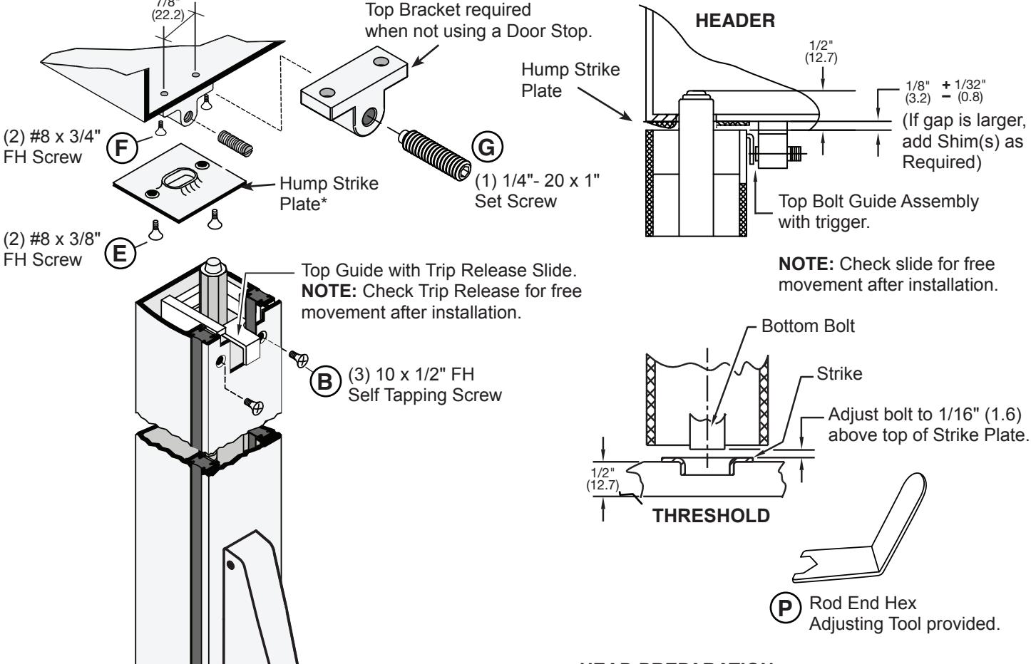
HEAD PREPARATION
- 1. With Door closed in a relaxed position, extend Guide Rod Bolt and mark Header.
- 2. Hold Strike in place and mark Guide Rod Bolt receiver hole and screw holes.
- 3. Drill and notch Stile.
- 4. Attach hardware as illustrated.
THRESHOLD PREPARATION
- 1. Extend Rod Guide Bolt and mark Threshold.
- 2. Hold Bottom Strike in place and mark Guide Rod Bolt receiver hole and screw holes.
- 3. Drill and notch Stile.
- 4. Attach Bottom Strike as illustrated.
NOT TO SCALE
crlaurence.com | usalum.com
FIG. 21
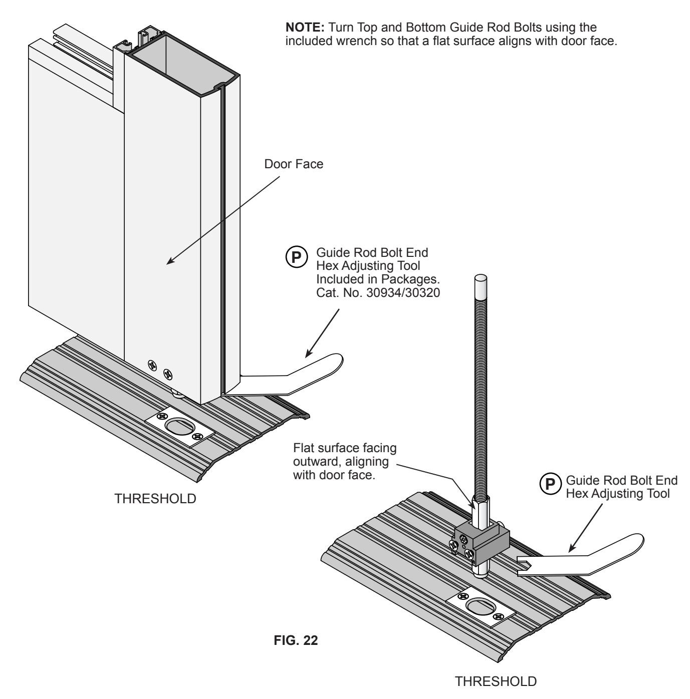
NOTE: Flat Surface of
parallel to Door Stile.
INTERIOR
Rod Bolt must face outward after final adjustment,

GUIDE ROD BOLT FINAL ADJUSTMENT
- 1. With the panic device fully depressed, turn Bottom Guide Rod Bolt clockwise to extend downward past bottom edge of the door. With Rod Adjustment tool, set rod height at 1/16" (1.6) above bottom Strike Plate. In a fully closed and relaxed panic condition, Rod Guide should extend 3/8" (9.5) into threshold strike.
- 2. With panic bar fully depressed, adjust the Top Guide Rod Bolt 1/16" (1.6) and not to exceed 1/8" (3.2) gap from header. In a fully closed and relaxed panic condition the Top of upper Rod Bolt will extend into header 3/8" (9.5).
DOGGING PIN OPTIONS
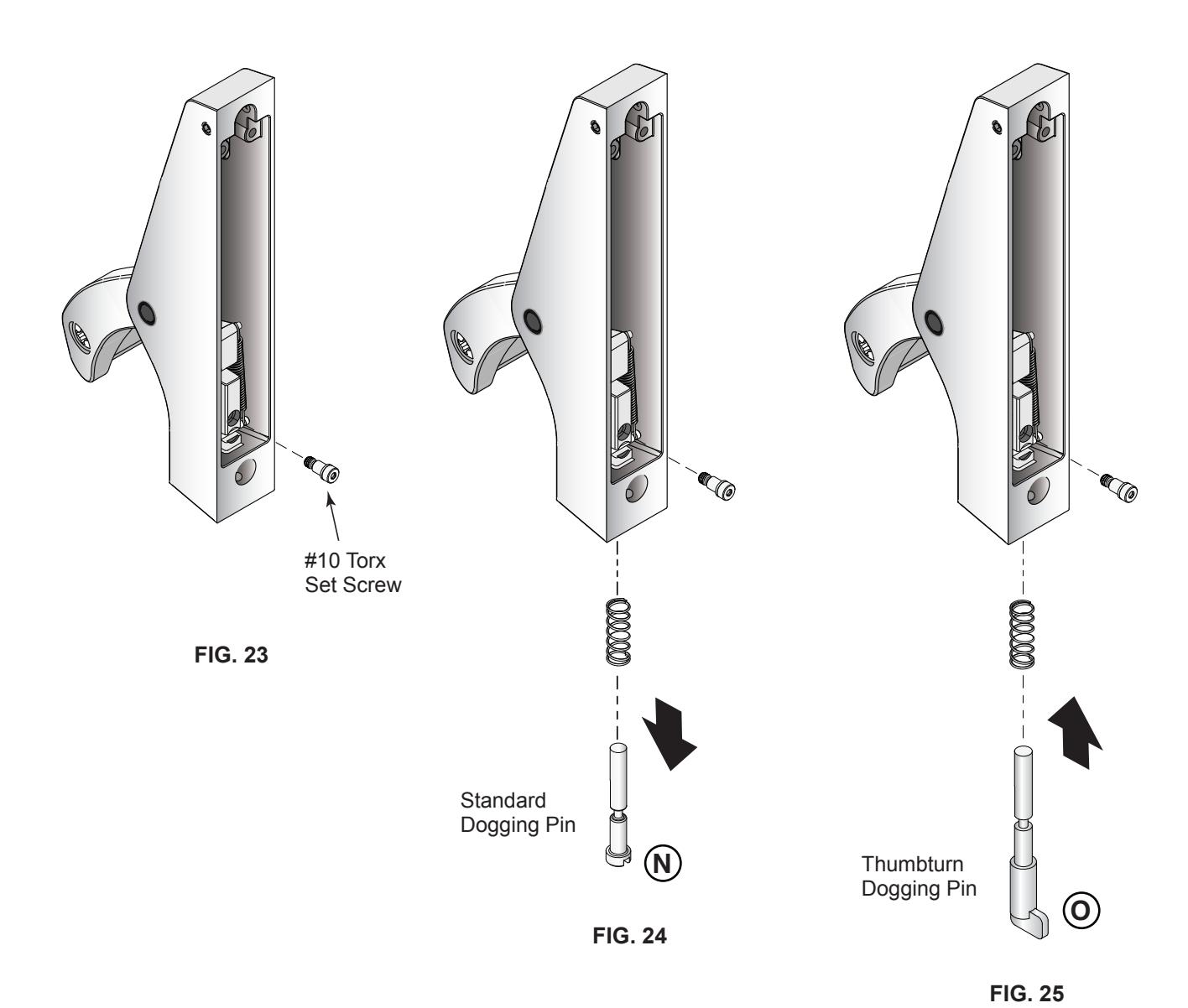
REMOVING STANDARD DOGGING PIN, REPLACE WITH THUMBTURN DOGGING PIN
- 1. Depress Handle and remove the #10 Torx Set Screw. (Fig. 23).
- 2. Remove Standard Dogging Pin as shown (Fig. 24).
- 3. Depress Handle, insert new Thumbturn Dogging Pin and Spring. Lock down with #10 Torx Set Screw, then release Handle. (Fig. 25).
PACKAGED PARTS AVAILABLE
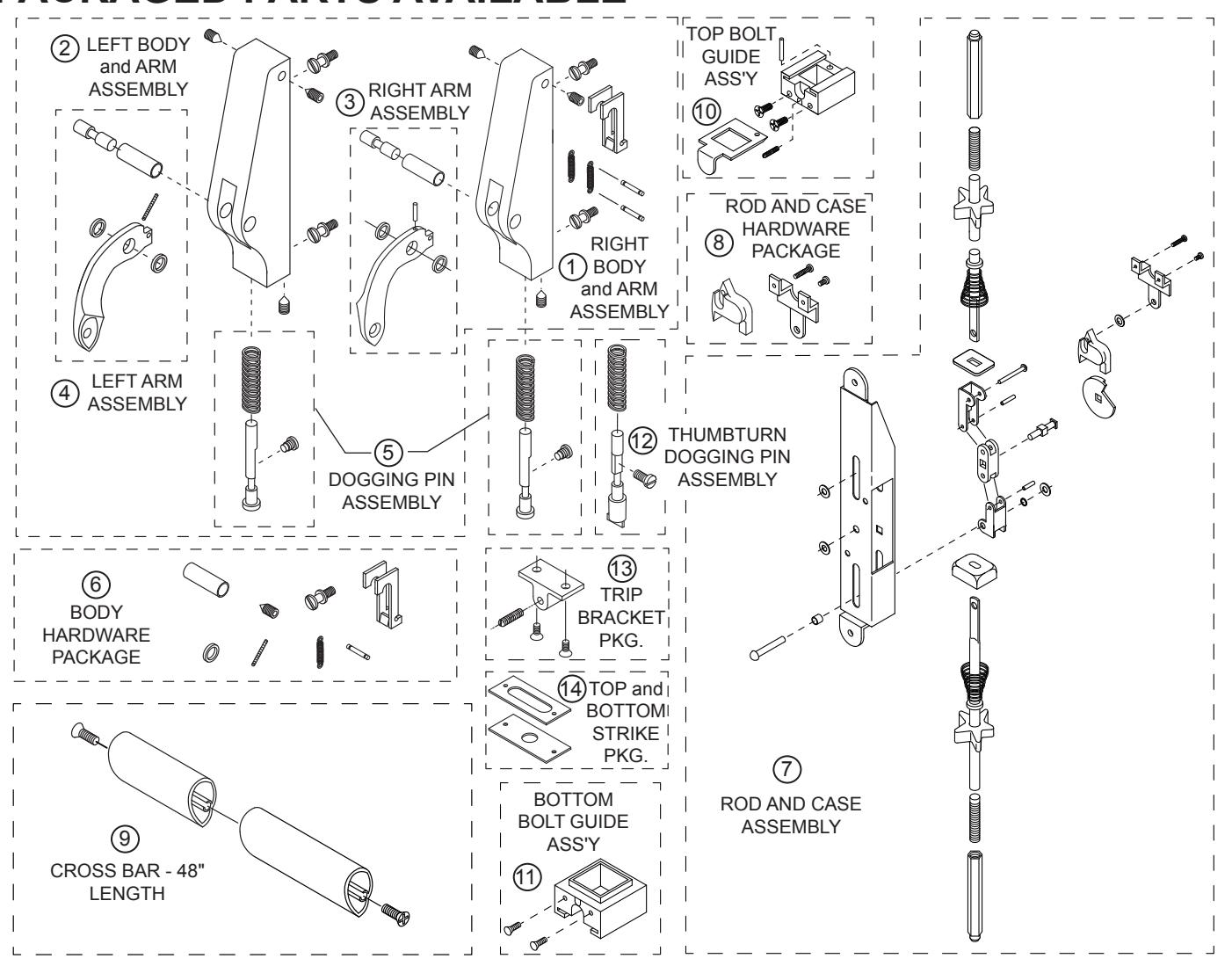
| Assembly No. | Part No. | Description |
|---|---|---|
| 1 | 30982 | RIGHT SIDE BODY AND ARM ASSEMBLY |
| 2 | 30983 | LEFT SIDE BODY AND ARM ASSEMBLY |
| 3 | 301243 | RIGHT SIDE ARM ASSEMBLY |
| 4 | 301242 | LEFT SIDE ARM ASSEMBLY |
| 5 | 301115 | STANDARD DOGGING PIN ASSEMBLY |
| 6 | 301409 | BODY HARDWARE PACKAGE |
| 7 | 30915J | ROD AND CASE ASSEMBLY - 7/0 |
| 8 | 30916 | ROD AND CASE HARDWARE PACKAGE |
| 9 | 30733PKG | 48" (1219 mm) CROSSBAR WITH SCREWS |
| 10 | 30934 | TOP BOLT GUIDE ASSEMBLY |
| 11 | 30320 | BOTTOM BOLT GUIDE ASSEMBLY |
| 12 | 301117 | DOGGING PIN ASSEMBLY - THUMBTURN |
| 13 | 30824 | TRIP BRACKET PACKAGE |
| 14 | 301084 | STRIKE PACKAGE - TOP AND BOTTOM |
PACKAGED PARTS AVAILABLE
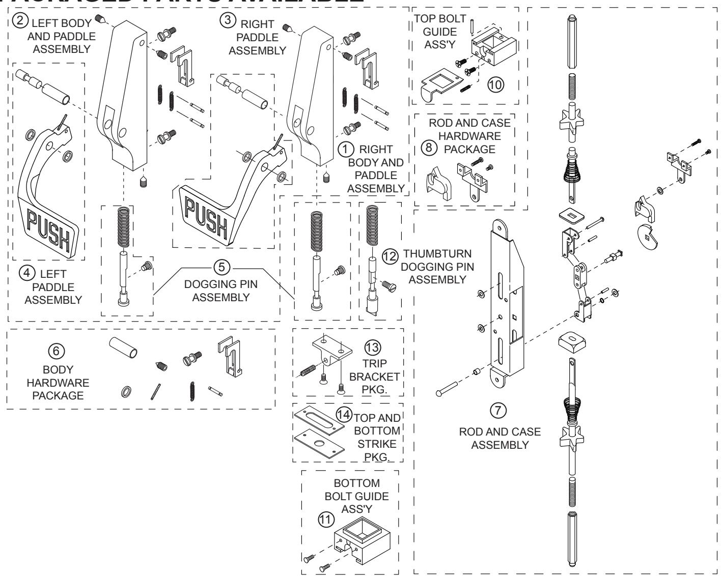
| Assembly No. | Part No. | Description |
|---|---|---|
| 1 | 30984 | RIGHT SIDE BODY AND PADDLE ASSEMBLY |
| 2 | 30985 | LEFT SIDE BODY AND PADDLE ASSEMBLY |
| 3 | 301258 | RIGHT SIDE PADDLE ASSEMBLY |
| 4 | 301259 | LEFT SIDE PADDLE ASSEMBLY |
| 5 | 301115 | STANDARD DOGGING PIN ASSEMBLY |
| 6 | 301409 | BODY HARDWARE PACKAGE |
| 7 | 30915J | ROD AND CASE ASSEMBLY - 7/0 |
| 8 | 30916 | ROD AND CASE HARDWARE PACKAGE |
| 10 | 30934 | TOP BOLT GUIDE ASSEMBLY |
| 11 | 30320 | BOTTOM BOLT GUIDE ASSEMBLY |
| 12 | 301117 | DOGGING PIN ASSEMBLY - THUMBTURN |
| 13 | 30824 | TRIP BRACKET PACKAGE |
| 14 | 301084 | STRIKE PACKAGE - TOP AND BOTTOM |