Instructions for installing KP10G77 Line Bored Locks (Battery Operated Keypad)
Open the original PDF document
View PDF


KP Series 10G77 Keypad 10 Line Lock Installation & Programming Instructions
A7113F
02/21
Table of Contents
| 1 |
Regulatory Compliance
3 |
|
|---|---|---|
| 2 | Warning3 | |
| 3 | General Description4 | |
| 4 |
Specifications
4 |
|
| 5 |
Features
4 |
|
| 6 |
Parts Breakdown
5 |
|
| 7 |
Installation Instructions
8 |
|
| 8 | Programming Instructions16 | |
| 9 | Troubleshooting22 |
Regulatory Compliance
Changes or modifications to this unit not expressly approved by the party responsible for compliance could void the user's authority to operate the equipment.
FCC:
This equipment has been tested and found to comply with the limits for a Class B digital device, pursuant to Part 15 of the FCC Rules. These limits are designed to provide reasonable protection against harmful interference in a residential installation. This equipment generates, uses, and can radiate radio frequency energy and, if not installed and used in accordance with the instructions, may cause harmful interference to radio communications. However, there is no guarantee that interference will not occur in a particular installation. If this equipment does cause harmful interference to radio or television reception, which can be determined by turning the equipment off and on, the user is encouraged to try to correct the interference by one or more of the following measures:
- · Reorient or relocate the receiving antenna.
- Increase the separation between the equipment and receiver.
- Connect the equipment into an outlet on a circuit different from that to which the receiver is connected.
- Consult the dealer or an experienced radio/TV technician for help.
Industry Canada:
This Class B digital apparatus meets all requirements of the Canadian Interference Causing Equipment Regulations. Operation is subject to the following two conditions: (1) this device may not cause harmful interference, and (2) this device must accept any interference received, including interference that may cause undesired operation.
Cet appareillage numérique de la classe B répond à toutes les exigences de l'interférence canadienne causant des règlements d'équipement. L'opération est sujette aux deux conditions suivantes: (1) ce dispositif peut ne pas causer l'interférence nocive, et (2) ce dispositif doit accepter n'importe quelle interférence reçue, y compris l'interférence qui peut causer l'opération peu désirée.
This equipment complies with FCC radiation exposure limits set forth for an uncontrolled environment. This equipment should be installed and operated with minimum distance 20cm between the radiator and your body. This transmitter must not be co-located or operating in conjunction with any other antenna or transmitter.
Cet équipement est conforme aux limites d'exposition aux radiations de la FCC définies pour un environnement non contrôlé. Cet équipement doit être installé et utilisé à une distance minimale de 20 cm entre le radiateur et votre corps. Cet émetteur ne doit pas être co-localisé ou fonctionner en conjonction avec une autre antenne ou un autre émetteur.
Under Industry Canada regulations, this radio transmitter may only operate using an antenna of a type and maximum (or lesser) gain approved for the transmitter by Industry Canada. To reduce potential radio interference to other users, the antenna type and its gain should be so chosen that the equivalent isotropically radiated power (e.i.r.p.) is not more than that necessary for successful communication.
Conformément à la réglementation d'Industrie Canada, le présent émetteur radio peut fonctionner avec une antenne d'un type et d'un gain maximal (ou inférieur) approuvé pour l'émetteur par Industrie Canada. Dans le but de réduire les risques de brouillage radioélectrique à l'intention des autres utilisateurs, il faut choisir le type d'antenne et son gain de sorte que la puissance isotrope rayonnée équivalente (p.i.r.e.) ne dépasse pas l'intensité nécessaire à l'établissement d'une communication satisfaisante.
2
Warning

This product can expose you to lead which is known to the state of California to cause cancer and birth defects or other reproductive harm. For more information go to: www.P65warnings.ca.gov.
Ce produit peut vous exposer au plomb qui, dans l'état de la Californie, est reconnu pour causer le cancer, des anomalies congénitales ou d'autres problèmes de reproduction.
Pour plus d'informations, visitez: www.P65warnings.ca.gov.

Any retrofit or other field modification to a fire rated opening can potentially impact the fire rating of the opening, and SARGENT Manufacturing makes no representations or warranties concerning what such impact may be in any specific situation. When retrofitting any portion of an existing fire rated opening, or specifying and installing a new fire-rated opening, please consult with a code specialist or local code official (Authority Having Jurisdiction) to ensure compliance with all applicable codes and ratings.
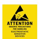
To avoid possible damage from electrostatic discharge (ESD), some basic precautions should be used when handling electronic components:
- Minimize build-up of static by touching and/or maintaining contact with unpainted metal surfaces such as door hinges, latches, and mounting plates especially when mounting electronic components such as readers and controllers onto the door.
- Leave components (reader and controller) protected in their respective anti-static bags until ready for installation
- Do not touch pins, leads or solder connections on the circuit boards

3 General Description
The SARGENT Keypad 10 Line Lock is designed for areas which require standalone authorized entry. It is a self-contained microprocessor-controlled keypad with non-volatile memory.
The keypad will hold a total of 99 different User Codes. User Codes "01" and "03" are utilized for Master Code and Supervisory Code, respectively. All programming is done at the keypad, with over 1,100,000 possible user combinations.
This lock is operated by four (4) "C" batteries.
4 Specifications
- Latch bolt 1/2" standard
- 3/4" available (41-prefix)
- Deadlocking latch
- Outside lever controlled by keypad or key retracts latch bolt
- Inside lever retracts latch
- Locks furnished for 1-3/4" doors only
- U.L. Listed
- Battery operated with (4) each "C" Alkaline
- Tactile keypad made of ultraviolet stable material
- Non-volatile memory
- Low battery alert 4 chirps after code entry
- Option Code available to sound horn every time keypad is pressed
- External remote "request to enter" connector requires wire harness (52-2071)
- All programming done at keypad
5 Features
- Non-volatile memory
- Motor driven, battery-operated bored lock
- Battery operated with (4) each "C" Alkaline
- Typical 40,000 operations per set of batteries
- Low battery alert 4 chirps after code entry
- Option Code available to sound horn every time keypad is pressed
- External remote "request to enter" connector requires wire harness (52-2071)
- All programming done at keypad
- LED's indicate valid or invalid entries
- Green LED indicates unlocked.
- Yellow LED indicates unit is in programming mode
- Flashing green and yellow LED's indicate deadbolt thrown or lock set is in passage mode
- Operates utilizing any two to six digits per code. Digits may be repeated and codes may start with zero
- Adjustable unlock time
- Entry of three wrong User Codes disables all codes for ten seconds. Green LED flashes.
- Piezo horn can be heard with each keystroke or turned off by Master or Supervisory Code
- Last 15 transactions can be output to printer via Data Transfer Device (DTD)
- 99 users total: (1) Master Code, (1) Emergency Code, (1) Supervisory Code, with the rest being standard codes, passage codes, or one time only codes
Parts Breakdown 6
| ITEM |
PART NUMBER
DESCRIPTION |
NO.
REQ'D |
|
|---|---|---|---|
| 1 | *10-0523 | "B" Inside lever/regular and 30- | 1 |
| *10-2204 | "J" Inside lever/regular and 30- | 1 | |
|
*10-0503
"L" Inside lever/regular and 30- |
1 | ||
|
*10-0547
"P" Inside lever/regular and 30- |
1 | ||
|
*10-0536
"B" Inside lever/75 handicap warning |
1 | ||
| *10-2247 | "J" Inside lever/75 handicap warning | 1 | |
| *10-0514 | "L" Inside lever /75 handicap warning | 1 | |
| *10-0558 | "P" Inside lever/75 handicap warning | 1 | |
| See SARGENT web page for Costal Series Levers. | |||
| 2 | *10-0790 | Rose scalp "G" | 2 |
| 2A | *10-0798 | Rose scalp "L" | 2 |
| 4 | 10-0792 | Spacer bushing | 2 |
| 5 | 10-3048 | Inside rose spring assembly ( not finished) | 1 |
| 6 | 01-9170 | Through-bolt screws | 2 |
| 6A | 10-0802 | Plastic screw holder | 2 |
| 7 | 01-4388 | 8 X 1 SELF TAP SCREW | 1 |
| 7A | 82-0443 | Turn lever cover plate, plastic -black. not shown | |
| 9 | *10-2875 | Inside escutcheon assembly | 1 |
| 9A | 52-6085 | Replacement Inside Controller Assembly Kit | 1 |
| 10 | 45-1340 | Flat head screw ( security) | 1 |
| 10A | 52-0069 | Battery cover only | 1 |
| 11 | 1/8" security hex wrench (not provided) | ||
| 12 | *52-2340 | Outside escutcheon & keypad | |
| 12A |
52-2299
Keypad assembly only |
1 | |
| 13 | 01-1500 | SELF TAP SCREW TYPE "AB" | |
| 14 | 52-0033 | Fire stop plate and screws | 1 |
* Specify Finish
Copyright © 2014. 2021, Sargent Manufacturing Company, an ASSA ABLOY Group company. All rights reserved. Reproductions in whole or in part without express written permission of Sargent Manufacturing Company is prohibited. 02/28/21
6 Parts Breakdown (Continued)
| ITEM |
PART
NUMBER |
DESCRIPTION |
NO.
REQ'D |
|
|---|---|---|---|---|
| 15 | 10-2642 | 77 Lockbody (std, 10, 21, 23, 30, SC, SE, VA & VS prefixes only) | ||
| 15A | 10-2643 | 77 Lockbody ( 60, 63, 64 prefixes only) | ||
| 15B | 10-2644 | 77 Lockbody ( 70, 72, 65-73, 65-73P lockbody) | ||
| 16 | 10-3049 | Outside rose spring assembly ( not finished) | 1 | |
| 17 | 10-0019 | Cylinder spacer | 1 | |
| 17A | 13-3613 | Schlage ( SC) cylinder ( provide keying details) | 1 | |
| 17B | 13-3614 | Schlage ( SE) cylinder ( provide keying details) | 1 | |
| 17C | 13-3713 | Cylinder ( 10-Signature) | 1 | |
| 18 | 10-0312 | Cylinder retainer | 1 | |
| 18A | 10-0313 | Cylinder retainer for removable core, Interchangeable core & Keso | 1 | |
| 19 | 13-3266 | Cylinder ( standard) provide keying details | 1 | |
| 20 | *10-2251 | "B" Lever outside standard cylinder | 1 | |
| *10-2205 | "J" Lever outside standard cylinder | 1 | ||
| *10-0502 | "L" Lever outside standard cylinder | 1 | ||
| *10-0546 | "P" Lever outside standard cylinder | 1 | ||
| *10-0525 | "B" Outside lever/30-competitive cylinder | 1 | ||
| *10-2206 | "J" Outside lever/30-competitive cylinder | 1 | ||
| *10-0503 | "L" Outside lever/30-competitive cylinder | 1 | ||
| *10-0547 | "P" Outside lever/30-competitive cylinder | 1 | ||
| *10-0535 | "B" Outside lever/standard cylinder 76 handicap warning | 1 | ||
| *10-2246 | "J" Outside lever/standard cylinder 76 handicap warning | 1 | ||
| *10-0513 | "L" Outside lever/standard cylinder 76 handicap warning | 1 | ||
| *10-0557 | "P" Outside lever/standard cylinder 76 handicap warning | 1 | ||
| See SARGENT web page for Costal Series Levers. | ||||
| 21 | Key ( provided with cylinder) | A/R | ||
| 22 | *10-2000 | 2-3/4" Backset latch ( standard) | 1 | |
| 22A | 10-2053 | 3-3/4" Backset latch ( 23 prefix) | 1 | |
| 22B | *10-2058 | 5" Backset latch ( 25 prefix) | 1 | |
| 22C | *10-2634 | 3/4" Throw ( 41 prefix) | 1 | |
| 23 | 01-4414 | Screw for standard front and strike | 4 | |
| 24 | *08-0312 | #800 Strike | 1 | |
| 24A | *08-0066 | #808 Strike ( 28-prefix) | 1 | |
| 25 | *10-2052 | Screw pack- standard (screws (latch, strike, #3) & push pin tool) | 1 | |
| *10-2070 | Screw pack- 28- prefix (screws (front, strike, #3) &push pin tool) | 1 | ||
| 26 | 52-2057 | Screw pack ( includes #'s 7, 11, 13, 14, 28, 28A, 29) | 1 | |
| 27 | 08-0055 | Strike Box- standard | 1 | |
| 28 | 01-9674 | 8-32UNC-2A X 1 1/2" PH PAN HD MACH SCREW | ||
| 28A | 01-9063 | WASHER | 1 | |
| 29 | 77-0168 | 8-32UNC-2A X 1 7/8" PH FL HD MACH SCREW | 1 | |
| 30 | 10-0043 | Lever Retainer Push Pin, Not Shown | 1 | |
* Specify Finish
6 Parts Breakdown (Continued)
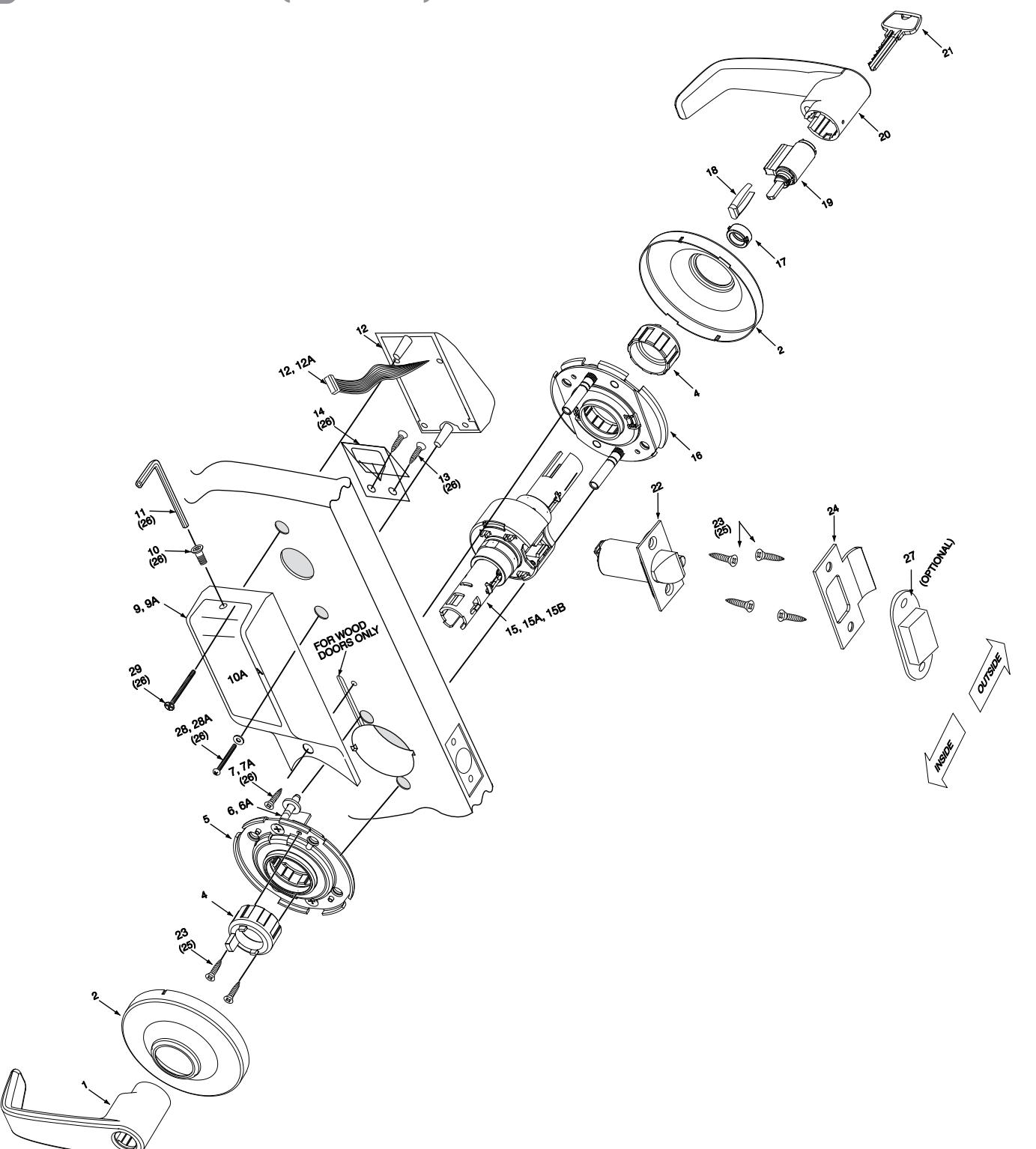

7 Installation Instructions
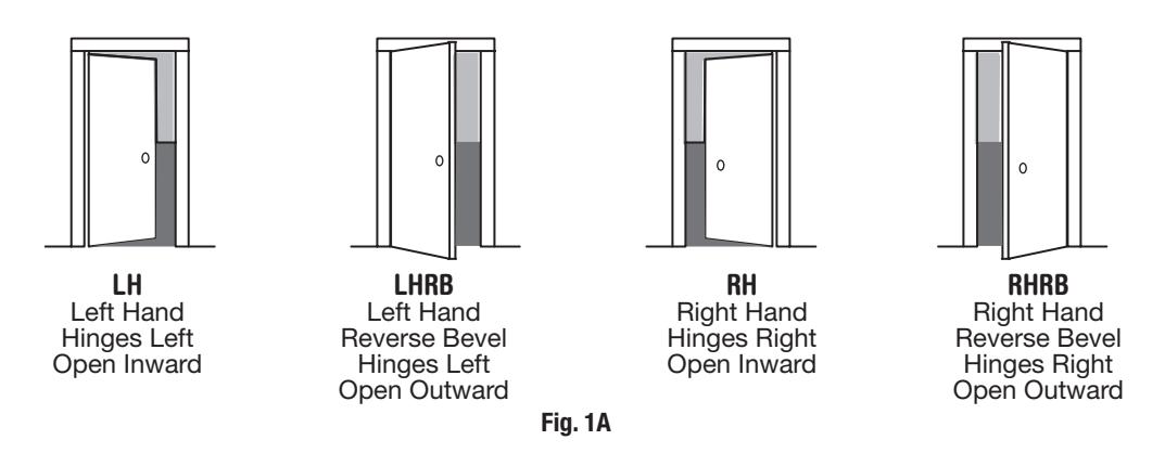
Step #1 – Verify Hand and Bevel of Door
Stand on outside/locked side of door when determining the door hand
Step #2 Door Preparation
Prepare door according to appropriate template (see website www.sargentlock.com):
- For metal door template, see 4486 and 4494
- For wood door template, see A7332 (scale paper template ships with product) and 4375-1
- Prior to installation, all holes must be free of burrs, debris and sharp edges
- If doors are not properly reinforced per ANSI115.2, commercially available reinforcements should be installed
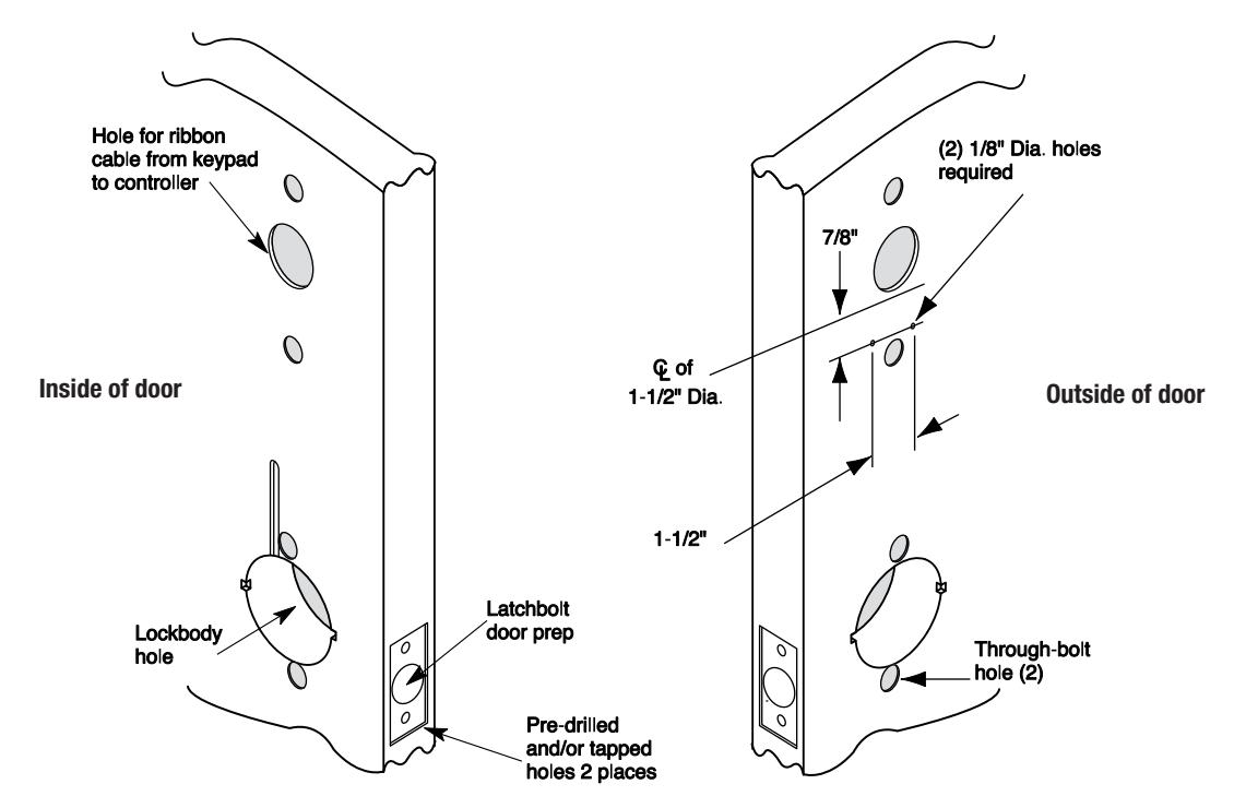
Fig. 1B Wood Door Preparation
Step # 3 – Frame Preparation for Strike
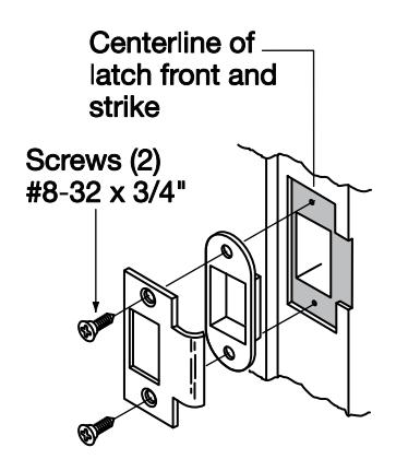
Step #4 Latch and Fire Stop Plate Installation
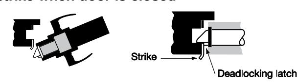
- 1. Install latch with beveled bolt facing the strike
- 2. Attach with two screws, but DO NOT tighten completely at this time
- 3. Attach Fire Stop Plate with two screws
Note: Required for all Fire Rated doors Fire Rated Doors– Install Fire Stop Plate (P/N 52-0033) as shown below:
Outside of door (2) 1/8" Dia. holes reauired 0 7/8" Fire Ç of stop plate 1-1/2" Dia Slot 1-1/2" (2) Self tapping screws #8 x 1/2" long for wood Through-bolt hole (2)
Important: Latch bevel must match door bevel and deadlocking latch must stop on strike when door is closed
Non Fire Rated Exterior Hollow Metal Doors* Install Weather Conduit supplied with Weatherization Kit (P/N 52-6084) as shown below:
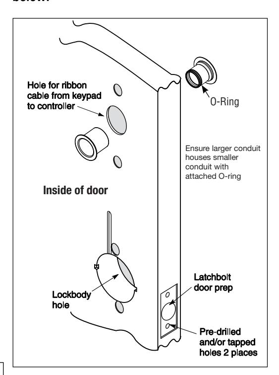
*Install conduit if exterior door is directly exposed to the weather, if it's a hollow metal (open core) type door. It's not required on solid core doors. If rain water enters open web at top of door, the conduit prevents water from inside of door entering onto controller or keypad.
Copyright © 2014, 2021, Sargent Manufacturing Company, an ASSA ABLOY Group company. All rights reserved Reproductions in whole or in part without express written permission of Sargent Manufacturing Company is prohibited.
Step #5 - Install Lock Body
Lock Preset to:
- Through-bolt location- 12 & 6 o'clock
- Door thickness- 1-3/4" thick- see below for other door conditions
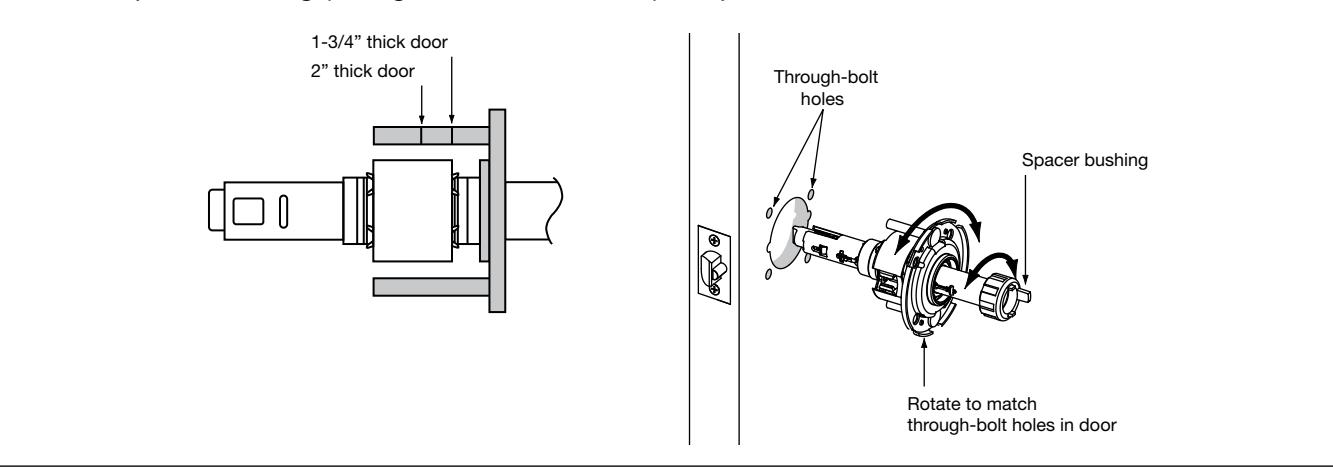
Adjustment for different through-bolt and door thickness:
-
Remove outside lever (usually keyed), scalp and spacer bushing
- Rotate mounting plate to either align with through-bolt holes in door, or adjust for proper door thicknesses (see markings on through-bolt)
- Reinstall spacer bushing (to align with back of lever) scalp and lever
- 1. Feed wires into the lock body hole from outside of door
- 2. Install lock body into cross-bore hole from outside of the door (locked side)
3. Lock body must engage both the latch unit prongs and tail piece (as shown)
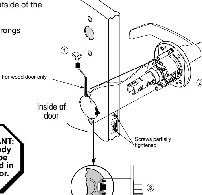
IMPORTANT:
Door must remain open during installation. Use door stop.
IMPORTANT: Lockbody must be centered in the door.

Step #6 - Securing the Lock to the Door
- 1A. If wood door, feed wires up through the routed channel as shown
- 1B. If metal door, feed wire connector within the door core and out hole on inside of door
- 2. Attach inside rose assembly and spacer bushing and secure with screws shown
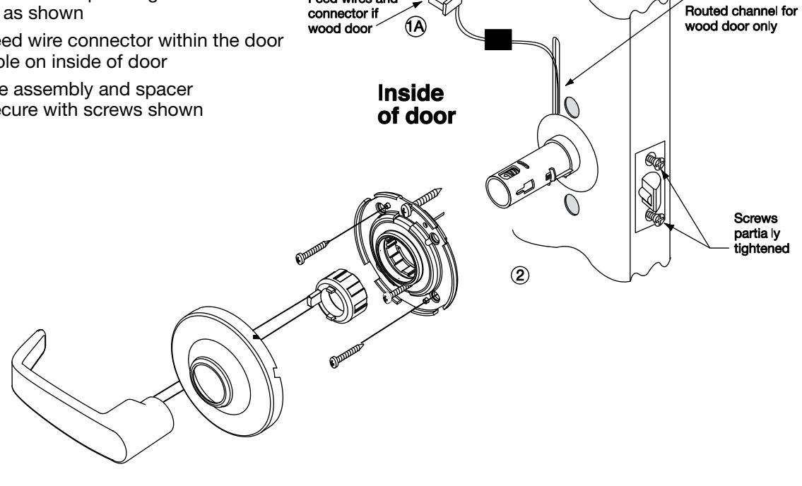
Feed wires and
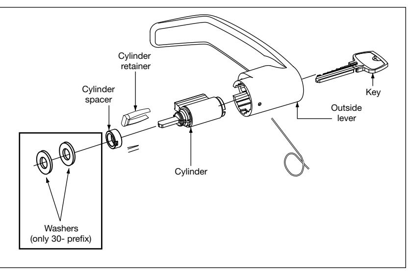
How to Change Cylinder (if required)
- 1. With outside lever in hand use standard pliers; pull out cylinder retainer
- 2. Remove key and cylinder from lever
- 3. Insert new cylinder
- 4. Secure by pressing cylinder retainer flush with shelf*
*NOT SHOWN
Step #7 – Install (Optional)* Weatherseal Gasket & Shroud
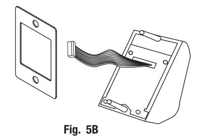
- 1. Carefully remove adhesive backing from the gasket (Fig. 5A).
-
2. Apply gasket to escutcheon:
- Starting in one place, press the adhesive side of the gasket firmly against the escutcheon.
- Work around the escutcheon, pressing the sticky side of the gasket firmly against the escutcheon edge.
- The gasket should be aligned so that all edges of the escutcheon are covered.
- 3. Attach escutcheon to the door.
Note: The 43 cylinder may be used with or without a gasket.
*For exterior doors and supplied with Weatherization Kit (p/n 52-6084). Additional supplied shroud (not shown) is required if outside keypad escutcheon is directly exposed to weather.
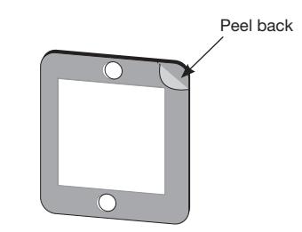
Fig. 5A
Step #8 Installation of Outside Escutcheon
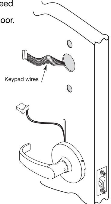
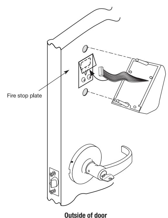
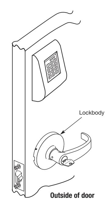
• From the outside of the door, feed keypad wires through fire stop plate and to the inside of the door. Lift plate cover if needed.
• IMPORTANT - Fire stop plate cover must lay flat before installing the keypad to avoid interference
Copyright © 2014, 2021, Sargent Manufacturing Company, an ASSA ABLOY Group company. All rights reserved. Reproductions in whole or in part without express written permission of Sargent Manufacturing Company is prohibiteo
Inside of door
Step #9 – Securing the Outside Escutcheon
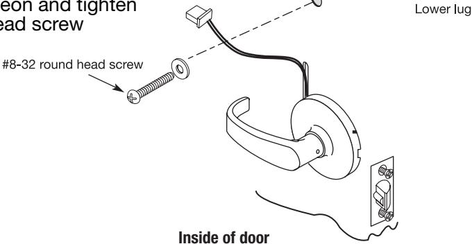
- From the inside of the door, use the #8-32 x 1 1/2" round head screw with the flat washer to attach the escutcheon thru the lower lug
- Straighten escutcheon and tighten the #8-32 round head screw
Step #10 – Installation of Inside Escutcheon
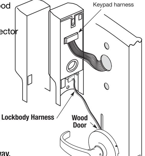
Plug the smaller lockbody wires into the inside escutcheon. Access holes vary based on wood or metal door application.
Plug keypad ribbon cable connector into inside escutcheon
Inside of door
IMPORTANT :
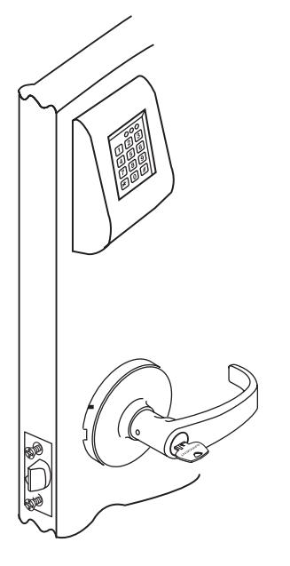
Both wire plug connectors go on only one way. Do not offset the connectors. If not seated, keypad will not function properly.
Outside of door
Copyright © 2014. 2021, Sargent Manufacturing Company, an ASSA ABLOY Group company. All rights reserved. Reproductions in whole or in part without express written permission of Sargent Manufacturing Company is prohibited.
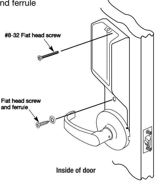
Step #11 - Securing Inside Escutcheon
- Remove black plastic battery cover with 1/8" security hex wrench
- Carefully tuck the wire into the routed groove in wood door. The remainder can fit within bottom portion of escutcheon. Make certain that wires are not pinched by obstructions in escutcheon.
- Place inside escutcheon flat against the door
- Secure inside escutcheon with one flat head screw thru interior of inside escutcheon and into post of exterior escutcheon
- · Secure bottom of escutcheon with flat head screw and ferrule
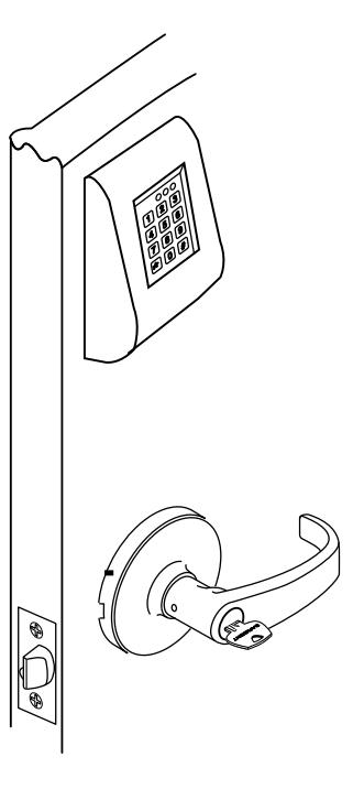
Step #12 Test Lockset
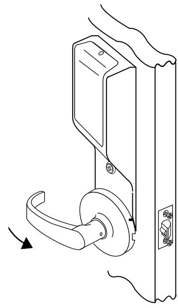
- Rotate inside lever to test for latch bolt retraction
- Place key into cylinder and rotate key for latch bolt retraction
- Tighten latch bolt screws on edge of door
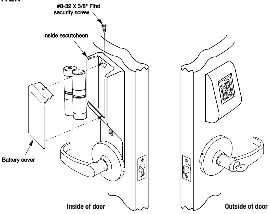
Step #13 – Battery Installation
- Place (4) C batteries into the compartment as indicated inside escutcheon
- Attach battery cover to inside escutcheon and secure with #8-32 x 3/8" security screw
DO NOT OVERTIGHTEN
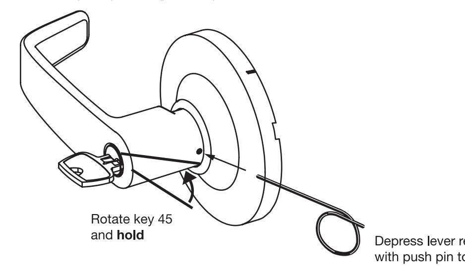
How to Remove Outside Lever Only
- 1. Insert key, rotate 45˚ clockwise and hold
- 2. Depress lever retainer with push pin tool (provided)

8 Programming Instructions
The KP Keypad bored lock can support 99 users. Each user is assigned a User Number in addition to the code used for entry.
Example:
| USER TYPE | USER NUMBER |
USER CODE
(2-6 DIGITS) |
|---|---|---|
| Master | 01 | 1 2 3 4 |
| Emergency | 02 | 2 2 2 2 2 |
| Supervisor | 03 | 3 0 3 0 3 0 |
| Standard | 04-97 | 2 6 5 |
|
Special Factory
10 Sec. Time Preset |
98
99 |
1 3 6 8 |
This Keypad Bored lock has 99 User Codes available for programming purposes.
- The Master Code is always User "01". The Master Code assigns the Emergency and Supervisory Codes. It is also used for programming and will override the deadbolt * . Users are deleted through the Master Programming Code only.
- The Emergency Code is always User "02". The Emergency Code will override the deadbolt * in the lock and has an unlock time of 10 seconds.
- The Supervisory Code is always User "03". The Supervisory Code allows temporary lockout of selected users, changes duration of unlock time, requests infrared interrogation output, and may add additional User Codes.
- The first User Code will be User "04" or higher. User numbers do not have to be used or entered sequentially.
- User codes "98" and "99" have a factory-set unlock time of ten seconds. This allows a handicapped person extra time which would not be required by other users.
Initial Set-Up Procedures:
The following are typical procedures** to follow when setting up your KP Series Keypad:
- If a mistake is made during any of procedures, depress the " * " several times until the yellow LED goes out.
- If no keystroke is made in a 30-sec time frame the programming up to that point will default and you will have to start over.
To Begin Programming:
The Keypad bored lock is preset at the factory with Master Code "1234". Entering "1234 * " will unlock the lock allowing the lever handle to retract the latchbolt.

8 Programming Instructions (Continued)
All of the following procedures start with 99#.
If after the last " * " is depressed, the yellow LED does not go out, depress " * " once more.
Change Master Code:
- 1234 * (Yellow LED Begins to Blink Slowly) This example uses the Factory Default Master Code
- 50# 1# 01# New Master Code * (Yellow LED Blinks Quickly)
- New Master Code * (Yellow LED Blinks Slowly) * (Yellow LED Goes Out)
To Enter the Emergency Code: (Unlock Duration is Factory Set at 10 Sec)
- Master Code * (Yellow LED Begins to Blink Slowly)
- 50# 1# 02# Emergency Code * (Yellow LED Blinks Quickly)
- Emergency Code * (Yellow LED Blinks Slowly) * (Yellow LED Goes Out)
To Enter the Supervisory Code:
- Master Code * (Yellow LED Begins to Blink Slowly)
- 50# 1# 03# Supervisory Code * (Yellow LED Blinks Quickly)
- Supervisory Code * (Yellow LED Blinks Slowly) * (Yellow LED Goes Out)
To Enter a User Code:
- Supervisory or Master Code * (Yellow LED Begins to Blink Slowly)
- 50# 1# User Number (04-97)# User Code * (Yellow LED Blinks Quickly)
- User Code * (Yellow LED Blinks Slowly) * (Yellow LED Goes Out)
To Enter a Passage (Maintained Mode) Code:
When Passage Mode is used, the same User Code must be used to re-lock the lock.
- Supervisory or Master Code * (Yellow LED Begins to Blink Slowly)
- 50# 2# User Number (04-97)# User Code * (Yellow LED Blinks Quickly)
- User Code * (Yellow LED Blinks Slowly) * (Yellow LED Goes Out)
To Enter a One Time User Code:
- Supervisory or Master Code * (Yellow LED Begins to Blink Slowly)
- 50# 3# User Number# User Code * (Yellow LED Blinks Quickly)
- User Code * (Yellow LED Blinks Slowly) * (Yellow LED Goes Out)

8 Programming Instructions (Continued)
All of the following procedures start with 99# (continued). If after the last " * " is depressed, the yellow LED does not go out, depress "*" once more.
To Deactivate "Beep" With the Depression of Each Key:
- Supervisory or Master Code * (Yellow LED Begins to Blink Slowly)
- 30# 0# 0# (Yellow LED Continues to Blink Slowly)
- • * (Yellow LED Blinks Quickly)
- • * (No Beep on Depression and Yellow LED Blinks Slowly)
- • * (No Beep on Depression and Yellow LED Goes Out)
To Reactivate "Beep" With the Depression of Each Key:
- Supervisory or Master Code * (Yellow LED Begins to Blink Slowly)
- 30# 0# 1# (Yellow LED Continues to Blink Slowly)
- • * (Yellow LED Blinks Quickly)
- • * (Beep on Depression and Yellow LED Blinks Slowly)
- • * (Beep on Depression and Yellow LED Goes Out)
To Clear the Entire Memory:
- Master Code * (Yellow LED Begins to Blink Slowly)
- 46# 00000# 00000# (Yellow LED Continues to Blink Slowly)
- • * (Yellow LED Blinks Quickly)
- • * (No Beep on Depression and Yellow LED Goes Out)
- PAUSE, Yellow LED Begins to Blink Again
- • * (Yellow LED Goes Out)
NOTE This Deletes ALL Codes, including Master, Emergency and Supervisory. The Master Code is set back to 1234, Door Number to 0001 and Unlock time to 5 Sec. If the Master Code is not known, Factory Assistance will be required to clear the memory. 1-800-810-WIRE.
To Program Door Numbers into Keypad:
- Master Code * (Yellow LED Begins to Blink Slowly)
- 43# 0# Door Number# (must be four digits) (Yellow LED Blinks Slowly)
- • * (Yellow LED Begins to Blink Quickly)
- • * (Yellow LED Blink Slowly)
- • * (Yellow LED Goes Out)
8 Programming Instructions (Continued)
Chain Programming
When programming multiple User Numbers and Codes into the Keypad Exit Device, it is not necessary to leave and re-enter the programming Mode (50) for each entry. Multiple entries may be chained together and the three different types of user codes (Standard, Passage and One time) may be mixed.
The format to be used is as follows where:
"T" is the Type of user code with "1" Standard, "2" Passage and "3" One Time.
"UN_" is User Number (04-99).
"UC_" is User Code (2 to 6 digits) which correlates with user Number.
99# Master or Supervisor Code * 50# Type# User Number a# User Code a * User Code a * T# UNb# UCb * UCb * T# UNc# UCc * UCc * ……T# UN_# UC_ * UC_ **
An example with four user codes is shown below:
| Type | User Number | User Code |
|---|---|---|
| 1 | 05 | 875 |
| 3 | 12 | 2226 |
| 2 | 08 | 5444 |
| 1 | 50 | 3367 |
Using Master Code 4732 and above information, the keypad exit device would be programmed as follows:99# 4732 * 50# 1# 05# 875 * 875 * 3# 12# 2226 * 2226 * 2# 08# 5444 * 5444 * 1# 50# 3367 * 3367 **
If all user codes are the same type, it is not necessary to enter the type number with each entry. The type number only hasto be entered with the first user code. The format now simplifies to:
99# Master or Supervisor Code * 50# Type# User Number a# User Code a * User Code a * UNb# UCb * UCb * UNc# UCc * UCc * ……UN_# UC_ * UC_ **
An example with three user codes is shown below:
| Type | User Number | User Code | |
|---|---|---|---|
| 1 | 07 | 77 | |
| 1 | 15 | 67832 | |
| 1 | 91 | 7568 | |
Using Master Code 45988 and above information, the keypad exit device would be programmed as follows: 99# 45988 * 50# 1# 07# 77 * 77 * 15# 67832 * 67832 * 91# 7568 * 7568 **
To chain the User Number delete procedure: 99# Master Code * User Number a# ** UNb# ** UNc# ** ……UN_# ***
Using the information from the above example: 99# 45988 * 07# ** 15# ** 91# ***
Reproductions in whole or in part without express written permission of Sargent Manufacturing Company is prohibited. 02/28/21
KP Series Keypad 10 Line Lock

8 Programming Instructions (Continued)
All of the following procedures start with 99# (continued).
If after the last " * " is depressed, the yellow LED does not go out, depress " * " once more.
To Interrogate Transaction Log (to output last 15 entries):
- Supervisory or Master Code * (Yellow LED Begins to Blink Slowly)
- 70# 0# 0# (Yellow LED Blinks Slowly)
- • * (Yellow LED Begins to Blink Quickly)
- Set DTD to printer mode
- Select 'Infrared Capture'
- Press Enter key on DTD
- Hold DTD between 1 to 3 inches from the KP keypad infrared LED (top right side LED on keypad). Press Enter key on DTD.
- • * (Yellow LED Begins to Blink Slowly or alternately) IR LED will begin broadcasting data, and the DTD will retrieve door transaction log.
Note: Retrieving the transaction log takes approximately 20 seconds, after 20 seconds continue to next step
* (Yellow LED Goes Out)
For additional information, see "Transaction Log".
Note: Seq. # 1 is the programming request to output the entries. Sequence numbers 2-5 are the actual entries.
To Reset / Clear Transaction Log
- Master Code * (Yellow LED Begins to Blink Slowly)
- 76# 00000# 00000# (Yellow LED Blinks Slowly)
- • * (Yellow LED Begins to Blink Quickly)
- • * (Yellow LED Goes Out)
Transaction Log
Door Number
- 4 Digits
- Up to 9999 different doors, assigned by user
Transaction Number
- Single digit 1-5
- Latest transaction 1
- Oldest transaction 5
User Number
- Three digits 001 through 099
- User numbers assigned at time of programming
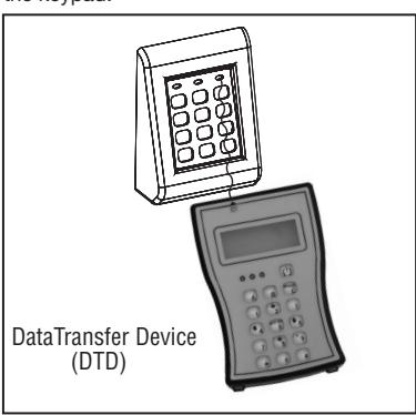
Hold Data Transfer Device (DTD) up to the (top right side) infrared LED as shown. DTD can be used to download information from the keypad.
| Door # 5666 | |||||
|---|---|---|---|---|---|
| Door Number | Seq | User | Trans | ||
| 1 | 001 | 003 | |||
| 2 | 003 | 005 | |||
| 3 | 003 | 005 | |||
| 4 | 020 | 005 | |||
| 5 | 003 | 005 | |||
|
Transaction
Number |
User Number |
Transaction
Type* |
|||
*Transaction Types
003 = Log transaction started 005 = 5 second unlock time**
Transaction Types
- 003 = Log transaction started
- 005 = 5 second unlock time*
*Note: The Unlock Time is Adjustable for Momentary Operation. A (5)-second unlock time is recommended to extend battery life.
Once the unlock time is entered, it is the same for ALL users except 02, 98 and 99 which are factory set for 10 seconds.

8 Programming Instructions (Continued)
To Delete a User Number:
- Master Code * (Yellow LED Begins to Blink Slowly)
- User Number# (Yellow LED Blinks Slowly)
- • * (Yellow LED Begins to Blink Quickly)
- • * (Yellow LED Blinks Slowly)
- • * (Yellow LED Goes Out)
To Disable / Enable a User Number:
- Supervisory or Master Code * (Yellow LED Begins to Blink Slowly)
- 56# 0# = Enable, 1# = Disable User Number# (04-99) (Yellow LED Blinks Slowly)
- • * (Yellow LED Begins to Blink Quickly)
- • * (Yellow LED Blinks Slowly)
- • * (Yellow LED Goes Out)
All of the following procedures start with 99# (continued).
If after the last " * " is depressed, the yellow LED does not go out, depress "*" once more.
To Set Unlock Time:
- Master Code * (Yellow LED Begins to Blink Slowly)
- 85# Time Duration# (01-99 Sec) 0# (Yellow LED Blinks Slowly)
- • * (Yellow LED Begins to Blink Quickly)
- • * (Yellow LED Blinks Slowly)
- • * (Yellow LED Goes Out)
Optional Equipment
- Data Transfer Device (DTD) used to download the user and transaction type.
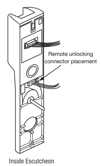
- Remote Unlocking 52-2071 (has a 2-pin connector with 2 wires). When wired to a remote normally open momentary switch, a momentary switch closure is used used for remote unlocking of keypad 10 Line lock.
02/28/21 Copyright © 2014. 2021, Sargent Manufacturing Company, an ASSA ABLOY Group company. All rights reserved. Reproductions in whole or in part without express written permission of Sargent Manufacturing Company is prohibited.

9 Troubleshooting Instructions
Note: The following tests are used to check basic functionality of the keypad and inside controller.
Power On Self Test (POST) for new KP controllers only (released after 1/2021)
- Immediately after installing the batteries, verify the following keypad sequence:
- Green LED flashes quickly (5) times a second
- Yellow LED flashes quickly (5) times a second
- Beeps 3 times quickly (3) times a second
The following tests are for existing Legacy and New KP controllers and take approximately 1 to 2 seconds each:
- Enter '7890#123456 * ' each key beeps when pressed (if key beep is activated)
- Verify the following keypad sequence: Green LED flash, Yellow LED flash, 3 beeps
If you have the optional DTD
- Set DTD to printer mode, press (center) enter key on DTD once
- Align DTD Infrared port 1 3" from the top right side keypad Infrared transmitting LED
- Press enter key on DTD again just before the * key in the following step
- Enter '7890#123456 * ' each key beeps when pressed (if key beep is activated)
- Verify the following on keypad/DTD sequence: Green LED flash, Yellow LED flash, 3 quick beeps, "IR OK" is displayed on DTD

02/28/21 Copyright © 2014. 2021, Sargent Manufacturing Company, an ASSA ABLOY Group company. All rights reserved. Reproductions in whole or in part without express written permission of Sargent Manufacturing Company is prohibited.

SARGENT Manufacturing Company 100 Sargent Drive New Haven, CT 06511 USA 800-810-WIRE (9473) • www.sargentlock.com
Founded in the early 1800s, SARGENT® is a market leader in locksets, cylinders, door closers, exit devices, electro-mechanical products and access control systems for new construction, renovation, and replacement applications. The company's customer base includes commercial construction, institutional, and industrial markets.
Copyright © 2014. 2021, Sargent Manufacturing Company, an ASSA ABLOY Group company. All rights reserved. Reproduction in whole or in part without the express written permission of Sargent Manufacturing Company is prohibited.