Instructions for Installing 351 Series Door Closers with ‘UH, HZ, HZA, PH9’ Holder Arms
Open the original PDF document
View PDF351 Series
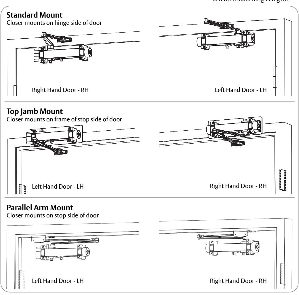
Non Handed Door Closer Standard Mount Top Jamb Mount Parallel Arm Mount
Hold Open Arm Models
Adjustable (Sizes 1-6) 25-H 25-HZ 25-PH9


WARNING
This product can expose you to lead which is known to the state of California to cause cancer and birth defects or other reproductive harm. For more information go to www.P65warnings.ca.gov.
Ce produit peut vous exposer au plomb qui, dans l'état de la Californie, est reconnu pour causer le cancer, des anomalies congénitales ou d'autres problèmes de reproduction. Pour plus d'informations, visitez: www.P65warnings.ca.gov.
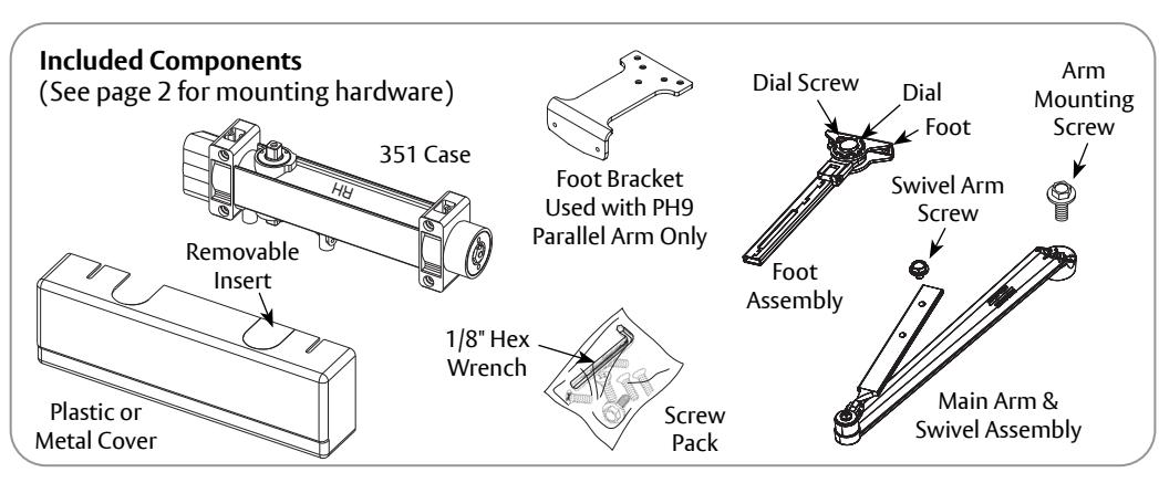

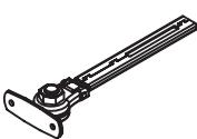
Note: Legacy FHO arm has installation orientation. See 80-9300-0005-000. available online.
H8 Mortise Friction Hold Open Arm
Note: H8 arm is handed same as door. See template A7233, available online.
PH4 Friction Hold Open Arm
Note: PH4 parallel arm is used for flush frame applications. See template A7229, available online.
351 Hold Open Closer

ATTENTION:
An incorrectly installed or improperly adjusted door closer can cause property damage or personal injury. These installation instructions should be followed to avoid the possibility of misapplication or misadjustment.
- For special applications, a separate door and frame preparation template is packed with these instructions. Use this instruction sheet for installation sequence and closer adjustments only.
- Doors should be hung on ball bearing or anti-friction hinges.
- A separate door stop is recommended.
- Always consult door/frame manufacturer for fastener compatibility.
- Door and frame must be properly reinforced.
- Adjust closing time speed between 3 and 6 seconds from 90° to Close. Greater closing times may be required for elderly or handicapped.
- DO NOT install closer on exposed side (weather side) of exterior doors. Warranty will be void.
- Dimensions are given in inches (millimeters).
| *Mounting Hardware | Door or Frame | Drill | |
|---|---|---|---|
|
Case, Foot or Optional PH9 Bracket:
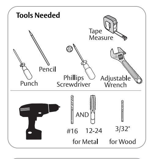
#12 x 1-1/2 Phillips Flat Head Self Drilling Tapping Screw |
Wood | 3/32" (2.38mm) | |
| mmmmm |
Case, Foot or Optional PH9 Bracket:
#12 x 1-1/2 Phillips Flat Head Wood Screw |
||
|
Case, Foot or Optional PH9 Bracket:
#12-24 x 5/8 Phillips Flat Head Machine Screw |
Metal |
Drill #16 (.177)
Tap 12-24 |
|
|
Case and/or Foot:
Mortise Nut (optional) |
Hollow Metal |
1/4" (6.00mm) thru
3/8" (9.50mm) door face opposite to closer |
|
| Aluminum or Wood | 3/8" (9.50mm) thru | ||
* Security Torx screws supplied upon request, not shown
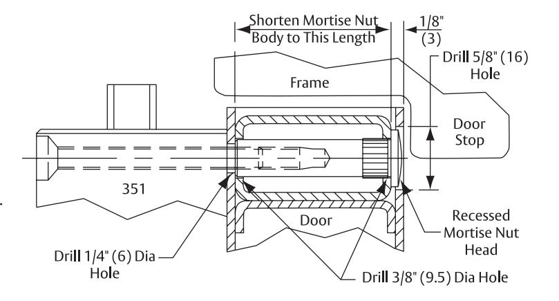
Mortise Nut and Screw Detail
Top jamb application: Door closer foot will be attached to the door in a manner similar to that shown for mounting the case.
Appropriate mortise nuts and screws will be supplied based on door thickness.
Door construction must provide a bridge type reinforcement to prevent the door rail from collapsing when screws are tightened.
If distance between door stop and center of mortise nut head is less than 7/8" (22mm), stop must be cut to clear head or head must be recessed (shown).
Accessories
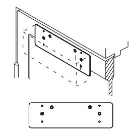
351A Mounting Plate Allows mounting onto a door with a minimum top rail of 2-3/8" (60) or top jamb with 1-3/4" (44) minimum frame clearance
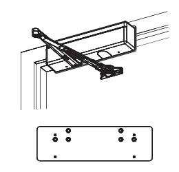
351B Mounting Plate Top Jamb Mount For low ceiling conditions or minimum 1-15/16" (49) frame face
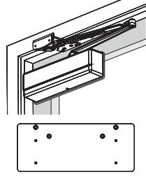
351D Drop Plate Parallel Arm Mount For narrow top rail conditions 3" (76) minimum top rail required
351 Standard Mount - H Arm Installation (Right Hand Shown)
ASSA ABLOY
1. Prepare door and frame.
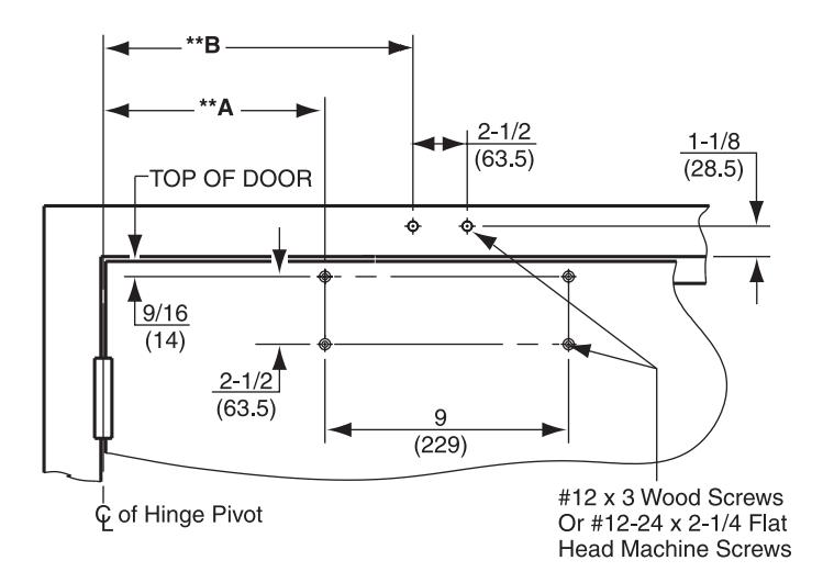
| Arm Type | Mounting |
Max Door
Opening |
**Dim A | **Dim B |
|---|---|---|---|---|
| Н | Standard | 110° |
9-1/2"
(241) |
12-3/4"
(324) |
| Holder | Alternate | *160° |
6-1/2"
(165) |
9-3/4"
(248) |
NOTES:
- 1. IMPORTANT: Use Alternate mounting if door can open beyond limits shown for standard mounting.
- 2. *If butt, frame, and wall conditions permit, door will open 180°.
- 3. ** Dimension is taken from hinge edge of door for invisible hinges. Butt, offset, swing clear, center hung or invisible hinges.
- 4. Use screws provided or use mortise nuts when required. See chart on page 2.
2. Mount case to door.
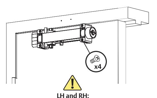
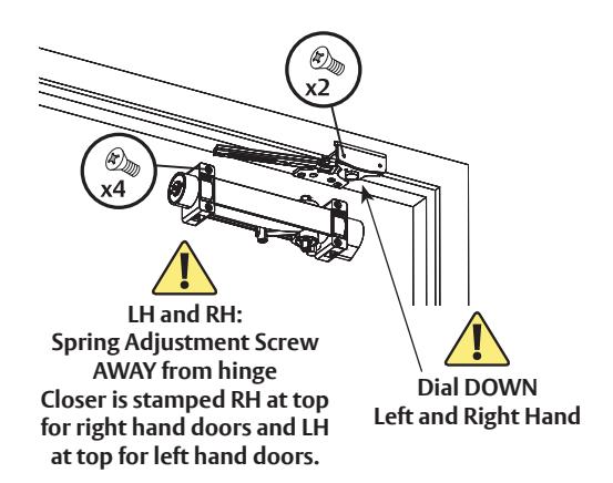
Spring Adjustment Screw AWAY from hinge Closer is stamped RH at top for right hand doors and LH at top for left hand doors.
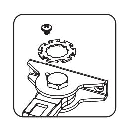
3a. Remove dial from foot.
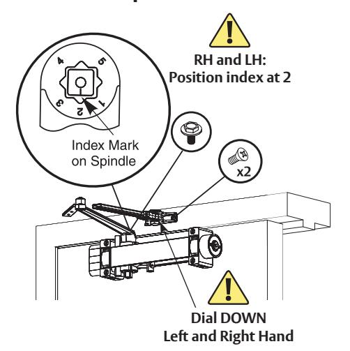
3b. Install separate arms.
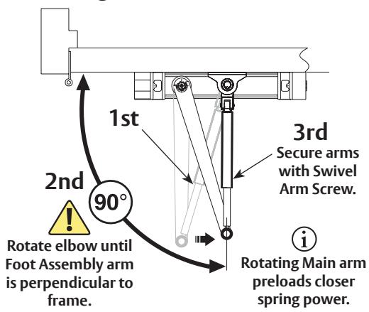
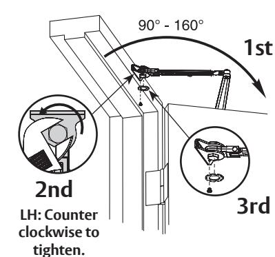
4. Connect arms, preload spring and tighten screw.
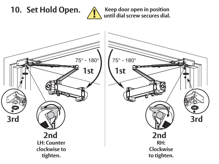
5. Set Hold Open.
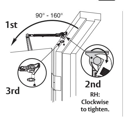
Keep door open in position until dial screw secures dial.
You've installed the 351 Hold Open Closer - Standard Mount.
Go to page 7 for closer adjustments and cover installation.
351 Top Jamb Mount - H, HZ, HZA Arm Installation (Right Hand Shown)
SARGENT
ASSA ABLOY
1. Prepare door and frame.
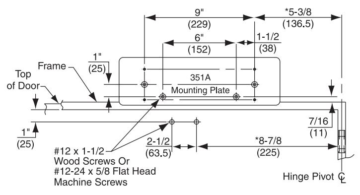
| Arm Type |
Reveal
Depth |
**Door
Opening |
|---|---|---|
| H Arm |
0" to 2"
(0 to 51) |
140° |
| HZ Arm |
2-1/8" to 5"
(54 to 127) |
140° |
| HZA Arm |
5-1/8" to 8"
(130 to 203) |
140° |
NOTES:
- 1. * Dimension is taken from hinge edge of door for invisible hinges.
- 2. ** Door opening to 180° is possible if depth of reveal is not greater than 2" (51).
- 3. 351A Mounting Plate required for double rabbeted frame.
- 4. Use screws provided or use mortise nuts when required. See chart on page 2.
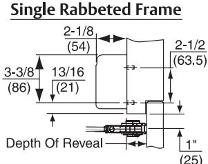
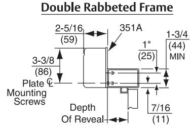
Mount case to frame. Use Mounting Plate if necessary.
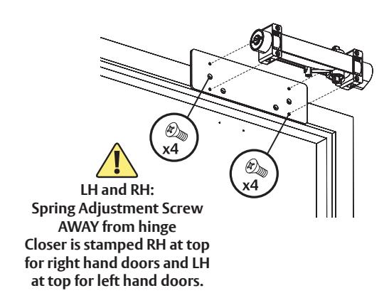
3a. Remove dial from foot.
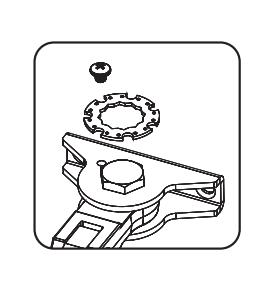
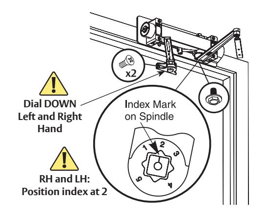
3b. Install separate arms.
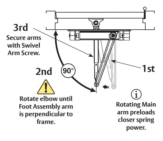
4. Connect arms, preload spring and tighten screw.
5. Set Hold Open.
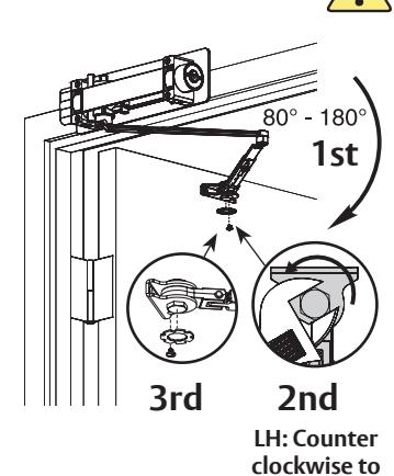
tighten.
Keep door open in position until dial screw secures dial.
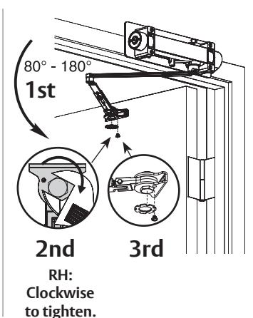
You've now installed the 351 Hold Open Closer - Top Jamb Mount.
Go to page 7 for closer adjustments and cover installation.
351 Parallel Arm Mount - PH9 Arm Installation (Right Hand Shown)
ASSA ABLOY
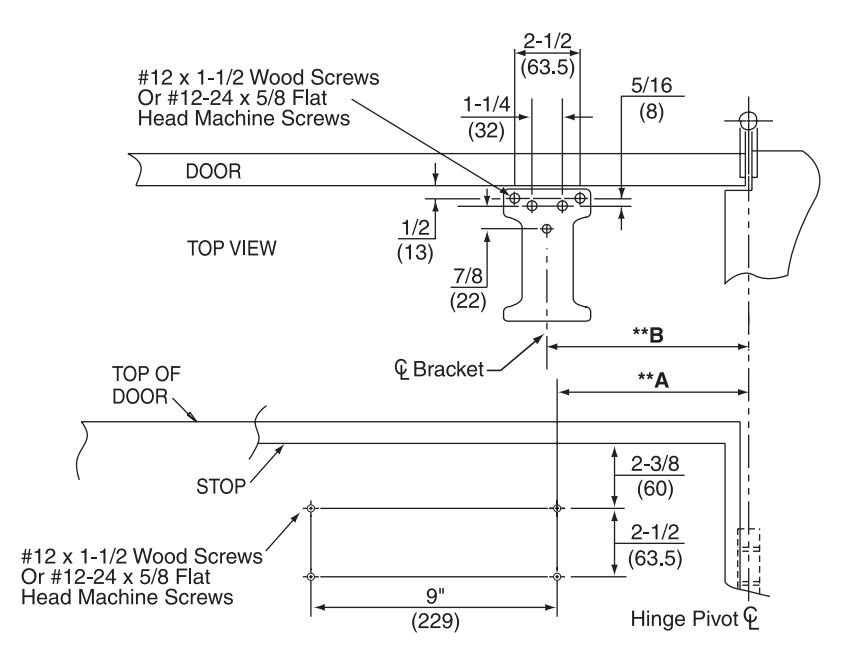
1. Prepare door and frame.
|
Max Door
Opening |
**Dim A | **Dim B |
|---|---|---|
| 120° |
9-7/8"
(251) |
10-1/4"
(260) |
| *180° |
7"
(178) |
7-3/8"
(187) |
NOTES:
- 1. *Do not use this mounting for swing clear hinges.
- ** Dimension is taken from hinge edge of door for invisible hinges.
- 3. Use screws provided or use mortise nuts when required. See chart on page 2.
2. Close latching speed and closing speed valves.
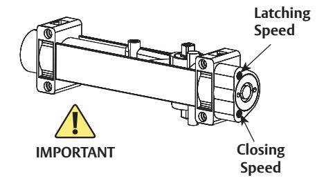
3. Remove dial from foot.
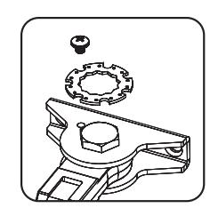
4. Install foot bracket to frame stop.
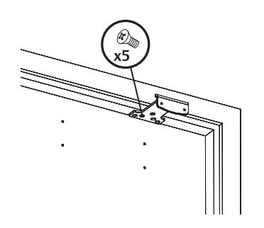
5. Install foot assembly to foot bracket and case to door.
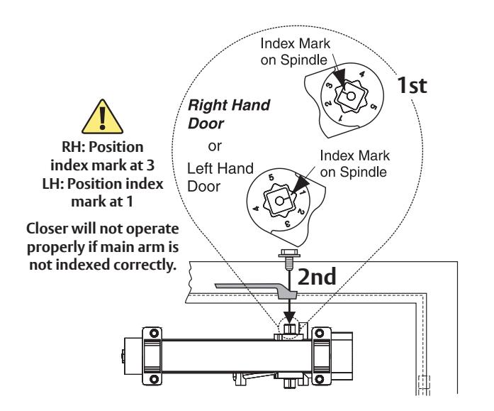
6. Rotate bottom case spindle.

351 Parallel Arm Mount - PH9 Arm Installation continued (Right Hand Shown)

7. Attach Main arm as shown.
8. Open latching speed and closing speed valves.
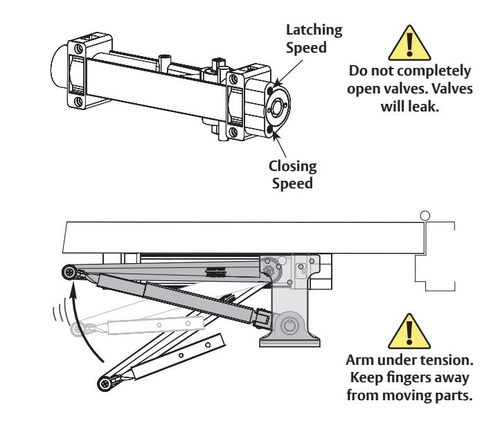
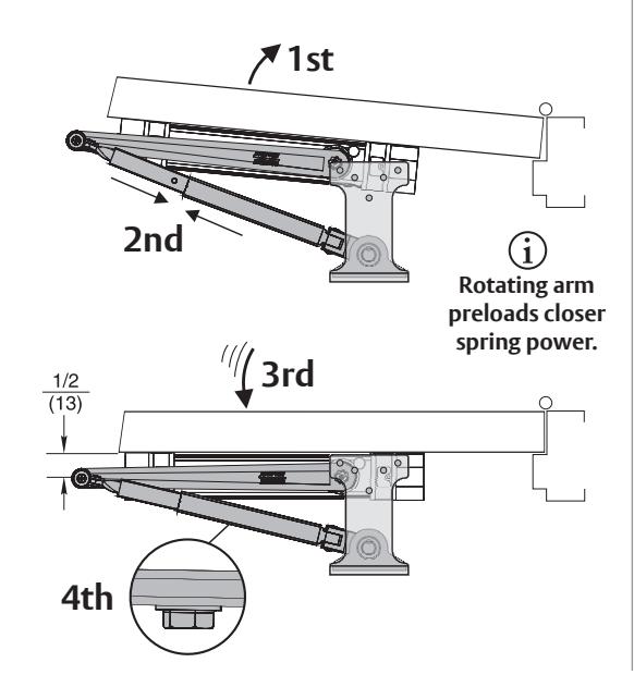
9. Connect arms, preload spring and tighten swivel arm screw.
You've now installed the 351 Hold Open Closer - Parallel Arm Mount. Go to page 7 for closer adjustments and cover installation.
351 Hold Open Closer
SARGENT ASSA ABLOY
Closer Adjustments

Use provided 1/8" hex wrench to turn valves. NEVER force valves out of closer. NEVER completely close backcheck valve. NEVER use backcheck as a door stop.
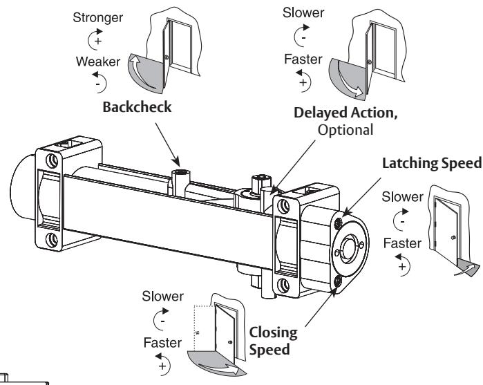

Door must be open to adjust spring closing power. Use 5/8" wrench or socket to turn screw. Refer to chart. Do not use a power drill. Warranty will be void.
Adjust closing time speed between 3 and 6 seconds from 90° to Close. Greater closing times may be required for elderly or handicapped.

If interior doors do not have to comply with ADA requirements, exterior door settings are recommended. Where strong drafts exist, increase spring power as needed by turning spring adjustment screw clockwise. If necessary, reduce spring power by turning screw counter clockwise.
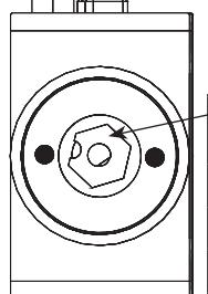
Increase Power
Decrease Power
| 24" Factory Set | nrallel |
|---|---|
| Std/Top Jamb Parallel Std/Top Jamb Pa 24" Factory Set | |
| 30" 2-6 CW 1-5 | : COM |
| 32" 1-4 CW 1-5 CCW | 1-5 CCW |
| 36" 4-7 CW | |
| 40" | Factory Set |
| 42" | 8-11 CW | | ory sec |
| 7-10 CW Factory Set | 1-7 CW |
| 46" 10-12 CW 11-13 CW 1-5 CW | |
| 48" | 10-12 CW | 11-13 CW | 1-3 CW | |
| over 48" up to 18 CW 5 CW & up 8 CV | W & up |
Number of Spring Dower Nut Turns From Eastery Setting
Cover Attachment
cover screws. Place removable insert in unused
cover opening.
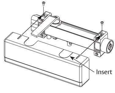
Standard Mount shown Parallel Arm Mount similar
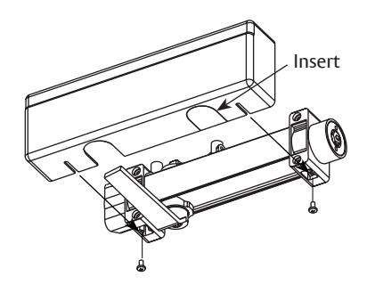
Top Jamb Mount

SARGENT Manufacturing Company 100 Sargent Drive New Haven, CT 06511 USA 800-727-5477
www.sargentlock.com