Installation, Wiring & Programming for 4301 Magnetic Card Reader
Open the original PDF document
View PDFSARGENT ®
4301 Magnetic Card Reader
INSTALLATION, WIRING AND PROGRAMMING
FEATURES:
- LOCK RELEASE RELAY
- LOCK RELEASE TIMER
- FORCED DOOR ALARM RELAY
- PROPPED DOOR ALARM RELAY
- ALARM ZONE SHUNTING RELAY
- TIMED EGRESS INPUT
- 120 USERS
- FRONT PROGRAMMING
- USES ANY ABA STANDARD TRACK II ENCODED MAGNETIC STRIPE CARD
MEMORY
Non-volatile EEPROM memory means your users and instructions will be there whether you remove power for 5 minutes or 5 years.
CARDS/MASTER CODE
The Model 4301 System allows up to 120 individual users to be valid. Any ABA standard Track II encoded magnetic stripe card may be programmed as a user. The Master Code (used to enter the programming mode) is always a code and always user one (1).
FORCED DOOR RELAY
Assisted by the Door position Sensor Loop, this 1 Amp Form-C relay will energize if the door is opened without a valid user entry or egress input. This output can be programmed to energize for up to 15 minutes or latch. It can be reset by a valid code/card entry.
PROPPED DOOR RELAY
Programming a 1 to 15 minute open door time allows the 4301 system to alert you to a propped door by energizing a 1 Amp Form-C relay. Assisted by the Door Position Sensor Loop, this relay will deenergize upon closure of the door.
LOCK RELEASE RELAY
This is an 8 Amp (10 Amp surge) Form-C relay which can be toggled (by code) or timed from 1 to 90 seconds.
ALARM ZONE SHUNT RELAY
Assisted by the Door Position Sensor Loop, this 1 Amp Form-C relay is energized simultaneously with the Lock Release relay providing an easy means of shunting existing door contacts. The relay will continue shunting until the 4301 system sees the door close: preventing nuisance alarms (use the propped door relay instead).
DOOR POSITION SENSOR INPUT
By simply adding a normally closed magnetic door switch, the 4301 system will monitor the position of the door and immediately relock it after valid access has been gained, preventing unwanted "tailgate" entries.
PROGRAMMING
Programming is accomplished by entering instructions at the front of the programming keypad and swiping cards at the reader. Multiple users may be added sequentially at the reader without returning to the keypad. LED guidance makes programming easy and changing cards a matter of seconds for an authorized user.
TIMED EGRESS INPUT
Upon a momentary closure, this normally open loop will trigger the Lock Release relay for the same time period as the Master Code.
KEYPRESS FEEDBACK / AUDIBLE KEYPRESS
The Model 4301 Card Reader System will acknowledge a keypress by momentarily sounding the sounder. This can be turned off through programming.
VESTIBULE/ATM MODE
This mode allows any Track II encoded magnetic stripe card to energize either the Propped Door relay, the Forced Door relay, or both. This function is especially useful when allowing access to a vestibule or automatic teller machine. A new command has been added that will energize the selected relay even if the card is not swiped properly. This is referred to as Vestibule/ATM Mode even on read error (see programming option 12).
SPECIFICATIONS:
ΜΕCΗΔΝΙCΔΙ ·
Case Dimensions: 1.75"w x 4.50"h x 1.55" d
ELECTRICAL
Voltage: 12 to 24 volts AC of DC (selected by jumper) Current: @12VDC 20ma typical - 50 ma worst case @24VDC 25 ma typical - 70 ma worst case Note: Keypads using additional relays require an additional 15ma for each relay energized.
ELECTRICAL:
Output: Main relay: 8 Amp, Form-C @24VDC - 10 Amp surge Alarm Zone Shunting Relay: 1 Amp, Form-C @24VDC Forced Door Relay: 1 Amp, Form-C @24VDC Propped Door Relay: 1 Amp, Form-C @24VDC
ENVIRONMENTAL:
Operating Temperature: -20 degrees F to 130 degrees F (-28 degrees C to 54 degrees C)

System Testing
- 1. Connect the positive (+) lead of your power supply to the terminal strip (TS1) +V input.
- 2. Connect the negative (-) lead of your power supply to the terminal strip (TS1) -V input.
- 3. Turn on your power supply.
- 4. Press 7890#123456*. If all 12 keypresses have been verified, the Card Reader will enter self-test mode. The LED's will flash and the sounder will beep 3 times, then sound continuously for 3 seconds (LED's on swipe will flash). If these responses do not happen, try the test mode again and then call tech support. Note: Self-test mode can be used when troubleshooting a keypad in the field. If you do not get the continuous sound then the memory has been corrupt and should be reprogrammed with the 46 command (see option #16).
- 5. Enter the master code of 1234*. The relay will energize. Refer to programming section to program your system.

System Operation & Notes
Access Control Defaults
The Model 4301 Card Reader System is designed for easy installation in a minimum amount of time. The following defaults have been factory programmed.
| Master Code (user 1) | 1234 * |
|---|---|
| Main Relay will energize for | 5 secs. |
| Keypress Feedback | On |
| Propped door relay will energize after | 30 secs |
| Forced door relay will energize for | 10 secs. |
If defaults must be changed or additional functions are desired, please refer to the PROGRAMMING OPTIONS CHART after you are familiar with the Programming section.
3
Programming Tips
1. Enter programming mode (Note 1) . . . . . Yellow LED Press 99 # (master code) * . . . . . . Flashes slowly 2. To change master code (Note 2) Press 1 # (new master code) * ..... Flashes fast Press (new master code) *..... Flashes slowly If main relay time must be changed, Substitute option 2 from Programming Options chart for step 2 above. 3. To add/change second user Press 2#**......Flashes slowly Swipe card .................................... 4. To Add/change third user Press 3 # * * . . . . . . . . . . . . . . . . Flashes slowly Swipe card ...... Flashes slowly 5. Up to 120 users may be added in this fashion. 6. Exit programming mode
3.1 Programming Notes:
1. The SARGENT Model 4301 System is factory programmed with a master code of 1234 *.
Press * . . . . . Out
- 2. The master code is always user 1.
- 3. The master code allows access to the programming mode and activates the main relay.
- 4. The Master Code must be followed by the *.
- The Master Code may be from 1-6 digits in length, and digits may be repeated.
- If the Master Code is forgotten or does not seem to be working, momentarily push SW1 (see wiring diagram for location) to enter programming mode and go to option #16 and default keypad.
- 7. If the yellow LED lights solid while in programming mode an error has occurred. Press * to clear (yellow LED should flash) and start over from step 2 or 3 above.
- 8. To add multiple users without returning to the keypad, refer to the Programming Options Chart: Option 17.

Programming Option Summary
If the pre-programmed default values must be changed or additional functions are desired, the following options may be programmed.
| ' | |||
|---|---|---|---|
| 1. | Enter programming mode. | Press | 99 # (master code) * |
| 2. |
Change master code/set main relay time (Note 9)
Example: Master code of 4321/relay time of 10 seconds. |
Press
Press |
(time) # 1 # (new code) * (new code)
10 # 1 # 4321 * 4321 * |
| 3. | Add/change user | Press | (user number) # * * (Swipe card) |
| 4. | Add/change user to toggle main relay | Press | (00) # (user number) # * * (Swipe card) |
| 5. | Delete users | Press | (user number) # * * |
| 6. | Turn keypress feedback/audible keypress on | Press | 30 # 0 # 1 # * * |
| 7. | Turn keypress feedback/audible keypress off | Press | 30 # 0 # 0 # * * |
| 8. |
Energize Propped Door relay with any
Track II card (ATM) |
Press | 31 # 0 # 1 # * * |
| 9. | Turn above option (number 8) off | Press | 31 # 0 # 0 # * * |
| 10. |
Energize Forced Door relay with any
Track II card (ATM) |
Press | 31 # 1 # 1 # * * |
| 11. | Turn above option (number 10) off | Press | 31 # 1 # 0 # * * |
| 12. | Energize Vestibule/ATM mode even on read error. | Press | 31 # 2 # 1 # * * |
| 13. | Turn above option (number 12) off | Press | 31 # 2 # 0 # * * |
| 14. | Set propped door time (Note 10) | Press | 44 # (time) # 0 # * * |
| 15. | Set forced door relay time (Note 10) | Press | 45 # (time) # 0 # * * |
| 16. | Erase keypad memory/reset defaults | Press | 46 # 00000 # 00000 # * * |
| 17. | Sequentially add users (Note 11) | Press | 53 # 1 # (starting user number) # * * (swipe first card) (swipe second card) (swipe third card), etc |
4.1 NOTES:
- 1. 2 digits must always represent time. Example: 5 seconds = 05. Latching/toggle is accomplished by entering a time of 00.
- Propped Door and Forced Door times must be programmed in intervals of 10 seconds. I.e. 10, 30, 60...up to 900 seconds. Forced door time of 00 will latch output, until reset by code/card.
- 3. Example: If the starting user number is (2) the first card swiped will be user (2), the next card swiped will be user (3), the next card swiped will be user (4), etc...This option cancels upon any keypress.
Installation of Exterior Card Reader:
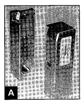
Separate Card Reader Head from Mounting Base with the Allen wrench provided. The Card Reader Head is attached to the Mounting Base by a security hex screw in the bottom of the unit. (View A)
Installation of Card Swipe Mounting Base:
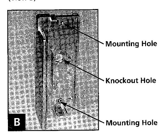
With either a drill bit or punch, remove material in mounting holes and wire knockout location. Hold the Mounting Base up to the mounting surface and mark mounting hole and wire locations.
The Mounting Base comes with two #8 x 1 1/4" (1/8" diam.) Pan Head Screws and wall anchors (if needed).
Attach the Mounting Base with the hardware supplied, if on an exterior surface use the gasket provided. (View B)
Attachment of Control Wires to Card Reader Head:
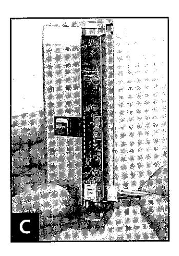
The 4 Wire Harness (Black, Red, White/Black, and White/Yellow) is keyed, and can only go on one way. For reference, the Black wire is nearest the top of the Control Head. (View C)
Location of Card Reader Control Module: Should be located on inside (non-secure) side of building. Unit can be located on wall opposite reader or in an access cabinet. It should be located within 30 feet from Reader Head for ease of programming cards.
The maximum allowable distances between the Reader Head and the Card Reader Control Module are as follows:
- 1000ft 18AWG
- 500ft 20AWG
- 250ft 22AWG (Min. wire size allowed)
Removal of Circuit Board from Interior Key Pad:
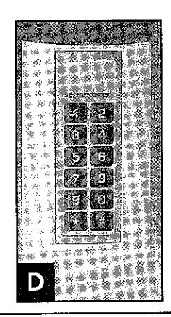
- 1. Orientate Keypad Unit as shown. (View D)
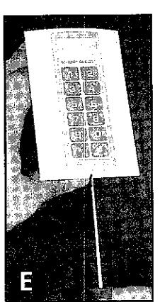
- 2. Using a flat head screwdriver, insert into slot on the bottom of Keypad. This will release the Keypad from the Base. (View E)
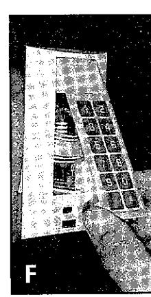
- 3. Gently pull the Keypad from the base, being careful not to pull against the ribbon cable. (View F)
Wiring of Internal Keypad Circuit Board:
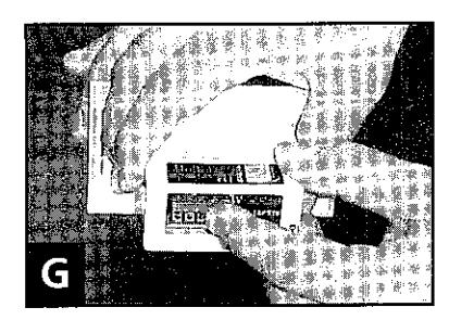
1. With the Keypad removed from the Base, gently push the circuit board from the rear of the base. This will bring the internal assembly out through the front of the Base. (View G)
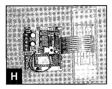
2. With the internal Circuit Board removed from the base, orientate as shown. (View H)
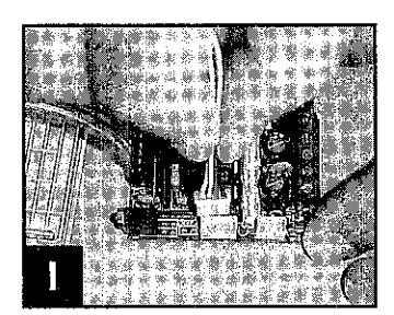
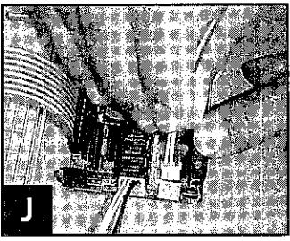
3. Install the appropriate control wiring as shown. Refer to the wiring instructions within this manual for proper connections. The connectors are keyed and can only go on one way. (View I and J)
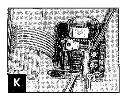
4. The accessory wiring will be installed per the wiring instructions within this manual. The connectors are keyed and can only go on one way. (View K)
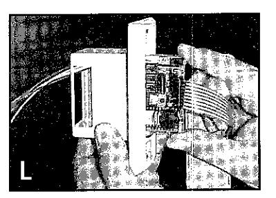
Once appropriate wiring is connected, fold the ribbon cable over the circuit board and insert the Circuit Board back into the Keypad base as shown. The control wiring is orientated to the top of the Base. (View L)
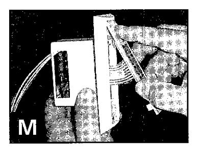
6. With the Circuit Board seated within the Keypad base, insert the tabs on top of the Keypad into the slots on the base. From the bottom of the Keypad, snap the assembly onto the Base. (View M)
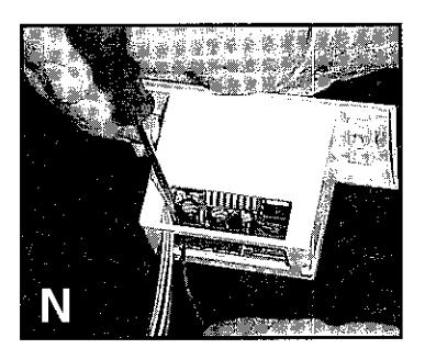
Now that the Circuit Board is reseated, attach the power wires and lock control wires per the wiring instructions within this manual. (View N)
8. Insert Keypad into electrical wall box.
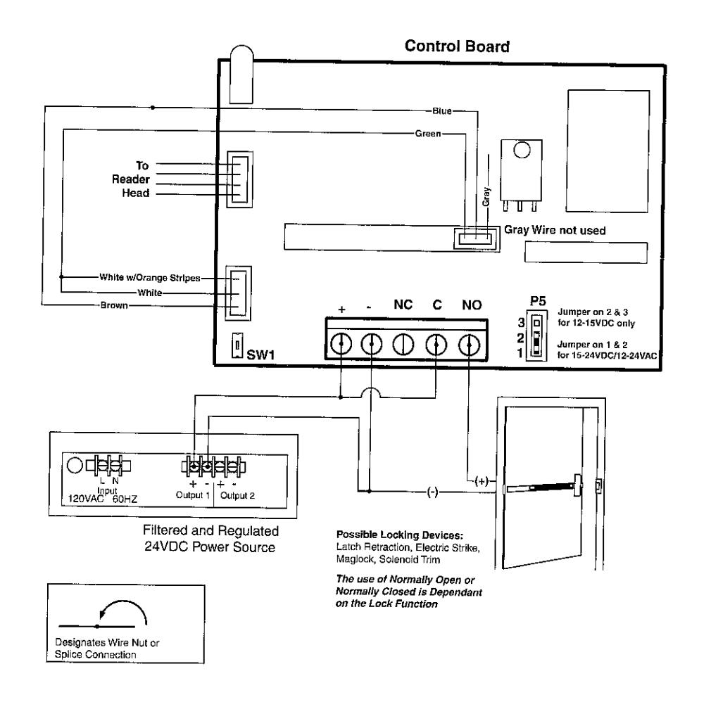
System Wiring for Power, Card Reader and Main Control Board
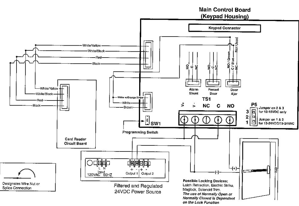
Technical Notes
- For 12-15 VDC the P5 jumper MUST be on pins 2 & 3. For 12-24VAC or 16-24VDC the P5 jumper MUST be on pins 1 & 2.
- To avoid ESD (electro-static discharge) from interfering with the operation of the SARGENT system, ground the negative terminal of the keypad to earth ground. If the power supply can not be grounded, then the case should be grounded.
- When using this device to operate an electric locking device you must install either the diode for DC voltage or the MOV for AC voltage (as shown in diagrams). They should be installed as close to the lock as possible. Installation of these devices will prevent the "electrical kick back" voltage generated by the locking device from damaging the keypad.
- If you are using AC voltage to power your SARGENT system you must install the MOV and appropriate resistor across your input voltage. Installation of these devices will help filter any "surges" or "transients" from the AC voltage source (as shown in diagrams) which could damage the keypad.
- The bi-color LED provided with this SARGENT system will illuminate red when the Lock Release Relay is off, and green when the relay is energized.
- If a door position sensor input is not used, it must be jumpered closed.
Main Control Board Sargent3287 Door Status (Keypad Housing) 0 Keypad Connector 0 White/Orange TS1 NC: C NO Jumper on 2 & 3 for 12-15VDC only S <u>W1</u> Jumper on 1 & 2 for 15-24VDC/12-24VAC Programing Switch Install MOV & Resisto With AC Voltage Install IN4004 Diode for DC Voltage Install MOV for AC Voltage Hesistor 100hm ≅ 12 VAC 100ohm @ 24 VAC Designates Wire Nut or Splice Connection Sargent 1584 Maglock 120VAC 60HZ Oulput 1 Output 2 Filtered and Regulated 24VDC Power Source Note: Locking Device shown is a Maglock, it could be a Electric Strike, Solenoid Operate Lock, Latch Retraction or other type of Electromechanical Lock. The use of Normally Open or on the Lock Function
System Wiring Shown For Maglock (See Note)
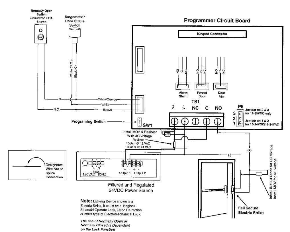
Technical Notes
- For 12-15VDC the P5 jumper MUST be on pins 2 & 3. For 12-24VAC or 16-24VDC the P5 jumper MUST be on pins 1 & 2.
- To avoid ESD (electro-static discharge) from interfering with the operation of the SARGENT system, ground the negative terminal of the keypad to earth ground. If the power supply can not be grounded, then the case should be grounded.
- When using this device to operate an electric locking device you must install either the diode for DC voltage or the MOV for AC voltage (as shown in diagrams). They should be installed as close to the lock as possible. Installation of these devices will prevent the "electrical kick back" voltage generated by the locking device from damaging the keypad.
- If you are using AC voltage to power your SARGENT system you must install the MOV and appropriate resistor across your input voltage. Installation of these devices will help filter any "surges" or "transients" from the AC voltage source (as shown in diagrams) which could damage the keypad.
- The bi-color LED provided with this SARGENT system will illuminate red when the Lock Release Relay is off, and green when the relay is energized.
- If a door position sensor input is not used, it must be jumpered closed.