Installation Guide HS4 Controller installation_guide_cu4eb8_225205.1
Open the original PDF document
View PDFXS4 Controller

CU4EB8
Installation guide Eng
E Guía de instalación
Guide d'installation F
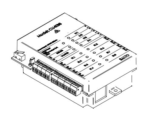
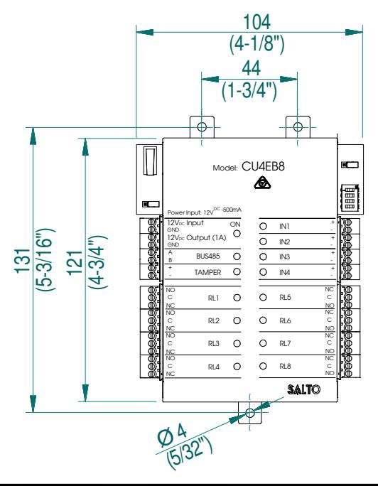
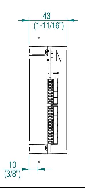
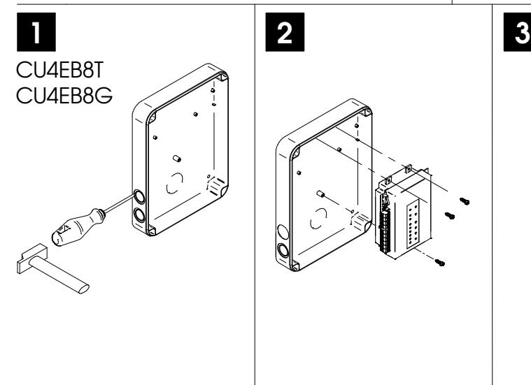
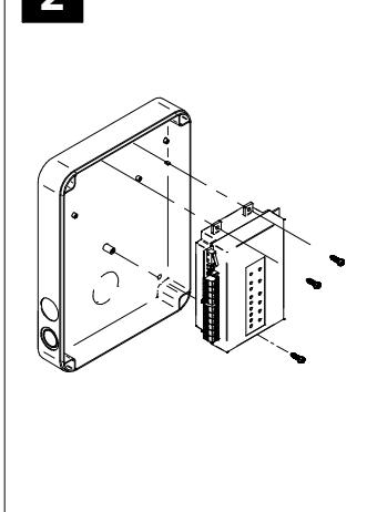
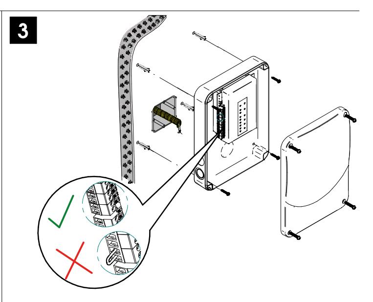
Mechanical Installation Eng E Instalación mecánica Installation mécaniqu F e
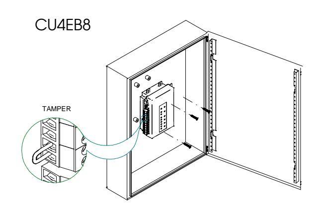
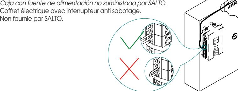
Electric box with tamper switch. Electric box not supplied by SALTO. Eng
Caja eléctrica con detector de intrusión o tamper. Caja con fuente de alimentación no suministada por SALTO. E
Coffret électrique avec interrupteur anti sabotage. F
CU4EB8
XS4 Controller

-
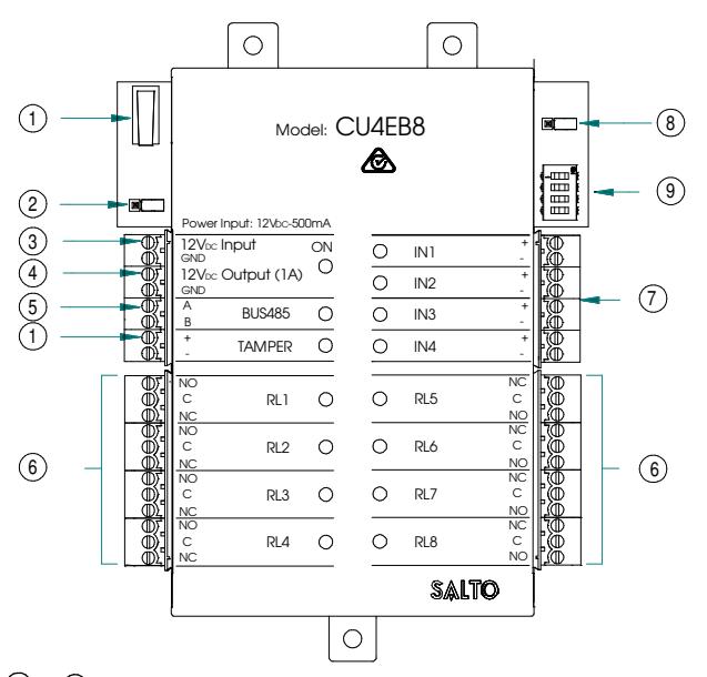
El pulsador del Tamper, está conectado en paralelo con la entrada de tamper. 1
E
- Resistor del terminal BUS RS485 tiene que estar en la posición ON cuando la CU4EB8 esté al final del BUS. 2
- Entrada de alimentación.
- Salida alimentada: esta salida se conecta directamente a la entrada de alimentación protegida por un fusible de 1A. BUS485. 4
- Conexiones relés: tener en cuenta las restricciones de carga (2A-30VDC). Utilice el varistor suministrado si la carga es de tipo inductivo. 6
- Entradas: el instalador ha de identificar el cable para el puente dependiendo de la configuración de la entrada. 7
- Jumper Online/Offline: configure la unidad para trabajar en modo offline. 8
- Dip switch: 9
Modo offline-> Diríjase a la tabla de salidas para asignar el número de salida al relé.
-
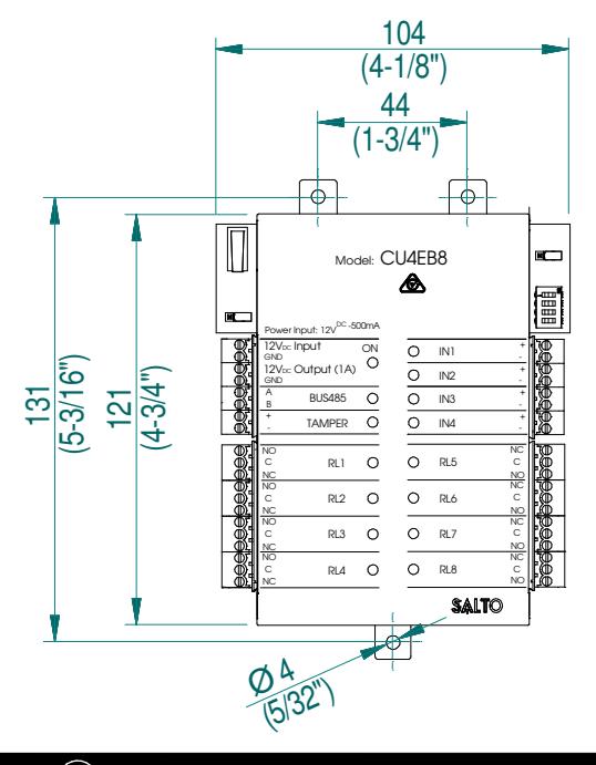
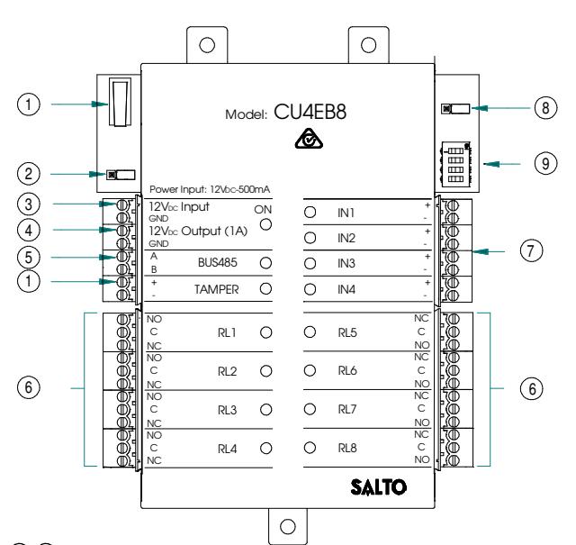
Tamper switch is connected in paralell with tamper input. 1
Eng
- BUS RS485 Terminal Resistor must be in the ON position when the CU is connected at the end of the BUS. 2
- Power Input. 3
- Power Output: This output is directly connected to the power Input port protected by a 1A fuse. 4
- BUS485. 5
- Relay Connections: Please take into account the max. load restrictions(2A-30VDC). Use the provided varistor if an inductive load is used. 6
- Inputs: Installer must identify the bridge cable needed depending on the input configuration. 7
- Online/Offline jumper:Configure the unit to work as an offline device. Dip switch: 8
- Offline Mode->See output table to assign the output number to a relay. 9
-
Contacteur anti sabotage monté en parallèle avec l'entrée anti sabotage. 1
F
- La résistance de fin de bus RS485 est nécessaire (position ON) lorsque la CU est positionnée à l'extrémité du bus. 2
- Entrée Alimentation. 3
- Sortie Alimentation:Cette sortie est reliée directement au port d'entrée de l'alimentation protégée par un fusible de 1A. 4
- BUS485. 5
- Connexion des relais:S'il vous plaît prendre en compte les restrictions de charge max. (2A-30VDC). Utilisez les varistances fournis si une charge inductive est utilisée. 6
- Entrées:L'installateur doit identifier le câble nécessaire en fonction de la configuration d'entrée. 7
- Cavalier Online/Offline:Indique si l'unité fonctionne en tant qu'équipement Offline. 8
- Dipswitch: 9
Mode Offline->Voir la table des sorties pour assigner aux relais leur numéro de sortie.
| Factory configuration (offline mode) | |||
|---|---|---|---|
| IN1 | Disable | ||
| IN2 | Disable | ||
| IN3 | Disable | ||
| IN4 | Disable | ||
| RL1 | Output number 1 | ||
| RL2 | Output number 2 | ||
| RL3 | Output number 3 | ||
| RL4 | Output number 4 | ||
| RL5 | Output number 5 | ||
| RL6 | Output number 6 | ||
| RL7 | Output number 7 | ||
| RL8 | Output number 8 | ||
| Configuración de fábrica (modo Offline) | ||||
|---|---|---|---|---|
| IN1 | Deshabilitada | |||
| IN2 | Deshabilitada | |||
| IN3 | Deshabilitada | |||
| IN4 | Deshabilitada | |||
| RL1 | Salida número 1 | |||
| RL2 | Salida número 2 | |||
| RL3 | Salida número 3 | |||
| RL4 | Salida número 4 | |||
| RL5 | Salida número 5 | |||
| RL6 | Salida número 6 | |||
| RL7 | Salida número 7 | |||
| RL8 | Salida número 8 | |||
| Configuration d'usine (Mode Offline) | ||||
|---|---|---|---|---|
| IN1 | Désactivé | |||
| IN2 | Désactivé | |||
| IN3 | Désactivé | |||
| IN4 | Désactivé | |||
| RL1 | Sortie numéro 1 | |||
| RL2 | Sortie numéro 2 | |||
| RL3 | Sortie numéro 3 | |||
| RL4 | Sortie numéro 4 | |||
| RL5 | Sortie numéro 5 | |||
| RL6 | Sortie numéro 6 | |||
| RL7 | Sortie numéro 7 | |||
| RL8 | Sortie numéro 8 | |||
Eng Electrical characteristics:
Operation conditions
| Min | Typ | Max | Unit | |
|---|---|---|---|---|
| Temperature | 0 | 25 | 60 | ºC |
| Humidity | 35 | 85 |
Power
| Min | Nom. | Max | Unit | |
|---|---|---|---|---|
| InputVoltage | 12 | V | ||
| Current | 1500 Note1 | mA | ||
| consumption | ||||
| Outputport | 1 | A | ||
| current Note2 |
Input
| Electrical | 5v Note3 |
|---|---|
| characteristics | |
| Configuration | ViaSoftware Note4 |
Cable recommendation
| BUS485 | Twisted pair AWG24 |
|---|---|
| Inputs | AWG24 |
Outputrelays
| Ratedload(resistive) | 2A-30Vdc |
Note 1:This is the maximum consumption of the CU4EB8 using the output power port (1A max). If the power output port is not used, the maximum consumption is 500mA Note 2:Same voltage as the input.
Note 3:1K pull-up resistor.
Note 4:See the software User Manual.
XS4 Controller

© Características Flectricas:
Condiciones ambientales
| Min | Тур | Max | Unit | |
|---|---|---|---|---|
| Temperatura | 0 | 25 | 60 | ōC |
| Humedad | 35 | 85 |
Potencia
| Min | Nom. | Max | Unit | |
|---|---|---|---|---|
| Voltage | 12 | V | ||
| Consumo de | 1500 Nota 1 | mA | ||
| la corriente | ||||
|
Salida
Corriente Nota 2 |
1 | Α |
Entrada
| Características | 5ν Nota 3 |
| Electricas | |
| Configuración | Via Software Nota 4 |
Cable recomendado
| BUS485 | AWG24 par trenzado |
| Inputs | AWG24 |
Relés de salida
| 2A-30Vdc |
|---|
Nota 1:Este es el consumo máximo de la CU4EB8 utilizando el conector de salida (1A máx). Si el conector de salida no se usa, el consumo máximo es de 500mA.
Nota 2:Misma tensión que en la entrada. Nota 3:Resistencia de 1K.
Nota 4:Ver manual de usuario del software.
(F) Caractéristique électrique:
Condition de fonctionnement
| Min | Тур | Max | Unité | |
|---|---|---|---|---|
| Température | 0 | 25 | 60 | ōС |
| Humidité | 35 | 85 |
Puissance
| 1 413541166 | ||||
|---|---|---|---|---|
| Min | Nom. | Max | Unité | |
| Tension d'entrée | 12 | V | ||
| Courant | 1500 Note 1 | mA | ||
| de consommation | 1 | |||
| Courant en sortie | 1 | Α | ||
| du bornier Note 2 |
Entrée
| Caractéristique | 5V Note3 |
|---|---|
|
électrique
Configuration |
ViaSoftware Note 4 |
Type de câble
| Bus d'extension | Paire torsadée AWG24 |
| Entrée | AWG24 |
0
OFFLINE
Relais de sortie
| Charge nominal | (résistive) | 2A - 30Vdc |
|---|---|---|
Note 1: Ceci est la consommation maximale de la CU4EB8 lorsque le bornier de sortie alimentation (1A max) est utilisé. Si le bornier de sortie alimentation n'est pas utilisé, la consommation maximum est 500mA. Note 2: Memem tension que l'entrée. Note 3: Résistance de pull-up 1K. Note 4: Consultez le manuel du logiciel utilisateur.
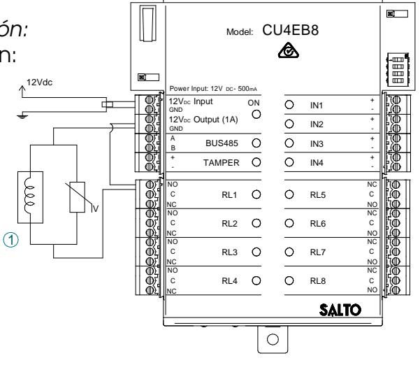
installation example:
- E Ejemplo de instalación:
- (F) Exemple d'installation:
0
- 1) Electric Strike
- (1) Cerradero eléctrico
- (1) Gâche électrique
Offline configuration
- (1) The unit must be connected to a CU4200 in stand alone mode (dip-switch in the CU4200 -> 0000).
- 2 In offline mode, the inputs are disabled.
- 3 The dip-switch configures the number of the output in the different relays as the following
- 4 To assign the output number to a specific user see SALTO ProAccess SPACE User Manual.
- © Configuración offline
- La unidad debe ser conectada a una CU4200 en modo autónomo (dip-switch en CU4200 -> 0000).
- (2) En modo offline, las entradas están deshabilitadas.
- 3 Los dip-switch se utilizan para configurar el número de la salida en los diferentes relés según la tabla siauiente.
- Ú Diríjase al manual de usario de SALTO ProAccess SPACE para asignar el número de salida a un usuario específico.
(F) Configuration Offline
- ① L'appareil doit être connecté à une CU4200 en mode autonome (dip-switch du CU4200 -> 0000).
- (2) En mode offline, les entrées sont désactivées.
- ③ Le dip-switch configure le numéro de sortie des différents relais en fonction du tableau suivant.
- (4) Pour attribuer un numéro de sortie à un usager particulier voir le Manuel d'utilisation de SALTO ProAccess SPACE.

XS4 Controller

TABLE 1/ TABLA 1/ TABLEAU 1
| RL1 | RL2 | RL3 | RL4 | RL5 | RL6 | RL7 | RL8 | RL1 | RL2 | RL3 | RL4 | RL5 | RL6 | RL7 | RL8 | RL1 | RL2 | RL3 | RL4 | RL5 | RL6 | RL7 | RL8 | |||
|---|---|---|---|---|---|---|---|---|---|---|---|---|---|---|---|---|---|---|---|---|---|---|---|---|---|---|
| 0000 | 1 | 2 | 3 | 4 | 5 | 6 | 7 | 8 | 0110 | 49 | 50 | 51 | 52 | 53 | 54 | 55 | 56 | 1100 | 97 | 98 | 99 | 100 | 101 | 102 | 103 | 104 |
| 0001 | 9 | 10 | 11 | 12 | 13 | 14 | 15 | 16 | 0111 | 57 | 58 | 59 | 60 | 61 | 62 | 63 | 64 | 1101 | 105 | 106 | 107 | 108 | 109 | 110 | 111 | 112 |
| 0010 | 17 | 18 | 19 | 20 | 21 | 22 | 23 | 24 | 1000 | 65 | 66 | 67 | 68 | 69 | 70 | 71 | 72 | 1110 | 113 | 114 | 115 | 116 | 117 | 118 | 119 | 120 |
| 0011 | 25 | 26 | 27 | 28 | 29 | 30 | 31 | 32 | 1001 | 73 | 74 | 75 | 76 | 77 | 78 | 79 | 80 | 1111 | 121 | 122 | 123 | 124 | 125 | 126 | 127 | 128 |
| 0100 | 33 | 34 | 35 | 36 | 37 | 38 | 39 | 40 | 1010 | 81 | 82 | 83 | 84 | 85 | 86 | 87 | 88 | |||||||||
| 0101 | 41 | 42 | 43 | 44 | 45 | 46 | 47 | 48 | 1011 | 89 | 90 | 91 | 92 | 93 | 94 | 95 | 96 |
ONLINE
Eng Online Configuration:
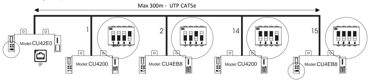
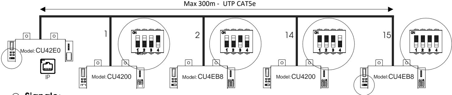
- Connect all the devices through the BUS485and power the CU4EB8. 1
-
Create and set up the CU4EB8 on the Software (Consult the SALTO ProAccess SPACE user manual). 2
- Asign the CU4EB8 to the node it is connected.
- Define the address in the BUS485.
- OFFLINE - The relay out set up has to be done through the SALTO ProAccess SPACE software.
-
Put the Resistor in ONLINE mode. 3
- The CU4EB8 dip-switch setting is used to give each device on the BUS485 a unique address.
- Ensure that the address in the software is the same as the one you put on the hardware. (See Table 2).
- Both ends of the BUS485 must have the RS485BUS termination resistor in the ON position, intermediate devices need to have the resistor in OFF position.
Supervised input connections:
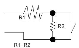
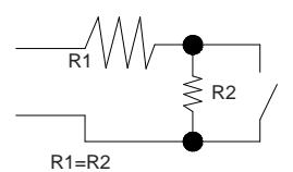
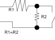
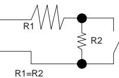
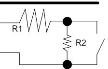
R2 R1 R1=R2 By default all inputs are disabled. They can be configured through the software. If the inputs are supervised, the resistance value R1 and R2 are defined in the software:1k (recommended), 1k5,2k2,3k3,4k7,6k8,10k.
Configuración online: E
- Hacer todas las conexiones físicas de la red (BUS485) y alimentar la CU4EB8. 1
-
Dar de alta la CU4EB8 en el Software (consultar el manual de usuario de SALTO ProAccess SPACE). 2
- Asignar el nodo al que se va a conectar.
- Definir la dirección en el BUS485.
- La configuración de las salidas de los relés ha de hacerse a través del software SALTO ProAccess SPACE.
-
Poner el jumper en modo ONLINE. 3
- El dip-switch de la CU4EB8 se usa para asignarle una dirección dentro del BUS485.
- Esta dirección ha de ser la misma que la asignada en el software. Ver tabla 2.
- Ambos extremos del BUS485 han de tener la resistencia del terminal en posición On, y el resto de CU4EB8 han de tener esta resistencia en posición OFF.
TABLE 2/ TABLA 2/ TABLEAU 2
| ADDRESS | ADDRESS | ADDRESS | |||
|---|---|---|---|---|---|
| 0001 | Address 1 | 0111 | Address 7 | 1101 | Address 13 |
| 0010 | Address 2 | 1000 | Address 8 | 1110 | Address 14 |
| 0011 | Address 3 | 1001 | Address 9 | 1111 | Address 15 |
| 0100 | Address 4 | 1010 | Address 10 | ||
| 0101 | Address 5 | 1011 | Address 11 | ||
| 0110 | Address 6 | 1100 | Address 12 |
Conexión de entradas supervisadas
Por defecto, las entradas están deshabilitadas. Pueden configurarse a través del software. Si las entradas están supervisadas el valor de resistencia R1 y R2 se define en el Software: 1k (recomendado), 1k5,2k2,3k3,4k7,6k8,10k.
XS4 Controller

Configuration online: F F
- Connectez les équipementssur le bus RS485 et mettez sous tension la CU4EB8. 1
-
Créez et parametrez la CU4EB8 dans le logiciel (voir le manuel du logiciel SALTO Pro Access SPACE). 2
- Assignez le nœud auquel est connectée la CU4EB8.
- Définissez l'adresse dans le bus RS485.
- La configuration des sorties relais doit être faite à travers le logiciel SALTO Pro Access SPACE.
-
Mettez la résistance en mode Online. 3
- Les micro-interrupteurs servent à donner à la CU4EB8 une adresse unique sur le bus RS485.
- Assurez-vous que l'adresse définie dans le logiciel est la même que celle sur le matériel (vois table).
- Chaque extrémité du bus RS485 doit avoir la résistance de terminaison sur la position ON, les équipements intermédiaires doivent avoir la résistance sur la position OFF.

Same configuration at SALTOs ProAccess SPACE Software
Connexion d'entrée supervisée.
Par défaut, toutes les entrées sont désactivées. Elles peuvent être configurées avec le logiciel.
Si les entrées sont supervisées, la valeur des résistances R1 et R2 sont définies dans le logiciel : 1k (recommandé), 1k5, 2k2, 3k3, 4k7, 6k8, 10k.

OFFLINE ONLINE
Exemple de configuration: F
Même configuration que le logiciel SALTO ProAccess SPACE
Ejemplo de configuración: E
Misma configuración que en el Software ProAccess SPACE de SALTO
Signaling: Eng
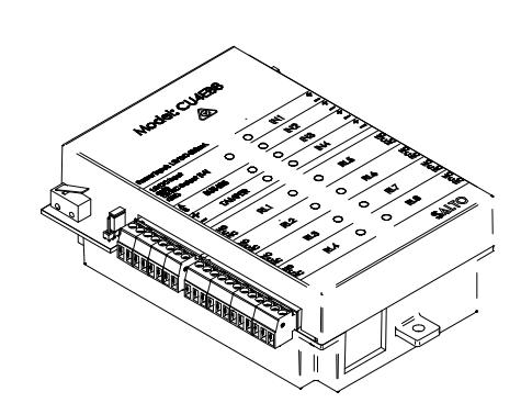
The LEDs in the top layer of the CU4EB8 show the state of the system:
| LED name | Description |
| GREEN ON: the unit is powered correctly | |
| ON | BLINKING RED: the unit is not powered properly (check power supply) |
| OFF: not powered | |
| TAMPER | ON: tamper alarm active |
| OFF: tamper alarm not active | |
| IN1-IN4 | ON: active input (depends on the input type configured in the software) |
| OFF: inactive input (depends on the input type configured in the software) | |
| RL1-RL8 | ON: the relay is activated (NO is connected with C). |
| OFF: the relay is inactive (NC is connected with C). |
Señalización: E
Los LEDs en la parte superior de la CU4EB8 mostran el estado del sistema:
| Nombre del LED | Descripción |
|---|---|
| VERDE ON: el dispositivo está correctamente alimentado | |
| ON | ROJO INTERMITENTE: el dispositivo no está correctamente alimentada (comprobar la fuente de alimentación) |
| OFF: sin alimentación | |
| TAMPER | ON: alarma tamper activada |
| OFF: alarma tamper desactivada | |
| IN1-IN4 | ON: input activado (depende del tipo de input configurado a través del software) |
| OFF: input desactivado (depende del tipo de input configurado a través del software) | |
| RL1-RL8 | ON: relé activado (NO está conectado con C). |
| OFF: relé desactivado (NC está conectado con C). |
Signalisation: F
Les LEDS en façade avant de la CU4EB8 indique l'état du système:
| Nom LED | Description |
|---|---|
| VERT : l'appareil est correctement alimenté | |
| ON | Rouge clignotant : l'appareil est mal alimenté (vérifier la tension d'alimentation) |
| OFF: non alimenté | |
| TAMPER | ON : alarme active |
| OFF : alarme désactivé | |
| IN1-IN4 | ON : entrée active (dépend du type d'entrée configuré dans le logiciel) |
| OFF : entrée inactive (dépend du type d'entrée configuré dans le logiciel) | |
| RL1-RL8 | ON : le relais est actif (NO est connecté avec C) |
| OFF : le relais est inactif (NC est relié à C) |

XS4 Controller

CU4EB8
Installationsanleitung D
Installatiehandleiding NL
Installationsguide SVE

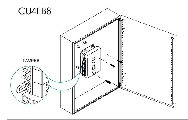
Box mit Sabotagekontakt. D
Die Spannungsversorgung wird nicht von SALTO bereitgestellt.
Bij een behuizing met sabotage schakelaar dient deze aangesloten te worden. NL
Stroonvoorziening niet mee gelever door SALTO. Strömförsörjning medföljer ej. SVE

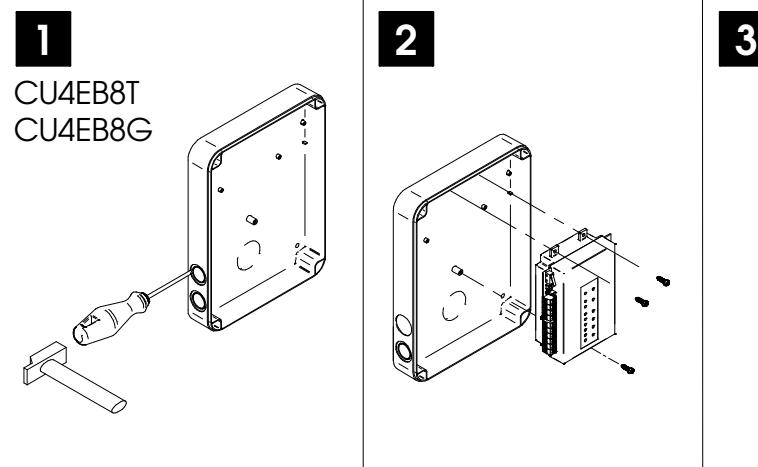
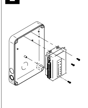
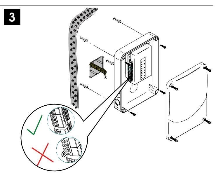
XS4 Controller

-
Der Sabotageschalter ist parallel mit dem Sabotage Eingang (Tamper) geschaltet.
- (2) 485 Bus Abschluss Wiederstände notwendig (ON Position) wenn die CU am Anfana oder Ende des Buses sitzt.
- (3) Spannungseingang.
- 4 Spannunsausgang: Dieser Spannungsausgang ist direkt mit dem Spannungseingang verbunden, jedoch durch eine 1A Sicherung abgesichert.
- (5) BUS485.
- 6 Ausgangsrelais: Bitte beachten Sie die maximale Schaltleistung von 2A-30VDC. Nutzen Sie die beiliegenden Varisatoren, für Induktive Verbraucher.
- (7) Eingänge : Bei der Installation müssen je nach Konfiguration eventuell Eingänge gebrückt werden.
- (8) Online/Offline jumper: Das Gerät muss für Offline konfiguriert werden um als Offlinegerät zu funktionieren.
- (9) Dip Schalter: Offline Modus-> Siehe Ausgangstabelle um die Ausgangsnum-mer einem Relais zuzuordnen.
-
(III) Sabotageschakelaar is parallel aangesloten op sabotage ingang.
(2) RS485 Bus eindweerstand moet in de stand ON staan wanneer de
- CU is aangesloten op het einde van de buslijn. ③ Voeding ingang .
- 4 Voeding uitgang: Deze uitgang is direct aangesloten op de voeding ingang, deze is beveiligd met een 1A zekering.
- (5) RS485 BUS
- Relais Uitgangen: Houd rekening met de max. belasting van (2A-30VDC). Gebruik de meegeleverde varistor als er eeninductieve belasting wordt gebruikt.
- (7) Ingangen: Het is benodigd een kabelbrug (lus) plaatsen afhankelijk van de configuratie van de ingangen.
- (8) Online / jumper: Configureer van de CU4EB8 om te werken als een offline apparaat.
- 9 Dip switch:
Offline Mode-> Zie overzichtstabel voor het correcte uitgangsnummer, om deze toe te wijzen aan een relais.
| (SVE) (1) | Sabotagegivare | är kopplad parrallellt med sabotageingång. |
|---|---|---|
| DIIGO DO 405 E |
- 2 BUSS RS485 Termineringen måste vara i läge TILL när enheten är den sista anslutningskedjan.
- 3 Strömingång.
- Strömutgång: Denna utgång är direkt ansluten till strömingån-gen och skyddas av en 1A säkring.
- (5) BUSS485.
- Relä Anslutningar Vänligen ta hänsyn till att max 2A 30VDC kan användas. Använd den medföljande varistor om en induktiv belastnina används.
- Ingångar: Installatören måste identifiera vilka byglingar som behövs beroende på konfigurationen.
- ® Online / Offline jumper: Konfigurera enheten att fungera som en offline -enhet.
- 9 Dip switch:
tabell för att tilldela nummer till ett relä .
| Werkskonfi | Werkskonfiguration (Offline Modus) | |||||
|---|---|---|---|---|---|---|
| IN1 | Deaktiviert | |||||
| IN2 | Deaktiviert | |||||
| IN3 | Deaktiviert | |||||
| IN4 | Deaktiviert | |||||
| RL1 | Ausgang Nr. 1 | |||||
| RL2 | Ausgang Nr. 2 | |||||
| RL3 | Ausgang Nr. 3 | |||||
| RL4 | Ausgang Nr. 4 | |||||
| RL5 | Ausgang Nr. 5 | |||||
| RL6 | Ausgang Nr. 6 | |||||
| RL7 | Ausgang Nr. 7 | |||||
| RL8 | Ausgang Nr. 8 | |||||
| Fabrieks co | Fabrieks configuratie (offline-modus) | ||||
|---|---|---|---|---|---|
| IN1 | Uitgeschakeld | ||||
| IN2 | Uitgeschakeld | ||||
| IN3 | Uitgeschakeld | ||||
| IN4 | Uitgeschakeld | ||||
| RL1 | Uitgang nummer 1 | ||||
| RL2 | Uitgang nummer 2 | ||||
| RL3 | Uitgang nummer 3 | ||||
| RL4 | Uitgang nummer 4 | ||||
| RL5 | Uitgang nummer 5 | ||||
| RL6 | Uitgang nummer 6 | ||||
| RL7 | Uitgang nummer 7 | ||||
| RL8 | Uitgang nummer 8 | ||||
| Fabriksinställning ( offlineläge ) | ||||||
|---|---|---|---|---|---|---|
| IN1 | Avaktiverad | |||||
| IN2 | Avaktiverad | |||||
| IN3 | Avaktiverad | |||||
| IN4 | Avaktiverad | |||||
| RL1 | Utgång 1 | |||||
| RL2 | Utgång 2 | |||||
| RL3 | Utgång 3 | |||||
| RL4 | Utgång 4 | |||||
| RL5 | Utgång 5 | |||||
| RL6 | Utgång 6 | |||||
| RL7 | Utgång 7 | |||||
| RL8 | Utgång 8 | |||||
D Elektronische Charakteristik:
Umgebungsbedingungen
| Min | Тур | Max | Einheit | |
|---|---|---|---|---|
| Temperatur | 0 | 25 | 60 | ōС |
| Feuchtigkeit | 35 | 85 |
Spannung
| Spannang | ||||
|---|---|---|---|---|
| N | 1in | Nom. | Max | Einheit |
| Eingangsspannung | 12 | V | ||
| Stromverbrauch | 1500 Note1 | mA | ||
| Steuerung | ||||
| Max. Belastung | 1 | Α | ||
| Spannungsausgang i | Note 2 |
Eingang
| Max. Spannung | 5V Note3 |
|---|---|
| Konfiguration | ViaSoftware Note 4 |
Verkabelung
| Erweiterungs Bus | Twisted pair AWG24 |
|---|---|
| Inputs | AWG24 |
Ausgangsrelais
| Zulässige Belastung | 2A-30Vdc |
|---|
Note 1: Die angegebene Stromaufnahme bezieht sich auf das CU4EB8 (1A max). Wenn der Spannungsausgangsanschluss nicht genutzt wird, liegt die maximale Stromaufnahme bei 500mA. Note 3:1K Pull-Up-Wiederstand.
Note 4:Bitte im Softwarehandbuch nachschlagen.
XS4 Controller

® Elektrische eigenschappen
Omgeving
| Temperatuur | 0 | 25 | 60 | C | |
| ı | Vochtigheid | 35 | 85 |
Vermogen
| Min | Nom. | Max | Eenheid | |
|---|---|---|---|---|
| Input Voltage | 12 | V | ||
| Stroomverbruik | 1500 Punt 1 | mA | ||
|
Stroom
uitgaand Punt 2 |
1 | А |
Ingang
|
Elektrische
eigenschappen |
5 V Punt 3 |
|---|---|
| Configuratie | ViaSoftware Punt 4 |
Kabel aanbeveling
| Uitbreidin gsbus | Twisted pair AWG24 |
|---|---|
| Inputs | AWG24 |
Relaisuitgangen
Nominale belasting (resistief)2A-30Vdc
Punt 1:Het maximale verbruik van de CU4EB8 is (1A max) op de uitgangspoort. Als deze poort niet wordt gebruikt, is het maximale verbruik 500mA.
Punt 2:Dezelfde spanning als de ingang.
Punt 3:1K weerstand.
Punt 4:Zie de Software gebruikershandleiding.
(SVE) Tekniska data:
Arbetsområde
| Temperatur | 0 | 25 | 60 | ōC |
| Fukt | 35 | 85 |
Ström
| Min | Nom. | Max | Enhet | |
|---|---|---|---|---|
| Spänning in | 12 | V | ||
|
Strömför
-brukning |
1500 Not 1 | mA | ||
| Spänning | 1 | Α | ||
| ut | Not 2 |
Drift
| Spänning | 5V Not 3 |
|---|---|
| Konfiguration | Via Mjukvara Not4 |
Kabelrekommendationer
| Expansionsbuss | Twisted pair AWG24 |
|---|---|
| Ingångar | AWG24 |
Reläutgångar
| Märkström (resistiv) 2 | A-30Vdc |
|---|
Note 1:Detta är den maximala förbrukningen av CU4EB8 om strömutgången används till max (1A max) . Om strömutgången inte används, är den maximala förbrukningen 500mA .
Note 2:Samma spänning som ingången.
Note 3:1K "pull-up" motstånd.
Note 4:Se mjukvarans bruksanvisning.
① Installationsbeispiel:
- Mulinitaliatievoorbeeld:
- (v) Installationsexempel:
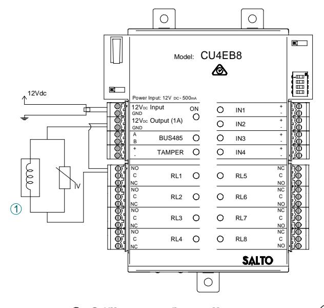
- (1) Türöffner
- NL) (1) Elektrische sluitplaat
- (SVE) (
- (1) Elslutbleck
(D) Offline Konfiguration:
(1) Das Gerät muss mit einer CU4200 im Stand-Alone Modus (Dip-Schalter auf der CU4200 -> 0000) verbunden sein.
2 Im Offline-Modus sind die Eingänge deaktiviert.
- ③ Der DIP-Schalter konfiguriert die Nummer des Ausgangs in den verschiedenen Relais, wie die folgende Tabelle beschrieben.
- (4) Um den Ausgangsnummer einer bestimmten Person zuzuweisen, bitte um SALTO Space Benutzerhandbuch nachschlagen.
Offline configuratie:
De CU4EB8 moet worden aangesloten op een CU4200 in de standalone-mode (dipswitch-schakelaar op de CU4200 -> 0000).
(2) Bij offline modus, zijn de inganger uitgeschakeld.
- ③ D.m.v. de dip-switch configureert u het nummer van de uitgang op de verschillende relais volgende het overzichtstabel.
- (4) Om de uitgang aan een specifieke gebruiker toewijzen zie de SALTO Space gebruikershandleiding.
(99) Offline konfiguration:
- Enheten måste vara ansluten till en CU4200 i fristående läge (dip -switch i CU4200 - > 0000).
- (alp -switch Co4200 2 0000). (2) I offline-läge, ingångarna är inaktiverade.

- nummer enl. töljande tabell . 4) Om du vill tilldela behörighet till en specifik användare se SALTO Space
- specifik användare se SALTO Space bruksanvisning.


| XS4 Controller | |
|---|---|
| RL1 | RL2 | RL3 | RL4 | RL5 | RL6 | RL7 | RL8 | RL1 | RL2 | RL3 | RL4 | RL5 | RL6 | RL7 | RL8 | RL1 | RL2 | RL3 | RL4 | RL5 | RL6 | RL7 | RL8 | |||
|---|---|---|---|---|---|---|---|---|---|---|---|---|---|---|---|---|---|---|---|---|---|---|---|---|---|---|
| 0000 | 1 | 2 | 3 | 4 | 5 | 6 | 7 | 8 | 0110 | 49 | 50 | 51 | 52 | 53 | 54 | 55 | 56 | 1100 | 97 | 98 | 99 | 100 | 101 | 102 | 103 | 104 |
| 0001 | 9 | 10 | 11 | 12 | 13 | 14 | 15 | 16 | 0111 | 57 | 58 | 59 | 60 | 61 | 62 | 63 | 64 | 1101 | 105 | 106 | 107 | 108 | 109 | 110 | 111 | 112 |
| 0010 | 17 | 18 | 19 | 20 | 21 | 22 | 23 | 24 | 1000 | 65 | 66 | 67 | 68 | 69 | 70 | 71 | 72 | 1110 | 113 | 114 | 115 | 116 | 117 | 118 | 119 | 120 |
| 0011 | 25 | 26 | 27 | 28 | 29 | 30 | 31 | 32 | 1001 | 73 | 74 | 75 | 76 | 77 | 78 | 79 | 80 | 1111 | 121 | 122 | 123 | 124 | 125 | 126 | 127 | 128 |
| 0100 | 33 | 34 | 35 | 36 | 37 | 38 | 39 | 40 | 1010 | 81 | 82 | 83 | 84 | 85 | 86 | 87 | 88 | |||||||||
| 0101 | 41 | 42 | 43 | 44 | 45 | 46 | 47 | 48 | 1011 | 89 | 90 | 91 | 92 | 93 | 94 | 95 | 96 |
OFFLINE ONLINE
Online Konfiguration: D
- Verbinden Sie alle Komponenten via RS485 BUS und Spannungsversorgung. 1
-
Erstellen Sie eine CU4EB8 Konfiguration in der Software (Beachten Sie das Handbuch zu ProAccess SPACE). 2
- Fügen Sie das CU4EB8 als Node ein
- Definieren Sie die adresse im RS485 BUS.
- Die Schaltausgänge werden über die Software ProAccess SPACE programmiert werden.
-
Stellen Sie den Jumper auf "Online"
- Die DIP Schalter der CU4EB8 stellen die Adresse im BUS ein, beachten Sie das jede Adresse im BUS nur einmalig verwendet werden darf.
- Stellen Sie sicher, dass die BUS-Adresse mit der ausgewählten in der Software übereinstimmt (Siehe Tabelle).
- An beiden Enden des BUS müssen die Abschlußwiderstände auf "ON" gesteckt werden, an allen anderen Einheiten auf "OFF"
Online configuratie: NL
- 1 Verbind alle apparaten door middel van de 485BUS en geef de CU4EB8 voeding.
-
2 Maak een nieuwe CU4EB8 aan in de software en stel deze in. Zie voor meer info de Pro Access SPACE-handleiding.
- Wijs de CU4EB8 toe aan de node waar deze aan verbonden is.
- Definieer het adres in de 485BUS.
- De relaisuitgangen moeten in de Pro Access SPACE-software aangemaakt en ingesteld worden.
-
Zet de jumper in ONLINE modus.
- De CU4EB8 dip-switch instelling wordt gebruikt om elk apparaat een uniek adres te geven.
- Wees er zeker van dat het adres in de software hetzelfde moet zijn als op de hardware ingesteld is (zie tabel).
- Beide uiteinden van de 485BUS moeten een eindweerstand ingeschakeld hebben. Zet deze jumper om naar de 'ON' positie. Tussenliggende apparaten moeten de 'OFF' positie ingesteld hebben.
| ADDRESS | ADDRESS | ADDRESS | |||
|---|---|---|---|---|---|
| 0001 | Address 1 | 0111 | Address 7 | 1101 | Address 13 |
| 0010 | Address 2 | 1000 | Address 8 | 1110 | Address 14 |
| 0011 | Address 3 | 1001 | Address 9 | 1111 | Address 15 |
| 0100 | Address 4 | 1010 | Address 10 | ||
| 0101 | Address 5 | 1011 | Address 11 | ||
| 0110 | Address 6 | 1100 | Address 12 |
Überwachter Eingang D
Stnadardmässig sind alle Eingänge deaktiviert. Die Eingänge können via Software konfiguriert werden. Wenn die Eingänge als Überwacht definiert werden, können Sie die Werte der Widerstände einstellen:

Ingangen onder toezicht NL
Standaard zijn alle ingangen uitgeschakeld. Deze kunnen ingesteld worden in de software. Indien de ingangen onder toezicht staan, zijn de weerstandswaardes R1 en R2 zijn in te stellen in de software:
1k (aanbevolen), 1k5, 2k2, 3k3, 4k7, 6k8 of 10k

OFFLINE ONLINE
XS4 Controller
OFFLINE ONLINE

R1=R2
Online konfiguration: SVE SVE
- Anslut alla enheter via BUS485 och koppla in ström till CU4EB8. Lägg till din CU4EB8 och gör önskad konfiguration i mjukvaran 1
-
(Se manualen för instruktioner) 2
- Tilldela i mjukvaran din CU4EB8 till den nod den är fysiskt ansluten till.
- Ställ in BUS485-adressen
- Konfigurera Reläutgångarna i mjukvaran.
-
Ställ in enheten i ONLINE läge med jumpern på kretskortet. 3
- dip-switcharna på CU4EB8 används för att ge varje enhet i BUS485-slingan en unik adress.
- Kontrollera att adressen i mjukvaran är densamma som du angett på hårdvaran. (Se tabell)
- Båda ändarna av BUS485 slingan måste ha termineringen satt till ON enheter i mitten av slingan ska ha termineringen satt till OFF.
Övervakad ingång
Som standard är alla ingångar avaktiverade. De kan konfigureras genom mjukvaran. Om ingångar är övervakade anger du R1 och
R2 i mjukvaran: 1k (rekommenderas), 1k5, 2k2, 3k3, 4k7 6k8, 10k
Konfigurationsbeispiel:
Gleichen Einstellungen in der Software SALTO Pro Access SPACE
Configuratie voorbeeld:
Dezelfde instellingen in de Software SALTO Pro Access SPACE
Konfiguration exempel:
Samma inställningar i programvaran SALTO Pro Tillgång SPACE
Signale: D
Die LED's auf der CU4EB8 zeigen den Zustand des Systems an:
| LED name | Beschreibung |
|---|---|
| GRÜN ON: Die Eingangsspannung ist ok und aktiv | |
| ON | ROT BLINKEND: Das Netzteil ist nicht korrekt, bitte die Eingangsspannung kontrollieren |
| AUS: Keine Spannung vorhanden. | |
| TAMPER | EIN: Sabotagekontatk aktiv |
| AUS: Sabotagekontatk nicht aktiv | |
| IN1-IN4 | EIN: Aktiviert (Hängt von Programmierung in der Software ab) |
| AUS: Nicht aktiviert (Hängt von Programmierung in der Software ab) | |
| RL1-RL8 | EIN: Das Relais ist aktiv (NO und C verbunden). |
| AUS: Das Relais ist nicht aktiv (NC und C verbunden). |
Signalering: NL
De LEDs op de bovenkant van de CU laat de status van het systeem zien:
| LED-naam | Beschrijving |
|---|---|
| GROEN AAN: De controller is juist gevoed | |
| ON | KNIPPERT ROOD: De controller is niet juist gevoed (controleer de voeding) |
| UIT: Geen voeding | |
| TAMPER | AAN: Sabotage alarm actief |
| UIT: Sabotage alarm niet actief | |
| IN1-IN4 | AAN: actieve input (afhankelijk van type input dat in de software is geconfigureerd) |
| UIT: inactieve input (afhankelijk van type input dat in de software is geconfigureerd) | |
| RL1-RL8 | AAN: Relais is geactiveerd (NO is verbonden met C). |
| UIT: Relais is gedeactiveerd (NC is verbonden met C). |
Signaler: SVE
LED lamporna på kontrollboxen visar systemstatus enl. nedan:
| LED namn | Förklaring |
|---|---|
| GRÖN PÅ: Spänning till enheten är korrekt inkopplat | |
| ON | BLINKANDE RÖTT: Spänning till enheten är inte korrekt inkopplat, v.g. kontrollera strömkällan. |
| AV: Ingen spänning ansluten | |
| TAMPER | PÅ: sabotage larm aktivt |
| AV: sabotage larm inaktivt | |
| IN1-IN4 | PÅ: aktiv ingång (beror på konfigurationen i mjukvaran) |
| AV: inaktiv ingång (beror på konfigurationen i mjukvaran) | |
| RL1-RL8 | PÅ: Reläutgången är aktiv (NO är ansluten mot C). |
| AV: Reläutgången är inaktiv (NC är ansluten mot C). |