IPPro Manual
Open the original PDF document
View PDF

IPPro™ IP-Based Single Door Controller
Operations & Installation Manual
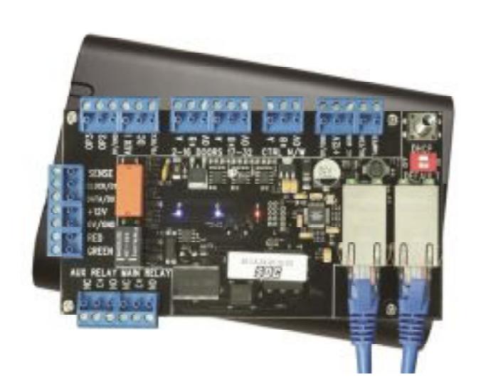
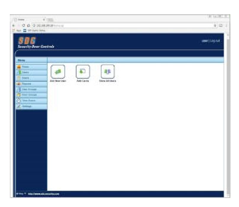
* Visit: sdcsec.com/ippro For Installation video
Table of Contents
|
1.0 Introduction
1.1 System Overview 1 |
|---|
|
2.0 Installation Diagrams
1 2.1 Single Door IPDCE Controller Wiring 2 2.2 Wiring Single IPDCE Controller to One or More IPDSE Remote Door Stations 2.3 Connecting Two or More IPDCE Controllers (PLUS Software recommended) 3 |
|
3.0 Controller Status Indicators
3 |
|
4.0 Quick Start Guide
4-5 |
|
5.0 Controller Configuration
6 5.1 Connecting the Controller to the Network using a Dynamic IP Address (DHCP) 5.2 Connecting the Controller to the Network using the default Static IP Address 6 5.3 Changing the default Static IP Address 7 5.4 Changing the installer (Administrator) Password 7 5.5 Changing a User Name & Password 8 5.6 Setting the Date & Time 8 |
|
6.0 Door Settings
9 6.1 Enable & Name Doors 6.2 Set Door Relay Timers 9 6.3 Set Door Scheduled Actions 9 6.4 Advanced Door Operations 10 6.5 Door Reports Settings 11 6.6 Door Alarms Settings 11 |
|
7.0 Creating Cardholder Access Rights
7.1 Creating a Timezone (Access Schedule) 12 7.2 Creating a Door Group 12 7.3 Creating a User Group 13 7.4 Assigning a User Group to a Cardholder 13 |
|
8.0 Adding Cardholders
14 8.1 Add a Batch of Cards 8.2 Add an Individual Cardholder 14 8.3 Change Cardholder Validity (Temporary Users) 15 8.4 Cardholder Options 15 |
|
9.0 Holiday Scheduling
9.1 Create/View Holidays 16 |
|
10.0 History Reports
10.1 View Log Events 16 10.2 Export Events 17 |
|
11.0 Advanced System Settings
11.1 System Operations 18 11.2 Advanced Door Settings 18 11.3 Tracking 18 11.4 Systemwide Outputs 19 |
|
12.0 Database Backup
12.1 Create a Backup 19 12.2 Restore a Backup 20 |
|
13.0 Specifications
21 |
|
Addendum #1
22 A1.1 Assign a Static IP Address to your PC 23 A1.2 Test Communication to the IP Pro Controller (Ping Test) |
|
Addendum #2
A2.1 Wiring & Programming the 920PW/923PW keypad/card reader for PIN or Card Operation 24 |
|
Addendum #3
24 A3.1 Port Forwarding for Remote Access |
1.0 Introduction
1.1 System Overview
The IP Pro™ Controller (SDC P/N: IPDCE) is an IP-based single door controller. It supports two separate Wiegand readers for true In/Out reader functionality. It may be expanded to two or more openings by adding multiple IPDCE controllers, or with the IP Pro™ Expansion Door Station (P/N: IPDSE). Up to 31 Door Stations may be controlled by a single IP Controller.
The Controller includes an secure, embedded web server which allows installers and users to manage installations without requiring separate software. The web server is easily accessed using a common PC-based web browser (e.g., Microsoft IE, Google Chrome, Mozilla Firefox, etc.)
Both the IPDCE and IPDSE require a 12VDC power source. This requirement may be met by using a traditional 12VDC power supply or by using the IP Pro™ PoE+ Injector (P/N: IPI-30) & Splitter (P/N: IPS-12). The injector/splitter combination allows the controller to connect and be powered using an existing Ethernet network infrastructure. The IPS-12 provides a 12VDC power source capable of powering the controller, reader, and locking device (up to 1.5A total). SDC offers a complete selection of low energy Access Control and Electrified Locking Hardware, guaranteed to work with the IP Pro™ Series controllers.
2.0 Installation Diagrams
2.1 Single Door Wiring
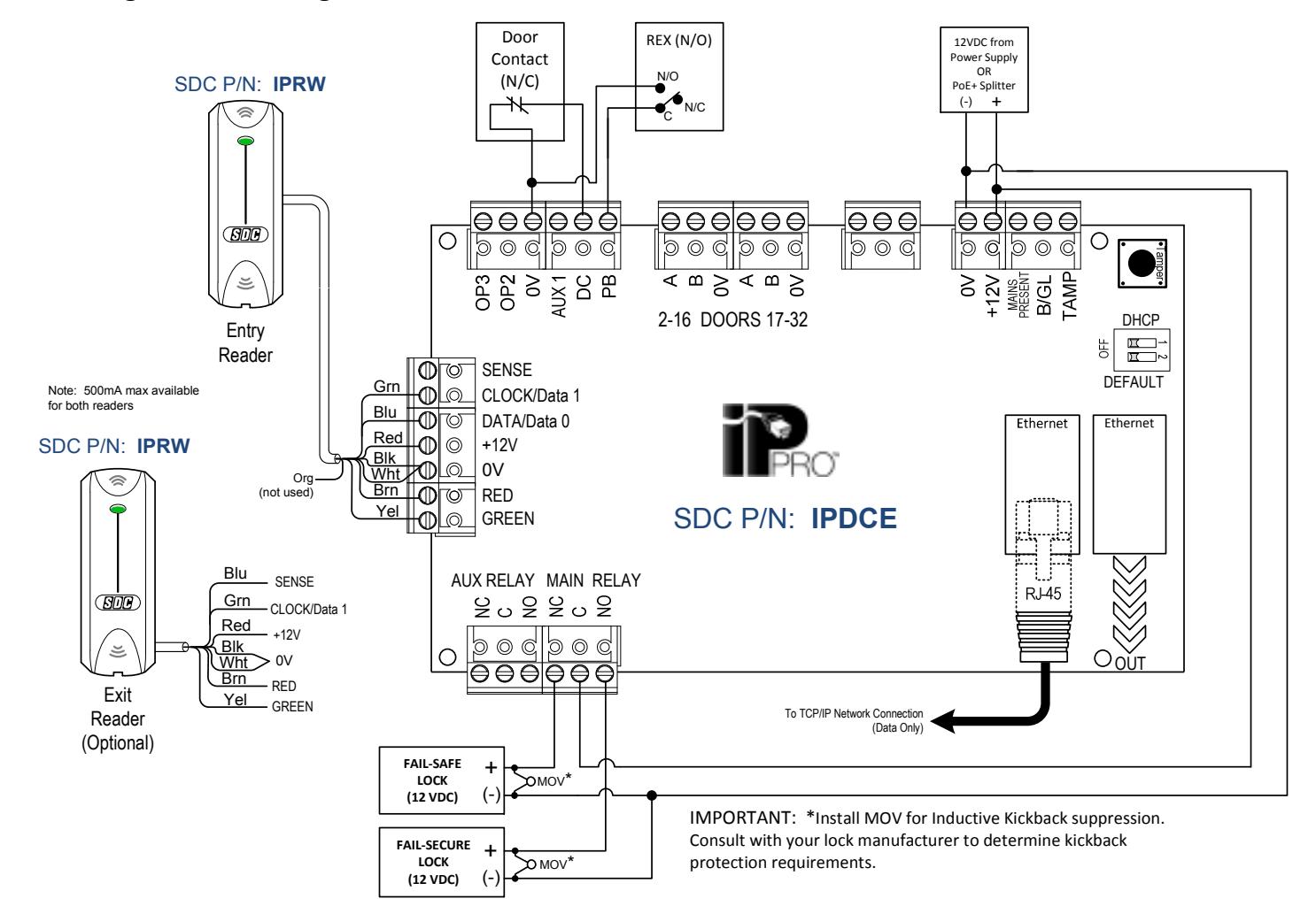
Figure 1. IP Pro™ Single Door Controller – Typical Wiring
2.2 Wiring Two or More Openings (RS-485 Option using with IPDSE's)
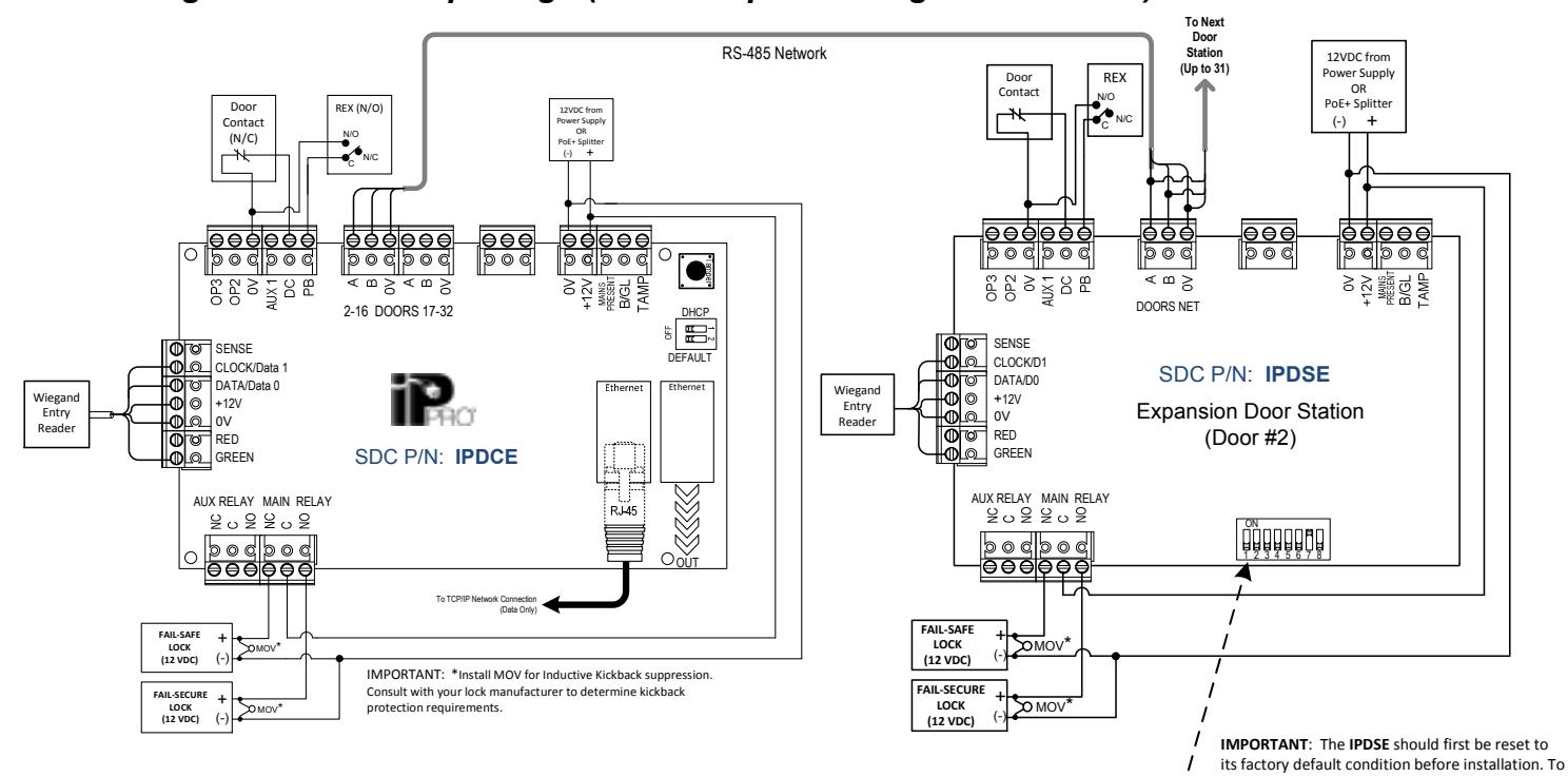
Figure 2. IP Pro™ Single Door Controller with Expansion Door Station(s) — Typical Wiring
RS-485 NETWORK CONNECTIONS
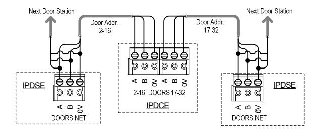
- The Door Stations RS485 network must be daisy chained (star configuration is not permitted).
- The total maximum length of the Door Stations network should not exceed 4000ft.
- On the Door Stations network connect A to A; B to B and 0V to 0V.
- Use twisted pair cable. Shielded cable is recommended for longer distances or areas where Electromagnetic Interference (EMI) is present. West Penn D2402 or similar.
| ĺ | ирр | горис | ite uu | ui css | ||||
|---|---|---|---|---|---|---|---|---|
|
r#
ress_ |
N
2 |
4 | F | 8 | ||||
| 01 | Not | Used | – Res | erved | for IP | DCE | ||
| 02 | OFF | OFF | OFF | OFF | OFF | OFF | ON | OFF |
| 03 | OFF | OFF | OFF | OFF | OFF | OFF | ON | ON |
| 04 | OFF | OFF | OFF | OFF | OFF | ON | OFF | OFF |
| 05 | OFF | OFF | OFF | OFF | OFF | ON | OFF | ON |
| 06 | OFF | OFF | OFF | OFF | OFF | ON | ON | OFF |
| 07 | OFF | OFF | OFF | OFF | OFF | ON | ON | ON |
| 08 | OFF | OFF | OFF | OFF | ON | OFF | OFF | OFF |
| 09 | OFF | OFF | OFF | OFF | ON | OFF | OFF | ON |
| 10 | OFF | OFF | OFF | OFF | ON | OFF | ON | OFF |
| 11 | OFF | OFF | OFF | OFF | ON | OFF | ON | ON |
| 12 | OFF | OFF | OFF | OFF | ON | ON | OFF | OFF |
| 13 | OFF | OFF | OFF | OFF | ON | ON | OFF | ON |
| 14 | OFF | OFF | OFF | OFF | ON | ON | ON | OFF |
| 15 | OFF | OFF | OFF | OFF | ON | ON | ON | ON |
| 16 | OFF | OFF | OFF | ON | OFF | OFF | OFF | OFF |
appropriate address.
do this, power the unit up with ALL 8 switches in the OFF position. The unit will beep after 3
Then power off & use the chart below to set the
seconds. The unit is now defaulted.
Door#
| iui ess | ' | |||||||
|---|---|---|---|---|---|---|---|---|
| 17 | OFF | OFF | OFF | ON | OFF | OFF | OFF | ON |
| 18 | OFF | OFF | OFF | ON | OFF | OFF | ON | OFF |
| 19 | OFF | OFF | OFF | ON | OFF | OFF | ON | ON |
| 20 | OFF | OFF | OFF | ON | OFF | ON | OFF | OFF |
| 21 | OFF | OFF | OFF | ON | OFF | ON | OFF | ON |
| 22 | OFF | OFF | OFF | ON | OFF | ON | ON | OFF |
| 23 | OFF | OFF | OFF | ON | OFF | ON | ON | ON |
| 24 | OFF | OFF | OFF | ON | ON | OFF | OFF | OFF |
| 25 | OFF | OFF | OFF | ON | ON | OFF | OFF | ON |
| 26 | OFF | OFF | OFF | ON | ON | OFF | ON | OFF |
| 27 | OFF | OFF | OFF | ON | ON | OFF | ON | ON |
| 28 | OFF | OFF | OFF | ON | ON | ON | OFF | OFF |
| 29 | OFF | OFF | OFF | ON | ON | ON | OFF | ON |
| 30 | OFF | OFF | OFF | ON | ON | ON | ON | OFF |
| 31 | OFF | OFF | OFF | ON | ON | ON | ON | ON |
| 32 | OFF | OFF | ON | OFF | OFF | OFF | OFF | OFF |
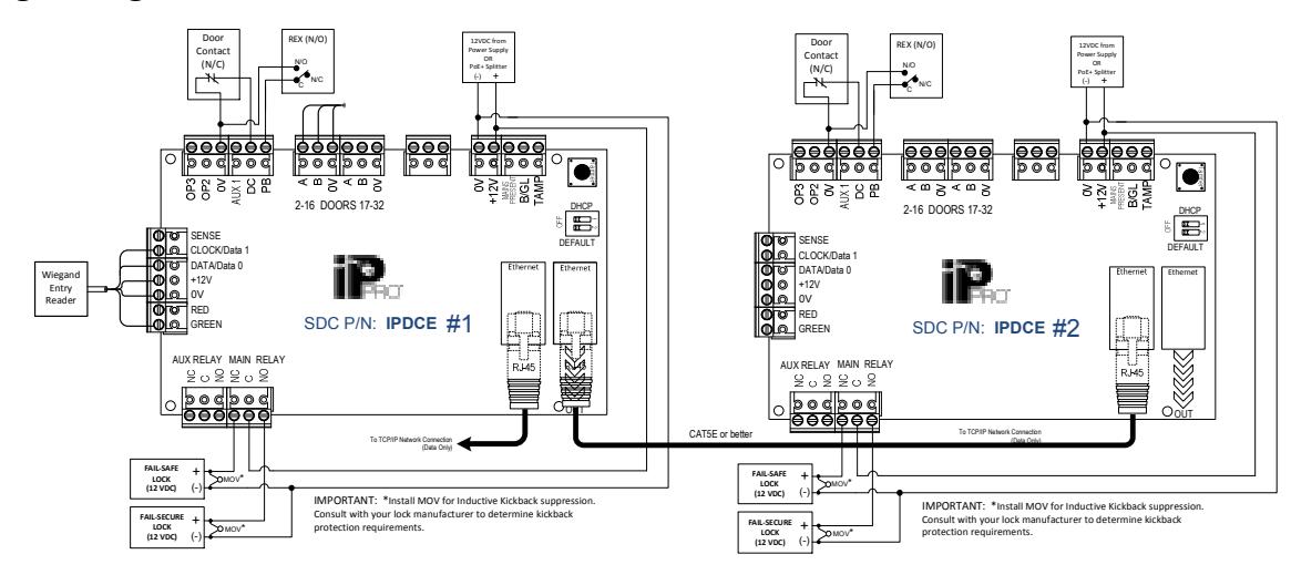
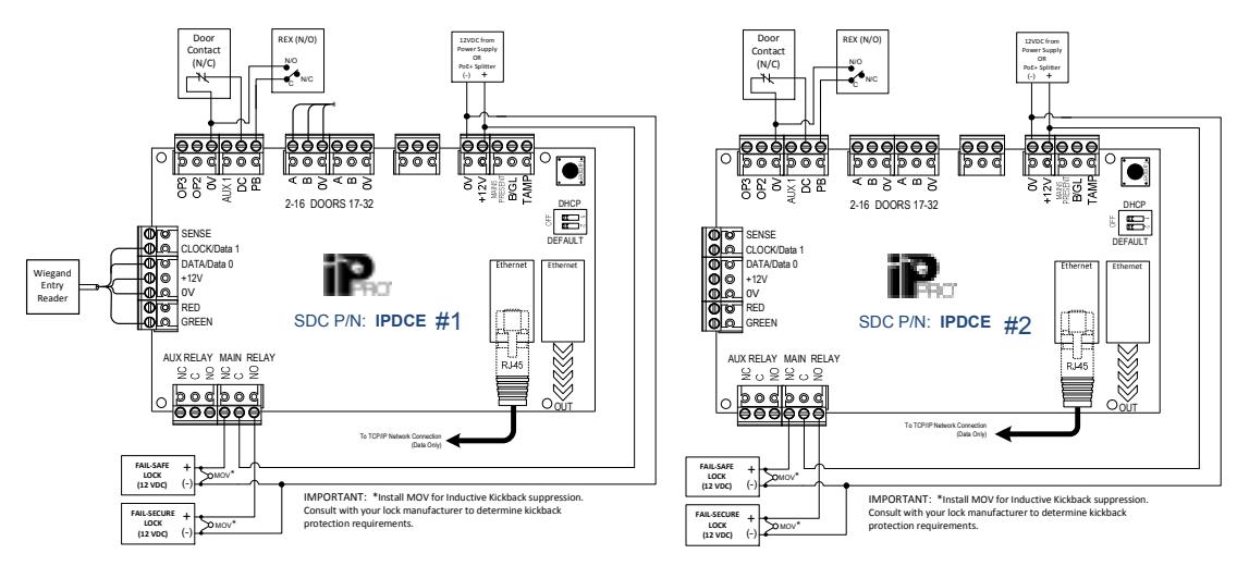
2.3 Connecting Two or More Openings (using Multiple IPDCE's)
NOTE: PLUS software is required & every IPDCE will have a unique IP address, regardless of which of the two options below is used.
Using a single Network Switch Port,
Using a Network Switch Port per IPDCE,
3.0 Controller Status Indicators

Blue: Power
This indicates that the controller has power.

Blue: Communications
Constant illumination indicates that all enabled Door Stations are online.
Flashing indicates that one or more Door Stations are offline.

Red: Fault.
This illuminates to indicate an alarm on the system, possible causes are:
Tamper Open: Controller plastic housing is not closed. In situations where the plastic housing is not being used, connect the TAMP input on the controller PCB to 0V.
Door Station Offline : When one or more enabled door stations is not communicating with the Controller, the Fault LED illuminates and the appropriate indicator on the Door Station will flash.
Low DC Voltage : When voltage to the +12V terminal is less than +9V. Fuse Blown : The +12V output on the READER terminals is current limited to provide short circuit protection. The Fault LED will illuminate if too much current is pulled from this connection.
AC Mon or BG/EDR Inputs Open : If either of these inputs are turned ON in programming, the input terminal on the board must be shorted or it will report a fault.
4.0 Quick Start Guide
Step 1 :
Connect the IP Pro Door Controller directly to your PC or laptop using an standard or crossover Ethernet cable (CAT5 or better). The Controller is defaulted to use a static (fixed) IP address. The default static IP address is 192.168.1.60 . Refer to Addendum #1 to configure your PC with the following Ethernet adapter settings:
3
Static IP address: 192.168.1.100 (for example)
Default Netmask: 255.255.255.0 Default Gateway: 192.168.1.1
Step 2 :
Open a web browser on your Windows PC (Microsoft Internet Explorer, Mozilla Firefox, or Google Chrome).
NOTE: Minimum PC requirements are Windows 7, 8, or 10.
Step 3 :
Enter http://192.168.1.60 in the URL bar.
You will be prompted for authentication credentials.
Step 4 :
Login to the Controller as installer
Login credentials: Username: installer Password: 999999
Step 5 : Update Communication Settings.

5b . You may change the Static IP address, Network mask, and Default Gateway, as required, and click Save . Changing these settings will reset the controller and require you to return to Step 2 . If the default settings are acceptable, skip to Step 6 .

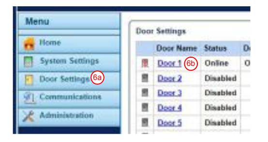
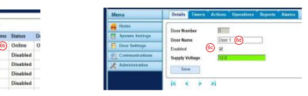
6a . Select " Door Settings " from the menu, which lists all 32 doors.
6b. Select the Door Name (e.g., Door 1) to be enabled.
6c. Check the Enabled box. NOTE: Door 1 is always the IP Door Controller. It will be enabled by default.
6d. Edit the Door Name field, as required, up to 16 characters in length. Click Save .
5a
5b
Step 7:
Logout from installer menu (top right corner).
Step 8:
Login to controller as user
Login details: Username: user Password: 123456
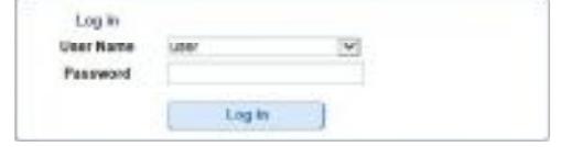
Click Log In.
Step 9 : Add User Card(s) – Must be sequential
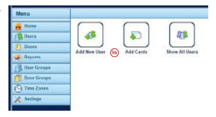
- 9a. From the Home Menu, select " Add Cards " by clicking on the icon
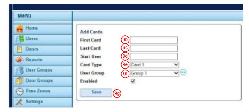
- 9b. Enter the " First Card " number.
NOTE: For a 26-bit Wiegand reader, the card number consists of a 3-digit facility code + a 5-digit card number (typically printed on the card). For example, if a card has a facility code of '110' and the number printed on the card is '01234', then the number entered into the "First Card" field will be '11001234'.
- 9c . Enter the " Last Card " number.
- 9d . Set the " Start User " to '1' (for a new installation)
- 9e . Set the "Card Type" to 'Card 1'. Each user may be assigned up to 2 separate credentials (Card 1 or Card 2).
- 9f. Set the " User Group " to 'Group 1', and check the Enabled box.
NOTE: User Group #1 is enabled by default. By default, ALL users in Group #1 will have 24/7 access to ALL Doors.
9g . Click Save .
Step 10 : Set the Controller Date & Time
- 10a. Select the Settings option from the Menu.
- 10b. Select the Date and Time tab.
- 10c . Enter the Date. Enter the 2-digit Month (MM), 2-digit Day (DD), and 4-digit Year (YYYY).
- 10d . Click Save.
- 10e . Enter the Time. 2-digit hour (HH, 24hr clock), and 2-digit minutes (MM).
- 10f. Click Save .
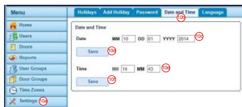
The IP Pro ™ Door Controller is now ready for use. Logout and close your browser.
5.0 Controller Configuration
The IP Pro™ Controller has two pre-defined user accounts: i nstaller & user .
installer account – Used to configure global communications and door settings.
Login credentials: Username: installer Password: 999999
user account – Used for day to day management of the system, such as managing users and access rights.
Login credentials: Username: user Password: 123456
5.1 Connecting the Controller to the Network using a Dynamic IP Address (DHCP)
Step 1: The Controller is defaulted for a static IP address. To enable DHCP, remove power from the Controller.
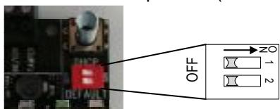
Step 2: Set DIP switch 1 to the ON position (i.e., Move DIP switch 1 to the right).
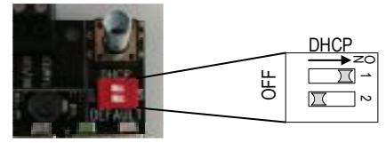
- Step 3: Connect the Door Controller to IP network and apply power to the Controller
- Step 4: Open a compatible web browser from any Windows PC on your network (Internet Explorer, Mozilla Firefox, or Google Chrome). NOTE: Minimum PC OS requirement is Windows 7, 8, or 10.
- Step 5: To Login, enter http://ippro- (followed by the NetBIOS address ).
e.g. http://ippro-13407 (see label on PCB)
NetBIOS address = last 5 digits
You will be prompted for authentication credentials. It is recommended that you change the Static IP address (see Section 5.3) and always use the new static IP address to when connecting to the Controller.
5.2 Connecting the Controller to a PC using the default Static IP Address
Step 1: Remove power from the Controller and verify that the Controller is defaulted to use a static (fixed) IP address. DIP switch 1 will be set to the OFF position (i.e., to the left).
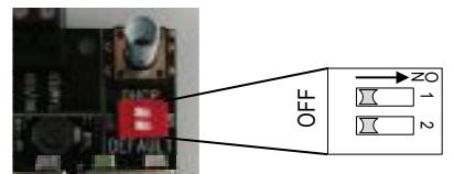
Step 2: The default static IP address is 192.168.1.60 . Verify that your PC is on the same subnet as the controller or Refer to Addendum #1 to configure your PC with the following Ethernet adapter settings:
Static IP address: 192.168.1.100 (for example)
Default Netmask: 255.255.255.0 Default Gateway: 192.168.1.1
Step 3: Open a web browser on your PC (Internet Explorer, Mozilla Firefox, or Google Chrome).
NOTE: Minimum PC OS requirement is Windows 7, 8, or 10.
Step 4: To Login, enter http://192.168.1.60. You will be prompted for authentication credentials.
5.3 Changing the default Static IP Address
- Step 1: Login as "installer"
- Step 2: Select "Communications" from the Menu.
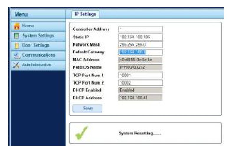
- Step 3: Change the Static IP address, Network Mask, and Default Gateway, as required, and click Save.
- Step 4: The following message will appear:
"Changes to IP settings may require reset
Do you wish to continue?"
Click OK.
Step 5: After "System Resetting......." & the green checkmark appear, Close the browser.
- Step 6: If DHCP is enabled, remove power from the Controller. If DHCP is disabled, skip to Step 8.
- Step 7: Set DIP switch 1 to the OFF position (as shown), then re-apply power.
Step 8: To Login, open a web browser an enter http://(New Static IP Address). e.g., http://192.168.100.185
5.4 Changing the installer (Administrator) Password
NOTE: Passwords must be 6-16 characters, numbers or letters, and are case-sensitive.
- Step 1: Login as "installer"
- Step 2: Select "Administration" from the Menu.
- Step 3: Click on the "Password" tab
- Step 4: Next to the installer user field,
- enter a new password.
- Step 5: Click Save.
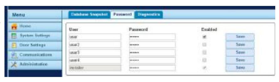
Warning : It's important that the installer password be different from all user passwords, and be retained in a secure location. If the installer code is lost, a factory default will be required.
5.5 Changing a User Name & Password
NOTE: Passwords must be 6-16 characters, numbers or letters, and are case-sensitive.
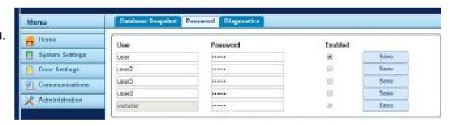
There are four "user level" accounts available for access to the management software. To edit these users:
- Step 1: Login as " installer "
- Step 2: Select " Administration " from the Menu.
- Step 3: Click on the " Password " tab
- Step 4: Edit the User Name and associated password, as necessary.
- Step 5: Verify that the Enabled box is checked.
- Step 6: Click Save.
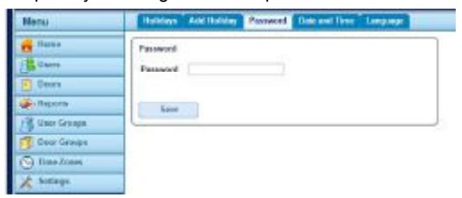
Additionally, each user level account has the capability to change their own password:
- Step 1: Login as a user level account.
- Step 2: Select " Settings " from the Menu.
- Step 3: Click on the " Password " tab
- Step 4: Enter the new password.
- Step 5: Confirm the new password
- Step 6: Click Save.
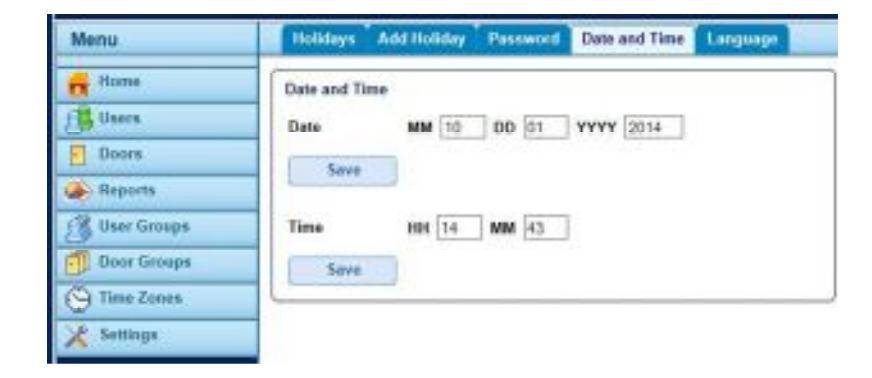
5.6 Setting the Date & Time
- Step 1: Login as a user level account
- Step 2: Select the Settings option from the Menu.
- Step 3: Select the Date and Time tab.
- Step 4: Enter the Date. Enter a 2-digit Month (MM), 2-digit Day (DD), and 4-digit Year (YYYY).
- Step 5: Click Save.
- Step 6: Enter the Time. Enter a 2-digit hour (HH, 24hr clock), and 2-digit minutes (MM).
- Step 7: Click Save .
6.0 Door Settings
6.1 Enable and Name Doors
- Step 1: Login as installer
- Step 2: Select " Door Settings " from the Menu
- Step 3: Select the desired door (e.g., Door 1)
- Step 4: Check the Enabled box
- Step 5: Edit the Door Name field, as required.
- Step 6: Click Save .
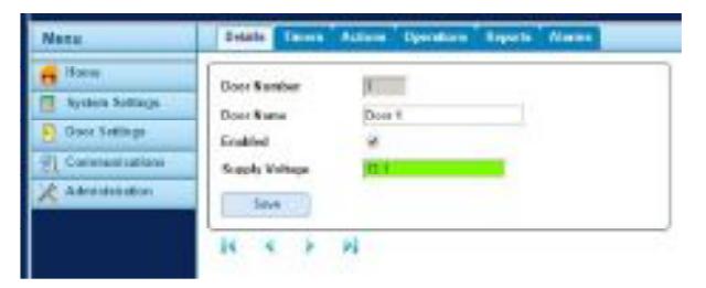
You may use the arrow buttons to navigate to the next door or click Door Settings from the Menu to view all doors.
6.2 Set Door Relay Timers
- Step 1: Login as installer
- Step 2: Select " Door Settings " from the Menu
- Step 3: Select the desired door (e.g., Door 1)
- Step 4: Select the " Timers " tab
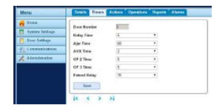
Step 5: Use the drop-down menu to adjust each timer, as required.
| Field Name | Description |
|---|---|
| Relay Time | Time the main relay is activated in response to a valid card or to operation of the request-to-exit switch. |
| Ajar Time | Time the door may remain open before a door ajar (held open) condition occurs. |
| AUX Time | Time the AUX (alarm) output is activated. |
| OP2 Time | Time the OP2 output is activated. |
| OP3 Time | Time the OP3 output is activated. |
| Extend Relay Time the door relay is activated in response to a valid card for a user with the Extend Relay option. In this case, the door | |
| relay is activated for an extended period of time for users who may require longer to access the door. |
Step 6: Save
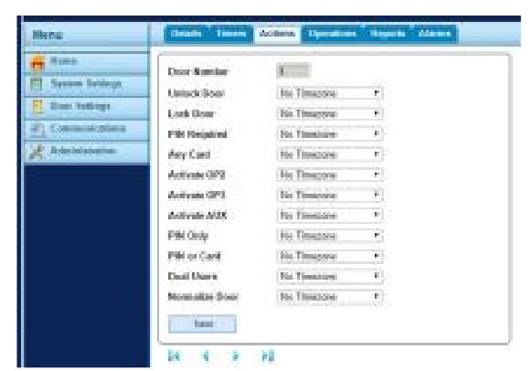
6.3 Set Door Scheduled Actions
- Step 1: Login as installer
- Step 2: Select " Door Settings " from the Menu
- Step 3: Select the desired door (e.g., Door 1)
- Step 4: Select " Actions " tab
- Step 5: Using the drop-down menu, select a Timezone to determine when the Action will be executed. Refer to Section 7.1 Creating a Timezone.
Step 6: Click Save
| Field Name | Description |
|---|---|
| Unlock Door | The assigned Timezone determines when the door is automatically unlocked, allowing free access. The main relay is held open, and the green reader LED will flash. |
| Lock Door | The assigned Timezone determines when the door is automatically locked. When a door is locked, all users will be denied access regardless of their programmed |
| access rights. The door relay is held closed for this time. | |
| The assigned Timezone determines when Card and PIN operation is enforced on the door. When a card is presented during this time, a valid user or group PIN must | |
| PIN Required | be entered to gain access. |
| Any Card | The assigned Timezone determines when ANY card will be allowed access. The only check performed is that a card is presented: the format is irrelevant. |
| Activate OP2 | The assigned Timezone determines when the OP2 output is active. This could be used to control an externally connected device. |
| Activate OP3 | The assigned Timezone determines when the OP3 output is active. |
| Activate AUX | The assigned Timezone determines when the AUX output is active. |
| The assigned Timezone determines when PIN Only operation is enforced for the door. During this time, all presented cards will be ignored, and a valid user PIN must | |
| PIN Only | be entered to gain access. |
| PIN or Card | The assigned Timezone determines when either a valid PIN or Card operation is required to gain entry. |
| Dual Users | The assigned Timezone determines when two valid cards must be presented to gain access. |
| Normalize Doors The assigned Timezone determines when the door is normalized(i.e., the door returns to its default state.) |
6.4 Advanced Door Operations
- Step 1: Login as installer
- Step 2: Select " Door Settings " from the Menu
- Step 3: Select the desired door (e.g., Door 1)
- Step 4: Select " Operations " tab
- Step 5: Select the checkbox next to the operations setting to be applied to the selected Door.
Step 6: Click Save
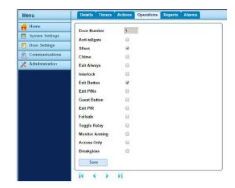
| Field Name | Description |
|---|---|
| Anti-tailgate | When selected, the main relay time expires one second after the door is opened. NOTE: A door contact must be connected AND Door Contact must |
| be checked under the Reports tab. | |
| Silent | By default, the door controller gives an audible indication when a card is swiped. When selected, the audible indication is suppressed. |
| Chime | When selected, the door controller's buzzer sounds momentarily when the door is opened. The Auxiliary output is also activated for a short period of |
| time. NOTE: If the Silent option is also selected, the controller's buzzer will not sound, but the auxiliary output will still activate momentarily. | |
| Exit Always | Normally, the controller applies the same group access rules to users exiting the area as it applies to users being granted access. If this option is |
| selected, normal access rights are ignored and any enabled card can exit irrespective of access rights. | |
| Interlock | If selected, only one door of a connected 2-door interlock may be open/unlocked at any one time. The interlock output (OP3) of each door should be |
| connected to the interlock input (AUX) of the other door. Interlock must be selected on both door controllers. NOTE: 0V lines of both controllers | |
| should be connected together. | |
| Exit Button | If selected, the request-to-exit input (PB) is enabled. When this switch is momentarily closed, the relay timer is activated for its programmed period |
| of time. An exit event may also be recorded in the system log. | |
| Exit PINs | Normally in PIN only or Card + PIN operation, PIN codes are used only to gain entry through the door. When selected, the controller requires a PIN |
| code when exiting also. | |
| Guest Button | When an external keypad is being used to gain entry, this option allows the "Bell" button on the keypad to be used to momentarily fire a guest |
| buzzer connected to the auxiliary output of the controller. | |
| Exit PIR | If selected, a Passive Infrared (PIR) device can be used in place of a traditional push button exit switch. The main relay remains unlocked past the |
| relay timer, while the PIR is active. | |
| Failsafe | When using normally energized locking devices, there may be problems with the door remaining locked during a power outage when a stand-by |
| battery is discharging. If this option is selected, the action of the relay is reversed so that the door will fail open in a power outage. | |
| Toggle Relay |
If selected, the door can be toggled open or closed by users with the Toggle Relay option enabled.
(See Section 8.4) |
| Monitor Arming | The AUX input on the controller may be connected to a keyswitch or ON/OFF switch. When this signal is low, the controller denies access to users. |
| Access Only | If selected, the main relay output at the access point is activated if a valid card is presented at an access reader. |
| Breakglass | If selected, the auxiliary output relay is activated when the B/GL input reads an open circuit. |
6.5 Door Reports Settings
Step 1: Login as installer
Step 2: Select " Door Settings " from the Menu
Step 3: Select the desired door (e.g., Door 1)
Step 4: Select " Reports " tab
Step 5: Select the checkbox next to the event types to be reported.
Step 6: Click Save
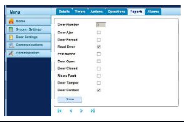
| Field Name | Description |
|---|---|
| Door Ajar | A door ajar event is logged if the door has been open for longer than a predetermined period of time. |
| Door Forced | A door forced event is logged if the door is opened without being explicitly commanded to open by the controller. This would typically occur if |
| the locking mechanism is bypassed or if the door is physically forced open. | |
| Read Error | A read error event is logged when an incorrect read occurs on an entry or exit reader. An additional error number may be displayed giving further |
| details on the error. | |
| Exit Button | An exit granted (push button) event is logged when a user presses the request-to-exit (egress) switch. |
| Door Open | A door opened event is logged when the door is physically opened. Door contact required. |
| Door Closed | A door closed event is logged when the door is physically closed. Door contact required. |
| Mains Fault | A mains fault event is logged if the primary supply fails. A normally closed, dry contact must be connected to the Mains Present input on the |
| controller. | |
| Door Tamper | A door tamper event is logged if the door is tampered with, that is, if the door station or controller tamper switch is activated. |
| Door Contact | This is required for a door opened/closed event to be visually annunciated on the Door Settings screen. |
6.6 Door Alarms Settings
Use this tab to determine which Alarm conditions will activate the Auxiliary Relay.
Step 1: Login as installer
Step 2: Select " Door Settings " from the Menu
Step 3: Select the desired door (e.g., Door 1)
Step 4: Select " Alarms " tab
Step 5: Select the checkbox next to the condition which will activate the Auxiliary Relay.
Step 6: Click Save
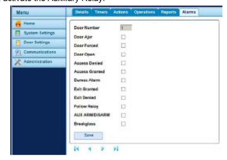
| Field Name | Description |
|---|---|
| Door Ajar | The AUX output is activated if the door has been open for longer than a predetermined period of time. It is reset once the door is closed or when a valid |
| card is swiped. | |
| Door Forced | The AUX output is activated if the door is opened without being explicitly commanded to open by the controller. It is reset when a valid card is swiped. |
| Door Open | The AUX output is activated while the door is open. |
| Access Denied | The AUX output is activated for 2 seconds if an invalid card is swiped. |
| Access Granted | The AUX output is activated if a valid card is swiped. |
| Duress Alarm | The AUX output is activated if a duress PIN code is entered. This is when a number 1 greater than the valid PIN is entered in PIN Only or PIN & Swipe |
| operation. | |
| Exit Granted | The AUX output is activated if a valid card is presented at an exit reader. |
| Exit Denied | The AUX output is activated for 2 seconds if an invalid card is swiped at an exit reader. |
| Follow Relay | If selected, while the main relay is active, the AUX relay is also active. |
| AUX ARM/DISARM Must be used in conjuction with Door Settings - Operations - Monitor Arming | |
| Breakglass | Must be used in conjuction with Door Settings - Operations - Breakglass |
7.0 Creating Cardholder Access Rights
To create access rights, every cardholder must be assigned a User Group. A User Group consists of two elements:
Timezones (Section 7.1) and Door Groups (Section 7.2). NOTE: By default, all User Groups are enabled, and have been given 24/7 access to all enabled doors.
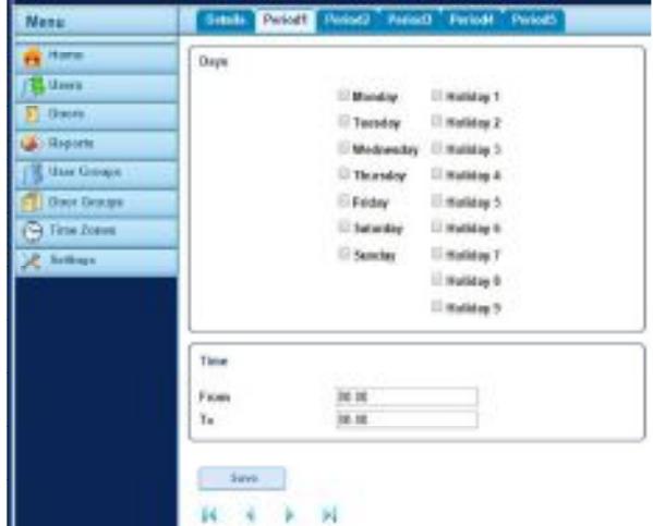
7.1 Creating a Timezone
There are two pre-defined timezones: " No Timezone " and " 24 Hours ". The pre-defined timezones cannot be edited.
To create a new Timezone,
- Step 1: Login as a user level account.
- Step 2: Select " Time Zones " from the Menu.
- Step 3: Choose a Timezone Name from the Timezone List (e.g., Timezone 1)
- Step 4: From the Details Tab, assign a unique Name to the Timezone, and Click Save .
- Step 5: Select one of the five time period tabs to edit.
- Step 6: From the Period Tab, select the Day(s) for which the Timezone will be active.
- Step 7: If required, select a Holiday (Type 1 thru 9) when the Timezone will be active. Refer to Section 9.1 Create/View Holidays .
- Step 8: Edit the Time when the Timezone will be active (00:00 to 23:59)
- Step 9: If necessary, select and edit another Period.
- Step 10: Click Save .
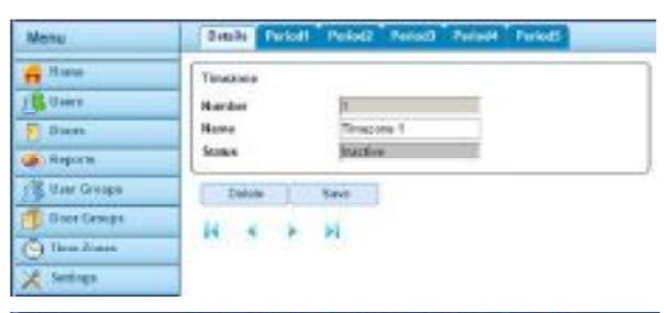
7.2 Creating a Door Group
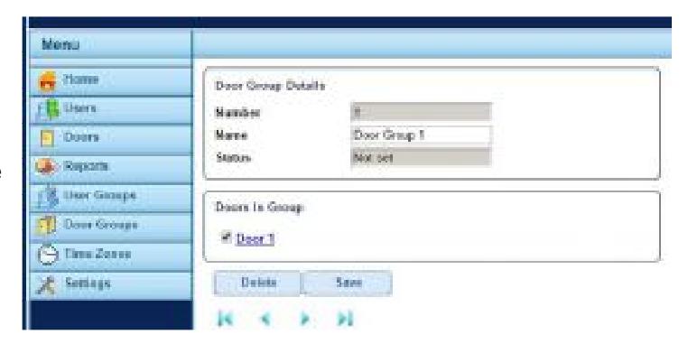
There are two pre-defined Door Groups: " No Doors " and " All Doors ". The pre-defined door groups cannot be edited.
To create a new Door Group ,
- Step 1: Login as a user level account.
- Step 2: Select " Door Groups " from the Menu.
- Step 3: Choose a Door Group Name from the Door Group List (e.g., Door Group 1)
- Step 4: Under Door Group Details, assign a unique Name to the Door Group.
- Step 5: Check the box next to the Door(s) which are part of the Door Group. NOTE: Only Enabled doors will be available to add to the Door Group.
- Step 6: Click Save .
7.3 Creating a User Group
NOTE: By default, all User Groups are enabled, and have been given 24/7 access to ALL enabled doors.
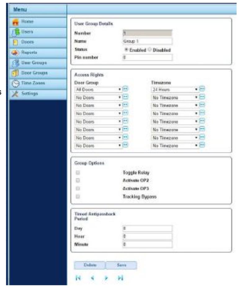
To create a new User Group,
- Step 1: Login as a user level account.
- Step 2: Select " User Groups " from the Menu.
- Step 3: Choose a User Group Name from the List of Groups (e.g., Group 1)
- Step 4: Under User Group Details, assign a unique Name to the User Group.
- Step 5: Under Access Rights, use the drop-down menus to assign Door Groups and their respective Timezones. (Up to 8 per Group)
- Step 6: Check any Group Options, as required. See descriptions below. Note: A different setting on the User's Options Tab (See Section 8.0 – Cardholder Settings ) overrides this setting.
- Step 7: To enable anti-passback, set the timed anti-passback period to any other value than 0 days, 0 hours, and 0 minutes. The minimum is 1 minute. The maximum is 7 days, 23 hours, and 59 minutes. See description below.
- Step 8: Click Save .
| Option Name | Description |
|---|---|
| Toggle Relay | This option causes the relay to toggle whenever a user in this group is granted access. If the door is in its normal state, it will be held unlocked, and the green reader LED |
| will flash. If the door was already unlocked, then it is returned to normal operation. | |
| Activate OP2 | This option causes the local OP2 output to be fired for a predetermined period of time whenever a user in this group is granted access. |
| Activate OP3 | This option causes the local OP3 output to be fired for a predetermined period of time whenever a user in this group is granted access. |
| Tracking Bypass | This option allows tracking functions to be bypassed for users in this group. This means that anti-passback and user-limiting functions do not apply to users in this group. |
| Timed | When a user in the Group is granted access through a door, then the user will not be granted access again until the anti-passback time period expires. |
| Antipassback | |
| Period |
7.4 Assigning a User Group to a Cardholder.
Refer to Section 8.0 for Cardholder configuration.
8.0 Adding Cardholders
8.1 Add a Batch of Cards
Step 1: Login as a user level account.
Step 2: From the Home screen, select the " Add Cards " icon
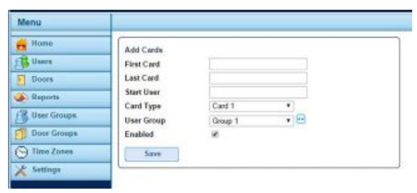
Step 3: Enter the " First Card " number.
NOTE: For a 26-bit Wiegand reader, the card number consists of a 3-digit facility code + a 5-digit card number (typically printed on the card). For example, if a card has a facility code of '110' and the number printed on the card is '01234', then the number entered into the "First Card" field will be '11001234'.
Step 4: Enter the " Last Card " number.
Step 5: Set the " Start User " to '1' (for a new installation)
Step 6: Set the "Card Type" to 'Card 1' or 'Card 2'. Each user may be assigned up to 2 separate credentials (Card 1 or Card 2). If Card 1 has not been used, use Card 1 first.
Step 7: Select a " User Group " and check the Enabled box.
NOTE: Checking Enabled in Step 7 above enables all the cardholders. User Groups may also need to be enabled (See Section 7.3 Creating a User Group )
Step 8: Click Save .
8.2 Add an Individual Cardholder
Step 1: Login as a user level account.
Step 2: Select " Users " from the Menu
Step 3: From Show All Users, select a User Name (e.g., User 1)
Step 4: Under User Details, edit the User name
Step 5: Using the drop-down menu, Select a User Group
Step 6: Under Status, select " Enabled "
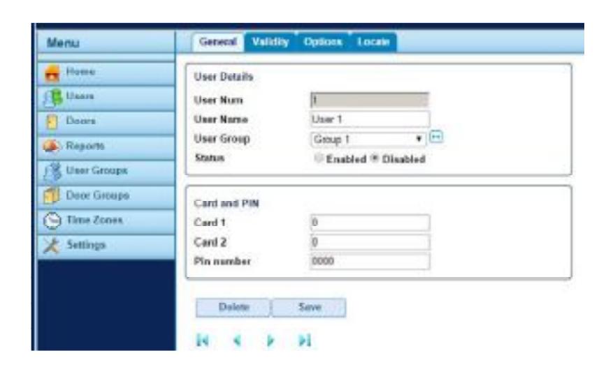
Step 7: Enter card number into either Card 1 or Card 2 field
NOTE: For a 26-bit Wiegand reader, the card number consists of a 3-digit facility code + a 5-digit card number (typically printed on the card). For example, if a card has a facility code of '110' and the number printed on the card is '01234', then the number entered into the "First Card" field will be '11001234'.
Step 7: Click Save
8.3 Change Cardholder Validity (Temporary User)
By default, a user card is always valid and never expires. To change the period of time a cardholder is valid,
- Step 1: Login as a user level account.
- Step 2: From the Home screen, select " Users " from the Menu.
- NOTE: If this is a new user, go to Section 8.2, and return to Step 4 after the new cardholder has been added.
- Step 3: From Show All Users, select a User Name (e.g., User 1 )
- Step 4: Select the Validity Tab.
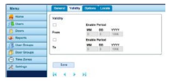
- Step 5: Check the box above "From" to enable the Start Date. Enter a 2-digit Month (MM), 2-digit Day (DD), and 4-digit Year (YYYY). This is the first day the card will be valid.
- Step 6: Check the box above "To" to enable the End Date. Enter a 2-digit Month (MM), 2-digit Day (DD), and 4-digit Year (YYYY). This is the last day the card will be valid.
- Step 7: Click Save .
8.4 Cardholder Options
- Step 1: Login as a user level account.
- Step 2: From the Home screen, select " Users " from the Menu.
- Step 3: From Show All Users, select a User Name (e.g., User 1 )
- Step 4: Select the Options Tab.
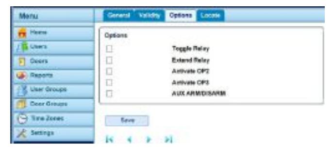
Step 5: Check the box next to the desired option(s).
| Field Name | Description |
|---|---|
| Toggle Relay | This option causes the relay to toggle whenever the user is granted access. If the door was in its normal state, it is unlocked, and the green reader LED will |
| flash. If the door was already unlocked, then it is returned to normal operation. This option may be assigned to individual users or to groups. | |
| Extend Relay | This option causes the door relay to remain active for an extended period of time when access is granted. The time is determined by the Extend Relay |
| Timer (See Section 6.2) | |
| Activate OP2 | This option causes the local OP2 output to be fired for a predetermined period of time whenever the user is granted access. |
| Activate OP3 | This option causes the local OP3 output to be fired for a predetermined period of time whenever the user is granted access. |
| AUX ARM/DISARM This option is not available on the IP Pro Door Controller. |
9.0 Holiday Scheduling
9.1 Create/View Holidays
- Step 1: Login as a user level account.
- Step 2: From the Home screen, select " Settings " from the Menu.
- Step 3: Select the " Add Holiday " Tab.
- Step 4: Enter the 2-digit month (MM) and 2-digit day (DD) for the desired holiday.
- Step 5: Use the drop-down menu to select the holiday type. There an 9 possible Holiday Types.
Step 6: Click Save .
To view all Holidays, select the Holidays Tab.
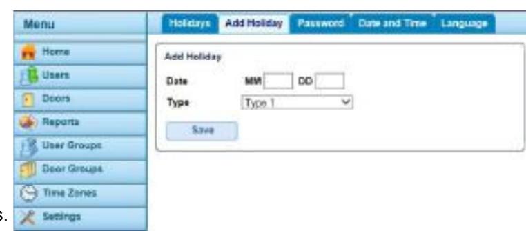
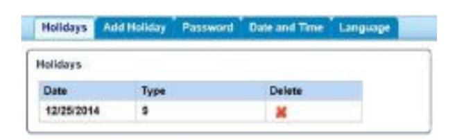
NOTE: User Groups that have been assigned the " 24 Hours " Timezone will have normal access on Holidays. User Groups assigned to any other Timezone will only have access for Holiday Types selected in their respective Timezone period (See Section 7.1).
10.0 History Reports
10.1 View Log Events
- Step 1: Login as a user level account.
- Step 2: From the Home screen, select " Reports " from the Menu.
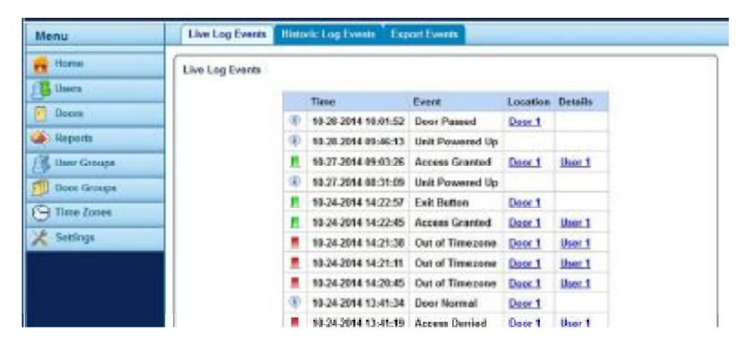
The Live Log Events tab lists the previous 25 events.
The Historic Log Events tab lists the previous 5000 events (25 events at a time). Use the arrow buttons to page through the events.
When either log becomes full, the list will drop the oldest event (first in, first out).
10.2 Export Events
Events may be exported as a .csv format file, viewable & editable in Microsoft Office Excel. It is recommended that events be exported using Internet Explorer or Mozilla Firefox.
- Step 1: Login as a user level account.
- Step 2: From the Home screen, select " Reports " from the Menu.
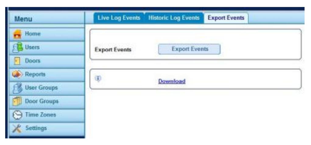
- Step 3: Select the " Export Events " tab. The download link will appear.
- Step 4: Click the Download link.
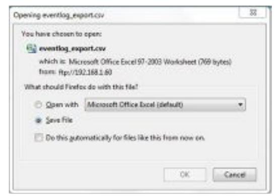
Using Firefox, a window similar to this one will appear:
Click OK to Save the file. The 'eventlog_export.csv' file will be saved to the local Downloads folder.
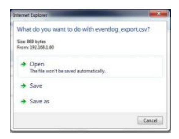
Using Internet Explorer, a window similar to this one will appear:
Click Save as to rename the file or to change the location where the file is to be saved.
11.0 Advanced System Settings
The following settings are Global (Systemwide) and will apply to all controllers and door stations on the RS485 network.
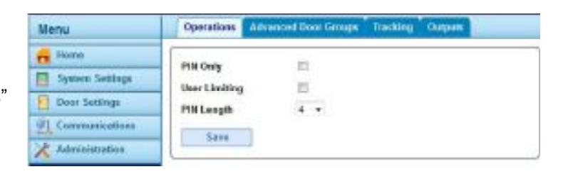
11.1 System Operations
- Step 1: Login as installer .
- Step 2: From the Home screen, select " System Settings " from the Menu.
- Step 3: Select the Operations Tab.
- Step 4: Edit the fields as required.
- Step 5: Save
| Field Name | Description |
|---|---|
| PIN Only | If selected, PIN Only operation is required on the entire system. No card credentials are accepted in the system. |
| User Limiting | If selected, when the number of users inside the perimeter area is equal to the maximum of either User Limit A or User Limit B |
| then the controller prevents any more users from entering. | |
| PIN Length | Using the drop-down menu, selects the number of digits required for all cardholder PIN numbers used in Card & PIN mode, |
| PIN Only mode, PIN or Card mode. Default = 4 digits. |
11.2 Advanced Door Groups
- Step 1: Login as installer .
- Step 2: From the Home screen, select " System Settings " from the Menu.
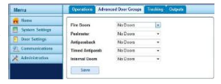
- Step 3: Select the Advanced Door Groups Tab.
- Step 4: Using the drop-down menus, select the appropriate door group to assign as Fire Doors, Perimeter Doors, etc.
Step 5: Save
| Field Name | Description |
|---|---|
| Fire Doors | The designated Door Group automatically opens in the event of a fire to allow free passage. A signal from the fire alarm |
| system to the AUX1 input is required. | |
| Perimeter | The designated Door Group contains doors on the perimeter of the installation. This allows the system to keep track of which |
| users are in or out of the installation at a given time. See Tracking (Section 11.3) | |
| Antipassback | The designated Door Group defines which doors are in the Anti-passback area. Doors in this area must have entry/exit |
| readers. | |
| Timed Antipassb | The designated Door Group contains doors that will not re-open for the same card during the anti-passback timed period. The |
| anti-passback timed period is defined in the User Groups (Section 7.3) | |
| Internal Doors | The designated Door Group contains doors inside the perimeter of the installation. These doors deny access if the cardholder |
| has not already entered through the perimeter or anti-passback doors. |
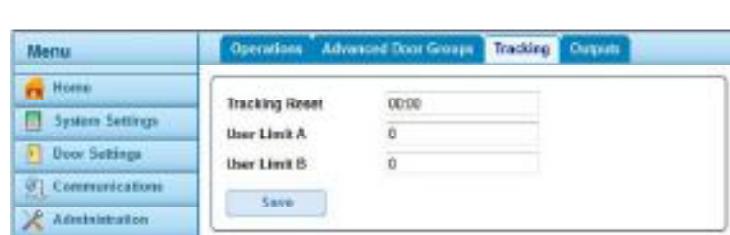
11.3 Tracking
- Step 1: Login as installer .
- Step 2: From the Home screen, select " System Settings " from the Menu.
- Step 3: Select the Tracking Tab.

11.4 Systemwide Outputs
- Step 1: Login as installer .
- Step 2: From the Home screen, select " System Settings " from the Menu.
- Step 3: Select the Outputs Tab.
- Step 4: Check outputs as required, and Save .
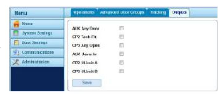
| Field Name | Description |
|---|---|
| AUX Any Door | When this option is selected, the AUX output on the IP Door Controller operates if the AUX output for any of the door stations |
| connected to the controller is active. | |
| OP2 Tech Flt | When this option is selected, the AUX output on the IP Door Controller operates if a technical fault condition exists. Technical |
| faults include mains faults, tampers or doors offline. | |
| OP3 Any Open | When this option is selected, the OP3 output on the IP Door Controller operates if any of the doors connected to the controller |
| are open. | |
| AUX Users In | When this option is selected, the AUX output on the IP Door Controller operates while one or more users are within the anti |
| passback or perimeter area (if configured). The output activates immediately when a user enters the defined area, and de | |
| activates when all users have exited. | |
| OP2 ULimit A | When this option is selected, the OP2 output on the IP Door Controller operates when the number of users within the anti |
| passback or perimeter area reaches or exceeds User Limit A | |
| OP3 ULimit B | When this option is selected, the OP3 output on the IP Door Controller operates when the number of users within the anti |
| passback or perimeter area reaches or exceeds User Limit B |
12.0 Database Backup
12.1 Create a Backup
It is recommended that Microsoft Internet Explorer or Mozilla Firefox be used for database backups. To create a backup of the system database on your PC:
- Step 1: Login as installer .
- Step 2: From the Home screen, select " Administration " from the Menu.
- Step 3: From the Database Snapshot Tab, Click Create Snapshot . The Last Snapshot Taken field will update & the backup now link will appear. A database backup file named ippro_snapshot.dbo has been created on the controller.
- Step 4: Click the Backup now link.
If using Internet Explorer, select Save as when prompted.

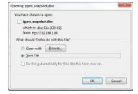
If using Firefox, click OK when prompted to save the file to the local Downloads folder.
12.2 Restore a Backup
To restore the backup from the PC the installer must use an FTP client. The FTP client can be run from the command line or using an FTP client such as Filezilla.
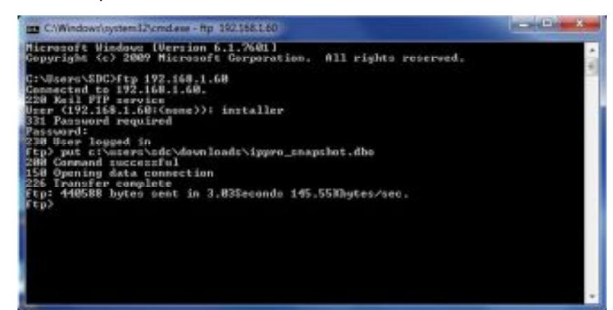
To restore using the command line FTP:
Step 1: From the command line, enter ftp followed by the IP address of the controller.
ftp 192.168.1.60
Step 2: Enter the installer username and password.
Username: installer Password: 999999
- Step 3: Copy the database to the controller. From the FTP command prompt enter put directory\filename . The directory is the PC location where the backup file is stored and the filename must be ippro_snapshot.dbo . When successful, the database is restored as a snapshot on the controller.
- Step 4: From the ftp command line, type quit. Step 5: From the command line, type exit and return to the web browser interface.
- Step 6: Login as installer .
- Step 7: From the Home screen, select " Administration " from the Menu.
- Step 8: From the Database Snapshot Tab, Click Restore Snapshot .
- Step 9: Click OK to confirm. The controller has been updated.
13.0 Features & Specifications
- Controls one door directly, with unlimited expansion capabilities
- TCP/IP communications (100/10Mbps)
- DHCP or Static IP addresses
- Password protected built-in web server (No separate software to install)
- Live transaction monitoring
- Entry & exit reader capability
- Compatible with industry standard Wiegand output readers
- Reader short circuit protection
- 1,000 users (up to 2 credentials per user). 60,000 users when using the PLUS software.
- Batch card enrollment
- 250 User groups/Time Zones/Door Groups
- Holiday support
- Scheduled Events
- Temporary Users
- Audit Trail Up to 5,000 events maybe exported as a .csv file
- Status LED's Power, Communications, & Fault on-board diagnostic indicators
- Anti-tailgating
- Supported browsers: Microsoft Internet Explorer, Firefox, Google Chrome
- Multiple credential modes: Card only, PIN only, Pin or Card, Pin & Card
- Door Status Monitoring Input
- Request-to-Exit (REX) Input
- Programmable Auxiliary Input
- Lock Relay Output
- Auxiliary Relay Output
- (2) Programmable Solid-state Outputs
- Tamper Input
- Database backup support
| / Door Station | n Expansion |
|---|---|
| Voltage | 12 VDC Input |
| Current Consumption (max) |
250mA - Controller
120mA - Door Station Expansion |
| Operating Temperature | 14°F = 122°F (Indoor use only) |
| Dimensions |
5.375" x 3.5" x 0.875" board only
9.25" x 6.5" x 2.1875" w/ ABS plastic enclosure |
| Weight | 1lb |
| Relay Output Type | Form C (SPDT) x 2 |
| Relay Contact Rating |
Main (Lock) - 5A @ 30VDC
Auxiliary - 1A @30VDC |
| Connections |
Digital Inputs: 4 dry contact inputs
Ethernet: RJ45 (Controller only) RS-485 Terminal Bus Reader Power – 12VDC Reader Data – Wiegand (26bit to 37bit) Reader LED Control – Red & Green Two Solid State outputs (100mA max) |
| Input voltage | 44 - 57 VDC | |
|---|---|---|
| Input power | 30W max | |
| Output power | 24W max | |
| Output Current | 2A @ 12V | |
| IP Pro Injector | 6454 | |
| 4/5 (*), 7/8 (-) | ||
| IP Pro Injector PoE+ Output Pin Assignment and Polarity Output Power Voltage |
4/5 (+), 7/8 (-)
55Vdc |
Addendum #1
A1.1 Assign a Static IP Address to your PC
To connect your PC or laptop directly to the IP Pro Controller, your PC must be on the same subnet as the controller. The following example will assign your PC a static IP address on the same subnet as the IP Pro Controller. The controller has a default IP address of 192.168.1.60.
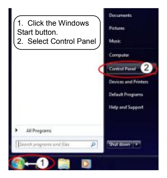
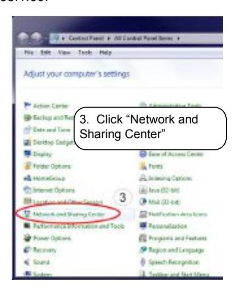
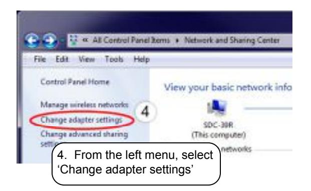
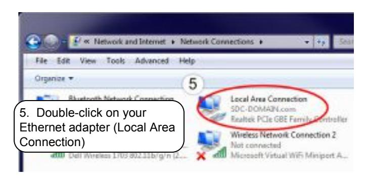

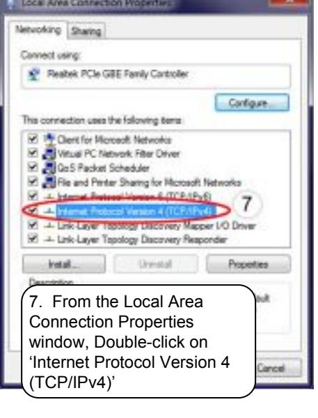
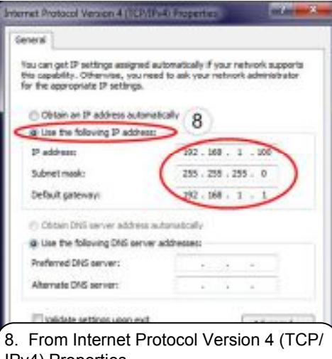
- IPv4) Properties,
- (a) select the option button next to 'Use the following IP address', then
- (b) Enter the IP address, subnet mask, and Default gateway, as shown.
- (c) Click 'OK' twice, then 'Close'.
A1.2 Test Communication to the IP Pro Controller (Ping Test)
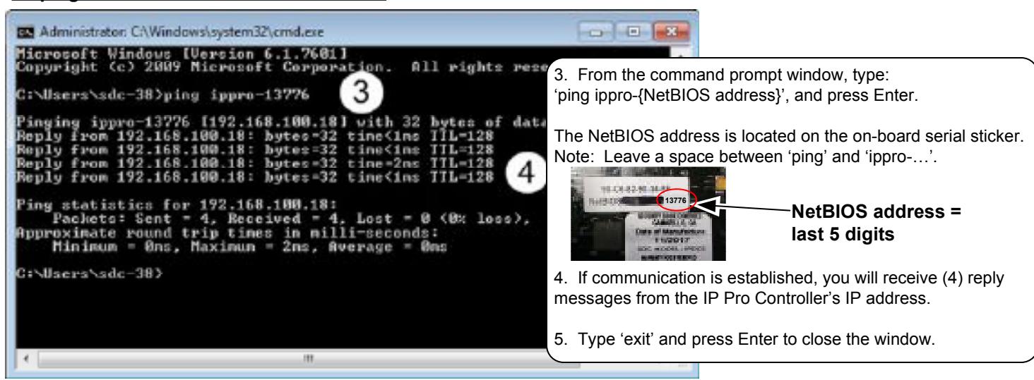
A ping test can determine whether your computer can communicate to the IP Pro Controller over the network. This is a simple test to troubleshoot your network settings. You can run the test by (a) pinging the controller's IP address or by (b) pinging the controller's NetBIOS address. Pinging the NetBIOS address is useful when the IP address is not known.
To ping the controller's IP address (Windows 7):
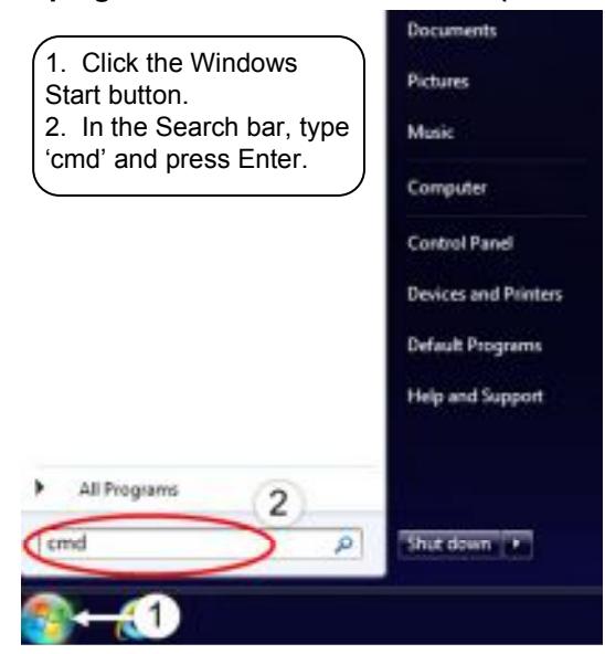
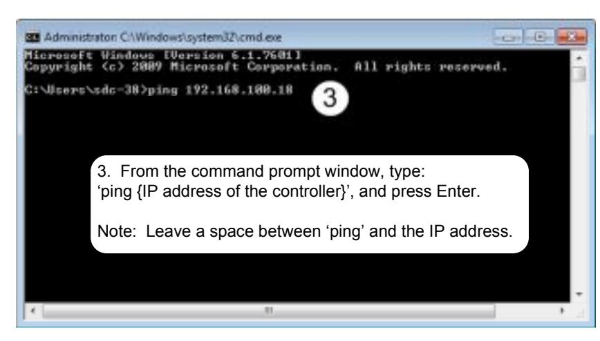
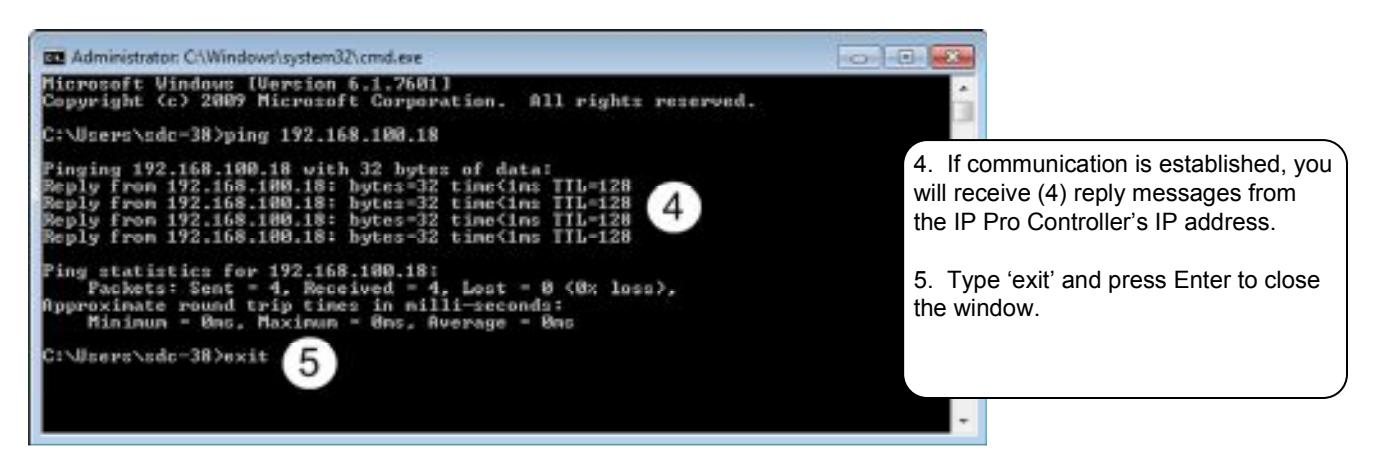
To ping the controller's NetBIOS address:
Addendum #2
A2.1 Wiring & Programming the 920PW/923PW keypad/card reader for PIN or Card Operation
For wiring instructions, follow the diagram that is included with the 920PW/923PW instruction sheet or on the SDC website.
- 1. Determine the length of PIN to be used (Default = 4 digits). If required, Use Section 11.1 on Page 18 to change the PIN length to 5 or 6 digits.
-
2. To program the system for PIN or Card operation,
- a. Log into the IPPro web server as "installer".
- b. Select "Door Settings" from the menu. Click on the blue Door Name to be configured.
- c. Click on the "Actions" tab.
- d. Use the drop-down menu next to "PIN or Card" to select "24 Hours". SAVE .
-
3. Configure the 920PW/923PW keypad to be in PIN mode by performing the following steps at the keypad:
- a. Press #9#MasterCode# {Default MasterCode = 123456. An amber LED will flash to indicated the keypad is in programming mode.
- b. Press #83#1 {The green LED will momentarily turn on, then the amber LED will begin flashing}
- c. Press **#
- 4. Log in as user and assign PIN numbers to authorized Users as required. Reference Section 8.2 on Page 14.
Addendum #3
A3.1 Port Forwarding for Remote Access
Use this procedure as a general guide to configuring your own router for remote access to the IPPro controller's web server.
Access your router's configuration interface.
In your router's port forwarding configuration, Set your external port range to 10001 to 10002.
Set your internal port to 80.
Additionally, you want the static ip address of the IPPro controller to be on the same subnet as your router. For example, if your router's local IP address is 192.168.0.1, then your controller would have the following static settings:
192.168.0.x
255.255.255.0 (mask)
192.168.0.1 (gateway)
Access remotely using router's external ip address followed by ':10001'. For example if your router's external IP address is 47.144.99.123, you will type 47.144.99.123:10001 into your browser's URL bar.