I-EA00277-Rev01
Open the original PDF document
View PDF

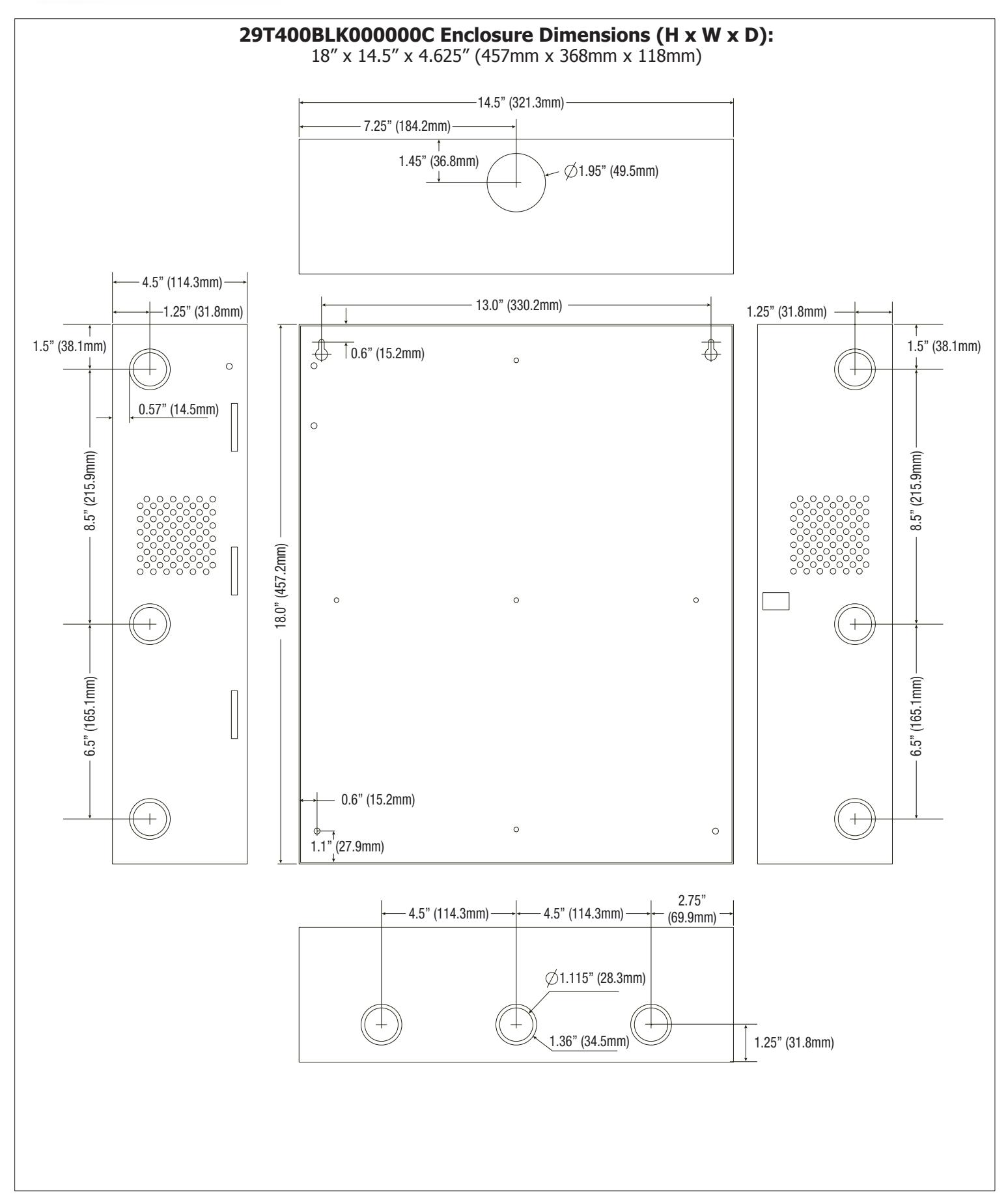
29T400BLK000000C
4 Door Kit with Fused Outputs
- Fully assembled kit includes:
- Trove1 enclosure with TSA1 Altronix/Salto backplane
- (1) AL600ULXB Power Supply/Charger
- (1) ACM4 Fused Access Power Controller
- (1) VR6 Voltage Regulator
- (1) PDS8 Dual Input Power Distribution Module
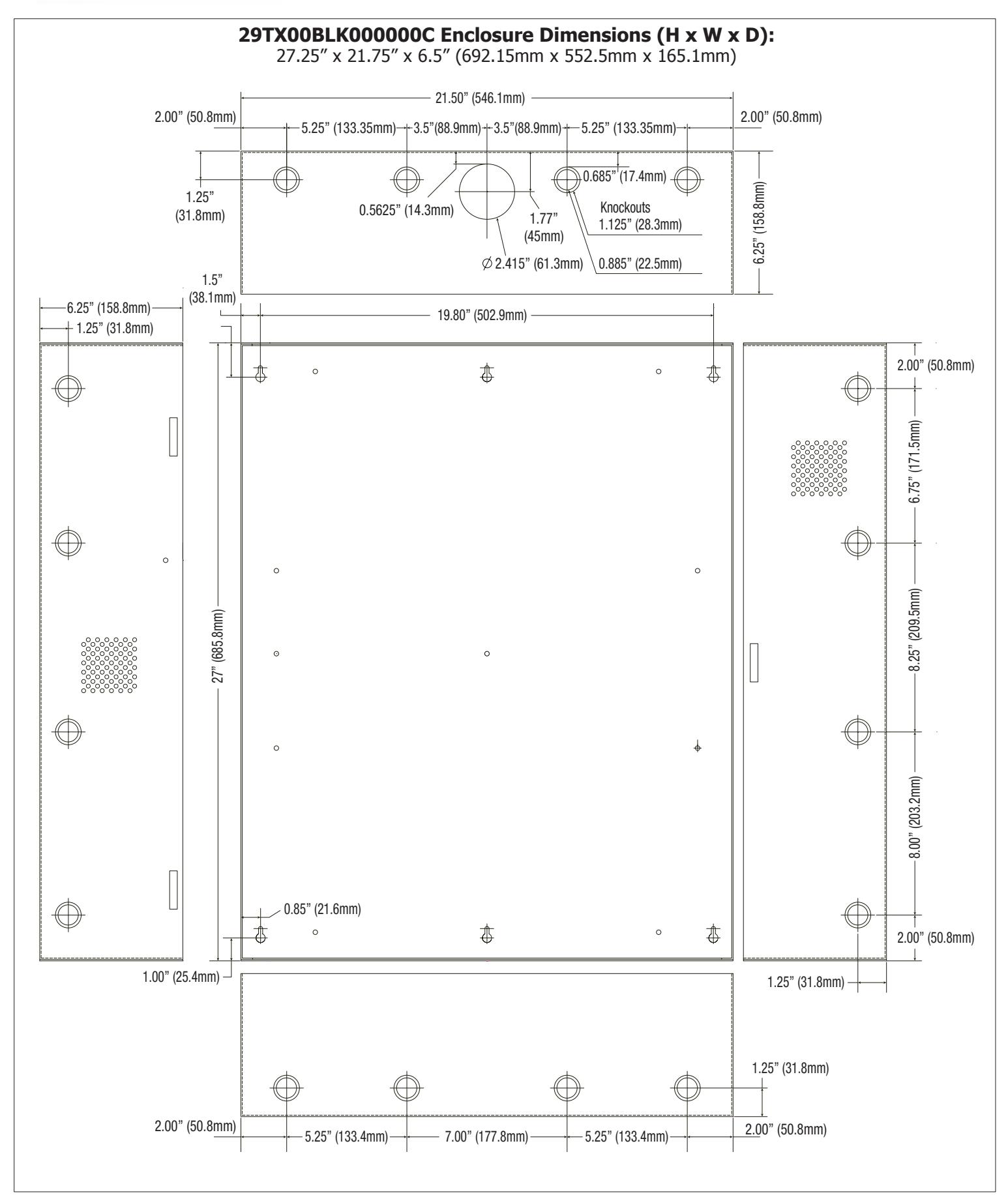
29TX00BLK000000C
12 Door Kit with Fused Outputs
Fully assembled kit includes:
- Trove2 enclosure with TSA2 Altronix/Salto backplane
- (1) AL1024ULXB2 Power Supply/Charger
- (1) AL1012ULXB Power Supply/Charger
- (1) ACM8 Fused Access Power Controller
- (1) ACM4 Fused Access Power Controller
- (1) PDS8 Dual Input Power Distribution Module
| Installing Company: Service Rep. Name: | ||
|---|---|---|
| Address: Phone #: | ||
| Rev: 1 Date: 11/03/21 |
Always visit www.hagerco.com for the latest Installation Instructions
HAGER COMPANIES 139 Victor Street, St. Louis, MO 63104 • (800) 325-9995 |
Page 1 of 8 |
Overview:
Hager kits are pre-assembled and consist of enclosure/backplane with factory installed power supply/charger(s) and sub-assemblies. These kits also accommodate various combinations of HS4 modules for up to twelve (12) doors in a single enclosure.
Configuration Chart:
|
ard
3 |
ard
ng |
Nominal DC Output Voltage | tput |
utputs
1 '9- er er |
Secure or
Outputs |
9-
ut (A) |
-6,
-0 |
-6'
ng |
70 |
d
ng |
||||
|---|---|---|---|---|---|---|---|---|---|---|---|---|---|---|
|
Hager
Model Number |
120VAC 60Hz
Input Current (A) |
Power Supply Board
Input Fuse Rating |
Power Supply Board
Battery Fuse Rating |
Power Supply 1 | Power |
Supply
2 |
Power Supply Ou | Maximum Supply Current for Main and Aux. Outp on Power Supply board and 2-679-0997, 2-679- 0998 Access Power Controller's outputs |
Fail-Safe/Fail-Sec
Dry Form "C" Oui |
997,
ard ise R |
2-679-0997, 2-679-
0998 Board Output Fuse Rating |
2-679-1000 Board
Input Fuse Rating |
2-679-1000 Board
Output Fuse Rating |
|
| 29T400BLK000000C | 3.5 | 5A/250V | N/A | 20.19-26.4 | _ | _ | - | 24VDC @ 5.6A | 4 | 2.5 |
10A/
250V |
3A/
250V |
10A/
250V |
3A/
250V |
| 29TX00BLK000000C | 6.8 | 5A/250V |
15A/
32V |
20.17-26.4 |
10.03-
13.2 |
10.03-
13.2 |
- |
12VDC @ 9.3A
24VDC @ 9.2A |
12 | 2.5 |
10A/
250V |
2.5A/
250V |
10A/
250V |
3A/
250V |
Installation Instructions Enclosure/Tamper Switch:
Wiring methods shall be in accordance with the National Electrical Code/NFPA 70/ANSI, and with all local codes and authorities having jurisdiction. Product is intended for indoor use only.
- 1. Remove backplane(s) from enclosure. Do not discard hardware.
- 2. Mark and predrill holes in the wall to line up with the top three keyholes in the enclosure. Install three upper fasteners and screws in the wall with the screw heads protruding. Place the enclosure's upper keyholes over the three upper screws, level and secure. Mark the position of the lower three holes. Remove the enclosure. Drill the lower holes and install the three fasteners. Place the enclosure's upper keyholes over the three upper screws. Install the three lower screws and make sure to tighten all screws.
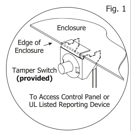
- 3. Mount included UL Listed tamper switch (Model TS112 or equivalent) in desired location, opposite hinge. Slide the tamper switch bracket onto the edge of the enclosure approximately 2" from the right side (Fig. 1, pg. 2). Connect tamper switch wiring to the Access Control Panel input or the appropriate UL Listed reporting device. To activate alarm signal open the door of the enclosure.
- 4. Mount HS4 modules to backplane, refer to Figs. 2-3, pgs. 3-4.
Hardware:
Rev: 1 Date: 11/03/21
Sylon Standoff | ( 5/16" Pan Head Screw | ( Lock Nut

29T400BLK000000C Configuration of HS4 Modules:
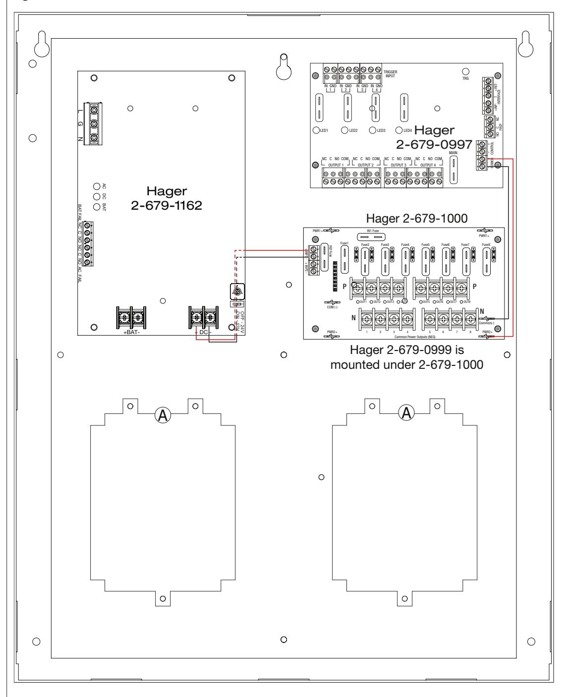
- 1. Fasten standoffs onto metal pems configuration (A) of backplane (Fig. 2, pg. 3).
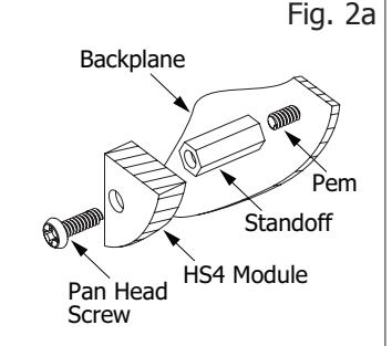
- 2. Position HS4 modules over corresponding standoffs and mount them utilizing pan head screws (provided) (Fig. 2a, pg. 3).
- 3. Mount backplane to enclosure with hardware.
Access Controller Position Chart for the Following Models:
| HS4 Access Controller | Pem Mounting | ||
|---|---|---|---|
| CU42E0, CU4200 or CU4EB8 | A | ||
Fig. 2

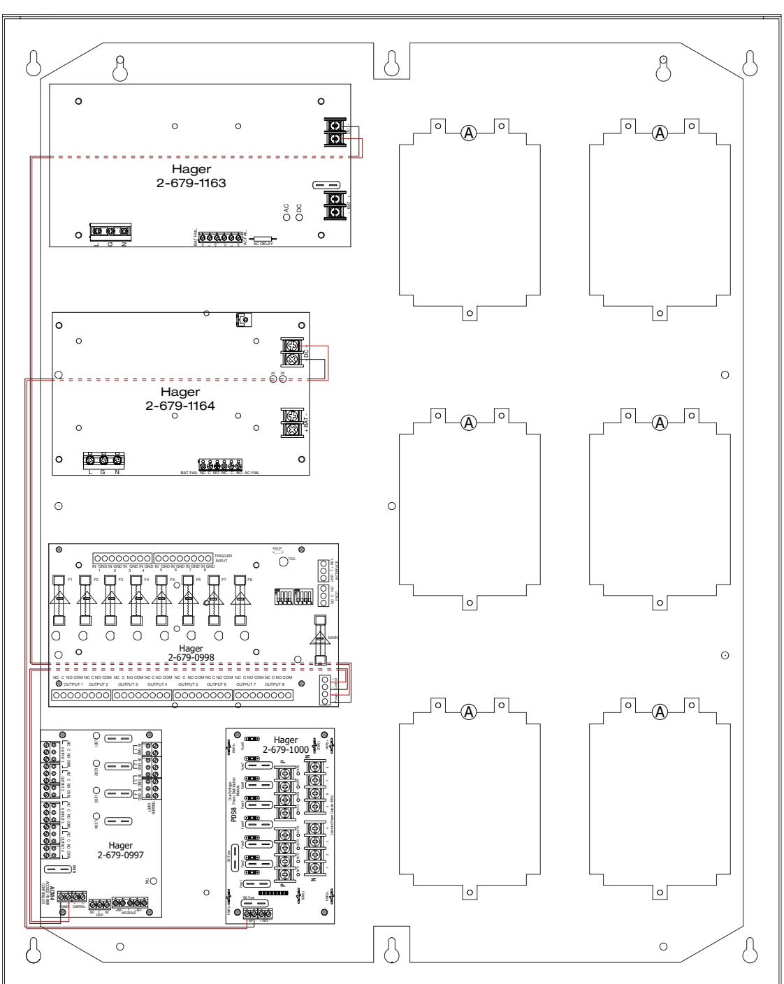
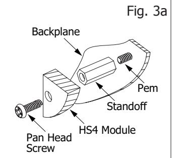
- 29TX00BLK00000C Configuration of HS4 Modules: 1. Fasten standoffs onto metal pems configuration (A) of backplane (Fig. 3, pg. 4).
- 2. Position HS4 modules over corresponding standoffs and mount them utilizing pan head screws (provided) (Fig. 3a, pg. 4).
- 3. Mount backplane to enclosure with hardware.
Access Controller Position Chart for the Following Models:
| HS4 Access Controller | Pem Mounting |
|---|---|
| CU42E0, CU4200 or CU4EB8 | A |
Fig. 3
Rev: 1 Date: 11/03/21



| Notes: |
|---|

| Notes: | |
|---|---|