I-EA00051-Rev02
Open the original PDF document
View PDF

INSTALLATION INSTRUCTIONS DELAYED EGRESS MAGLOCK 2958 / 2958T
PUSH UNTIL ALARM SOUNDS. DOOR CAN BE OPENED IN 15 SECONDS.
KEEP PUSHING. THIS DOOR WILL OPEN IN 15 SECONDS. ALARM WILL SOUND.
California Building Code Compliant
<u>Application</u>
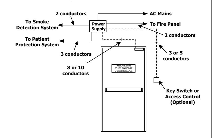
When unauthorized egress is initiated, the 2958 delays egress through the door for 15 or 30 seconds. Meanwhile, the person exiting must wait while personnel or security respond. An integral digital countdown display and voice commands inform the person intending to exit of the seconds remaining to unlock. The door unlocks after 15 or 30 seconds have elapsed, permitting egress. A signal from the fire/life safety system will release the lock for uninhibited egress in an emergency.
Applications include:
- Restricting the egress of patients for their own safety.
- Restricting the egress of commercial center patrons for security application needs.
- Controlling pedestrian traffic in transportation facilities, including airport jetways and tarmacs
Standard Features
1650 lbs. Holding Force15 or 30 Second Exit Delay when activated.1 or 2 Second Nuisance Delay75dB Alarm Tone with Digital Display & Selectable Voice Choice of Activation Trigger:
- Door Movement
- Exit Device w/ REX Switch
- Touch Sense Bar w/REX Switch
Vandal resistant Proximity Sensor Trigger Auto Sensing 12/24VDC input power
Connection for Tandem Option (Pairs of Doors)
Selectable Automatic & Manual Power-Up Feature
Auto Power-Up — Occurs when power is restored and/or the fire panel is restored.
Manual Power-Up – This is a UBC & California Building Code Compliant Feature – Only after power restoration and fire panel reset may the lock be reset manually at the opening. Lock can be reset with the built-in reset key switch or, a key switch or keypad adjacent to the door.
Optional Features
DPS Door Position SwitchMBS Bond Alert SensorATS Anti Tamper Switch
Building & Fire Life Safety Code Compliant
IBC International Building Code IFC International Fire Code NFPA 101 Life Safety Code NFPA 1, UFC, Uniform Fire Code
UBC Uniform Building Code
CBC California Building Code SBC Standard Building Code
BOCA National Building Code compliant
Chicago Building Code compliant

GWXT, GWXT7 - Auxiliary Locks - UL,cUL Listed FWAX - Special Locking Arrangements - UL Listed

California State Fire Marshal Listed CSFM #3774-0324:103

Specifications
Interior Applications Only Input Voltage Requirements:
Dual Voltage (Auto Sensing) – 12/24 VDC (+/- 10%)
(Use with a UL 294 Standard Power Supply)
Power Consumption:
Standard Model (1650 lbs.) -
2958 – 820/500 mA@ 12/24 VDC 2958T – 1500/850 mA @ 12/24 VDC
Energy Saver (1200 lbs., "E" Option) – 2958 – 452/274 mA@ 12/24 VDC 2958T – 660/686 mA @ 12/24 VDC
Size: 11"L x 2-3/4"H x 2-5/8"D
Lock Status Relay Rating: 1 Amp @ 30V resistive Alarm Output Rating: 1 Amp @ 30V resistive
DPS Rating: 250 mA @ 30V resistive BAS Rating: 250 mA @ 30V resistive ATS Rating: 1 Amp @ 30V resistive
Operating Condition: 0-49 deg C, 85% RH (non-condensing)
Inputs & Outputs
REX Input
Fire Alarm/Smoke Detection System Release
Remote Reset Input Remote Trigger Input
Tandem/Slave Lock Input
IBO – Instant Bypass Override
DPS – Door Position Status (Optional) MBS – Magnetic Bond Status (Optional)
ATS - Anti-Tamper (Optional)
Alarm Output
Lock Status Relay Output
- Door Secure
- Door Unlocked
(NFPA-101)
The 1511S operation complies with the following building and fire codes: NFPA 101; NFPA 1-UFC; UBC; IBC; IFC; SBC; CBC (California Building Code). Listings: UL Listed: Special Locking Arrangements and Auxiliary Locks; California State Fire Marshal (CSFM) Listed.
|
Option
Code |
Delay Release
Time |
Nusiance
Time |
Reset after
Alarm |
Lock Status on
Power-Up |
|||
|---|---|---|---|---|---|---|---|
| NA |
15 sec or 30 sec
Selectable |
1 sec or 2 sec
Selectable |
Manual |
Locked or Unlocked
Selectable |
|||
| ND |
15 sec
Fixed |
0 sec or 1 sec
Selectable |
Manual |
Locked or Unlocked
Selectable |
|||
| NH |
30 sec
Fixed |
0 sec or 1 sec
Selectable |
Manual |
Locked or Unlocked
Selectable |
|||
|
NC
(CBC Compliant) |
15 sec
Fixed |
0 sec or 1 sec
Selectable |
Manual |
Unlocked
Fixed |
|||
Per BOCA compliance, the Exit Check is manually reset by authorized personnel after an alarm by closing the door and actuating the integral reset key switch or by momentarily closing a contact connected to the remote reset terminals. In addition, reset will be automatically initiated once the door has been opened, then closed and remains closed for 30 consecutive seconds.
(BOCA/Chicago)
The 1511S operation complies with BOCA National Building Code and the Chicago Building Code: UL Listed, Special Locking Arrangements and Auxiliary Locks.
| Option | Delay Release | Nusiance | Reset after | Lock Status on | |||
|---|---|---|---|---|---|---|---|
| Code | Time | Time | Alarm | Power-Up | |||
| BD |
15 sec
Fixed |
0 sec or 1 sec
Selectable |
Auto/Manual |
Locked or Unlocked
Selectable |
|||
| ВН |
30 sec
Fixed |
0 sec or 1 sec
Selectable |
Auto/MAnual |
Locked or Unlocked
Selectable |
|||
| BC | 15 sec | 0 sec | Auto/Manual | Locked or Unlocked | |||
| (CHICAGO) | Fixed | Fixed | Selectable | ||||
Included in Package
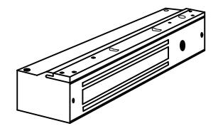
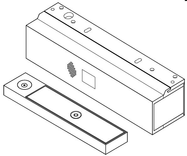
MAGLOCK HOUSING ASSY. & MOUNTING PLATE
Rev 2, Rev Date: 02/14/23
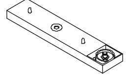
TRIGGER & ARMATURE BASE

ARMATURE
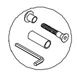
ARMATURE SCREW PACK
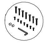
MAGLOCK SCREW PACK
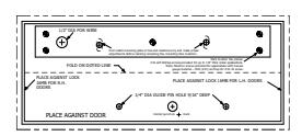
TEMPLATE

Door and Frame Preparation Instructions
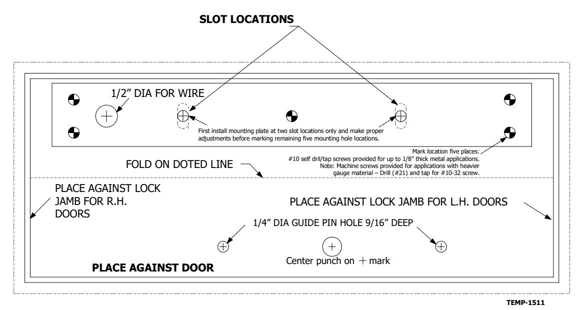
STEP 1. Locate the paper template and fold along the dotted line. Place the folded edge of the template against the door stop and door at the header while against the vertical stop, opposite the hinge side of the door. Tape in place at this position.
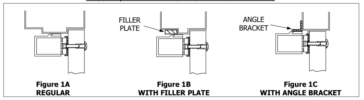
STEP 2. As indicated on the paper template, punch the designated hole locations on the frame and armature mounting holes on the door. (NOTE: PRIOR TO DRILLING, INSPECT TO SEE IF ANY OF THE HOLES CANNOT BE DRILLED DUE TO THE FRAME OR DOOR CONFIGURATION. A FILLER PLATE OR ANGLE BRACKET MAY BE REOUIRED. SEE PAGE 4.)
STEP 3. Drill and tap the two mounting holes as indicated on the paper template. (NOTE: READ NOTE ON TEMPLATE WITH REGARD TO SELECTING THE PROPER HOLE SIZE FOR ARMATURE MOUNTING BOLT.)
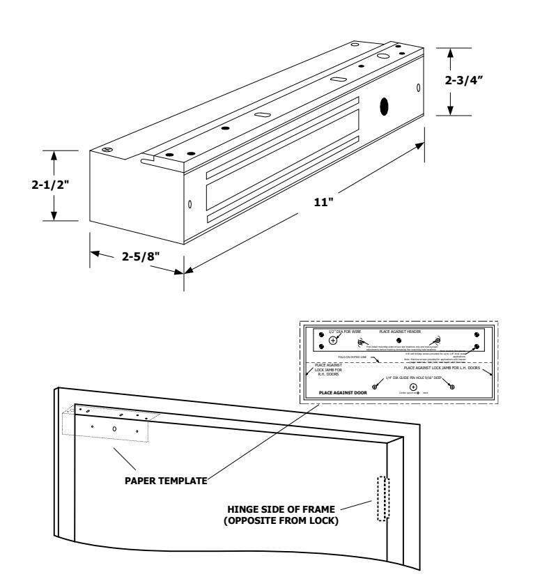
Door and Frame Reference
IMPORTANT! – IT IS HIGHLY RECOMMENDED THAT YOU FIRST INSTALL THE MOUNTING PLATE AT TWO <u>SLOT LOCATIONS</u> ONLY. THIS WILL ALLOW YOU TO MAKE PROPER ADJUSTMENTS OF THE LOCK'S POSITION PRIOR TO MARKING, DRILLING AND TAPPING THE FOUR PERMANENT MOUNTING PLATE HOLES.
<u>NOTES</u>
- #10 self drill/tap screws provided for up to 1/8" thick metal applications
- For applications with heavier gauge material, drill (#21) and tap for #10-32 machine screws.

ARMATURE MOUNTING INSTRUCTIONS
STEP 1. Mount armature to door. (See figures 2A, 2B & 2C.)
STEP 2. Install the mounting plate (filler plate and/or angle bracket if needed – see figures 1A, 1B & 1C) to header with only the two screws at the slotted hole locations at this time. Snug the screws down lightly (do not torque) so the mounting plate & lock can be repositioned later.
STEP 3. Temporarily install the lock to the mounting plate with the 1/4-20 socket head screws encased in the lock.
STEP 4. With the lock mounted, close the door so the armature holder just comes into contact with the face of the lock. If the door is not completely closed when the lock & armature touch, open the door and reposition the lock away from the door as described in step 2. (THIS IS TO PREVENT THE DOOR FROM
STEP 5. Remove the lock from the mounting plate, mark & punch all remaining screw and wiring holes. Drill & tap holes as indicated on the paper template and install all screws.
USING THE LOCK AS THE DOOR STOP.)
STEP 6. Reinstall the lock to the mounting plate. At this point, if there is no need to remove the lock for painting or any other reason, install the anti-tamper plugs over the socket head mounting screws, using a soft hammer to avoid damage to the lock case.
Rev 2, Rev Date: 02/14/23
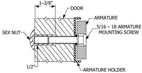
Figure 2A - SOLID DOOR
Drill exactly 3/8" diameter through the door. From sexnut side of door, drill ½" diameter hole 1-3/8" deep. Mount armature to door with hardware provided per Figure 2A.
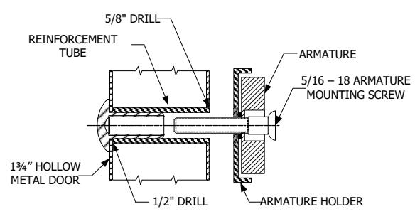
Figure 2B – HOLLOW METAL DOOR From sexnut side of door, drill exactly 1/2" hole through one metal thickness only. From armature side of door, drill 5/8" hole to insert reinforcement tube. Press in sexnut & reinforcement tube all the way and mount armature to door using hardware provided per Figure 2B.
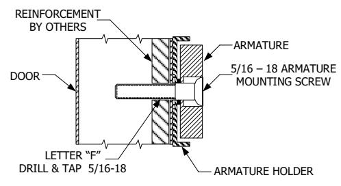
Figure 2C – REINFORCED ALUMINUM OR HOLLOW METAL DOOR
Use letter "F" drill and tap for 5/16-18 machine screw. Mount armature to door with hardware provided per Figure 2C.
REGULAR, FILLER PLATE & ANGLE BRACKET DETAILS

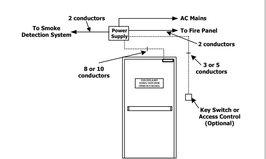
Typical System Wiring - Single Door (Model 2958)
Display Modes
15 Door armed and locked.
Alarm countdown has ended, door is unlocked and alarm sounding until reset.
Door unlocked and alarm is shunted (REX or Bypass)
Door has been opened after REX, Bypass or Alarm.
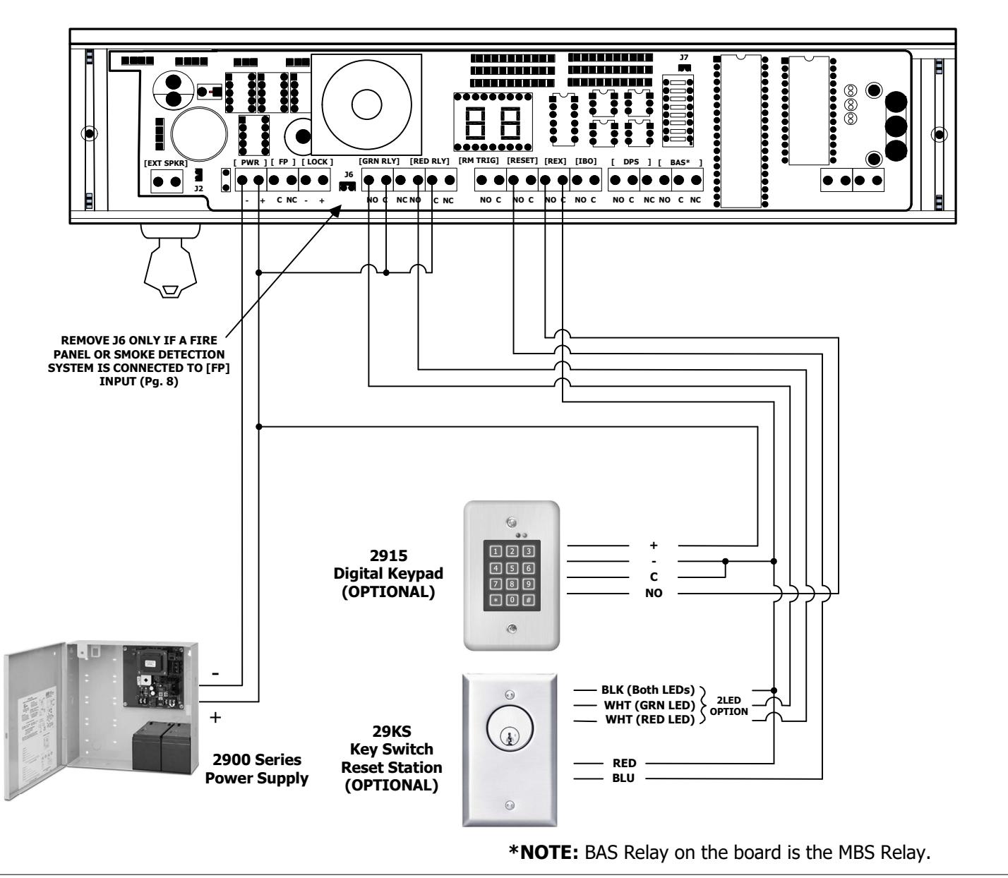

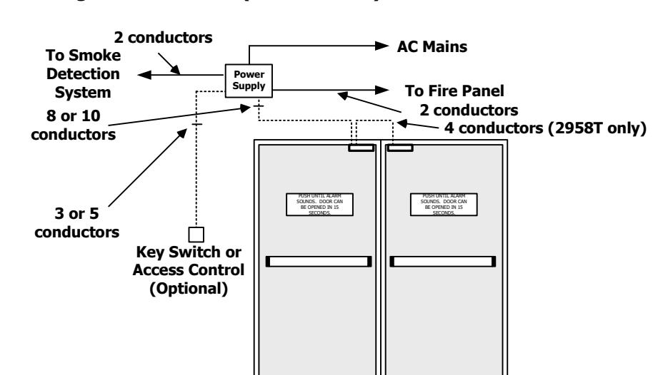
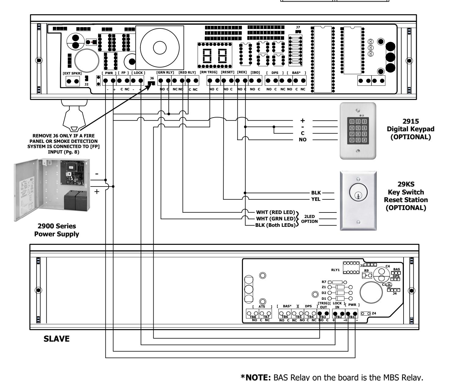
Typical System Wiring - Pair of Doors (Model 2958T)
Display Modes
- 15 Door armed and locked.
- Alarm countdown has ended, door is unlocked and alarm sounding until reset.
- Door unlocked and alarm is shunted (REX or Bypass)
- Door has been opened after REX, Bypass or Alarm.

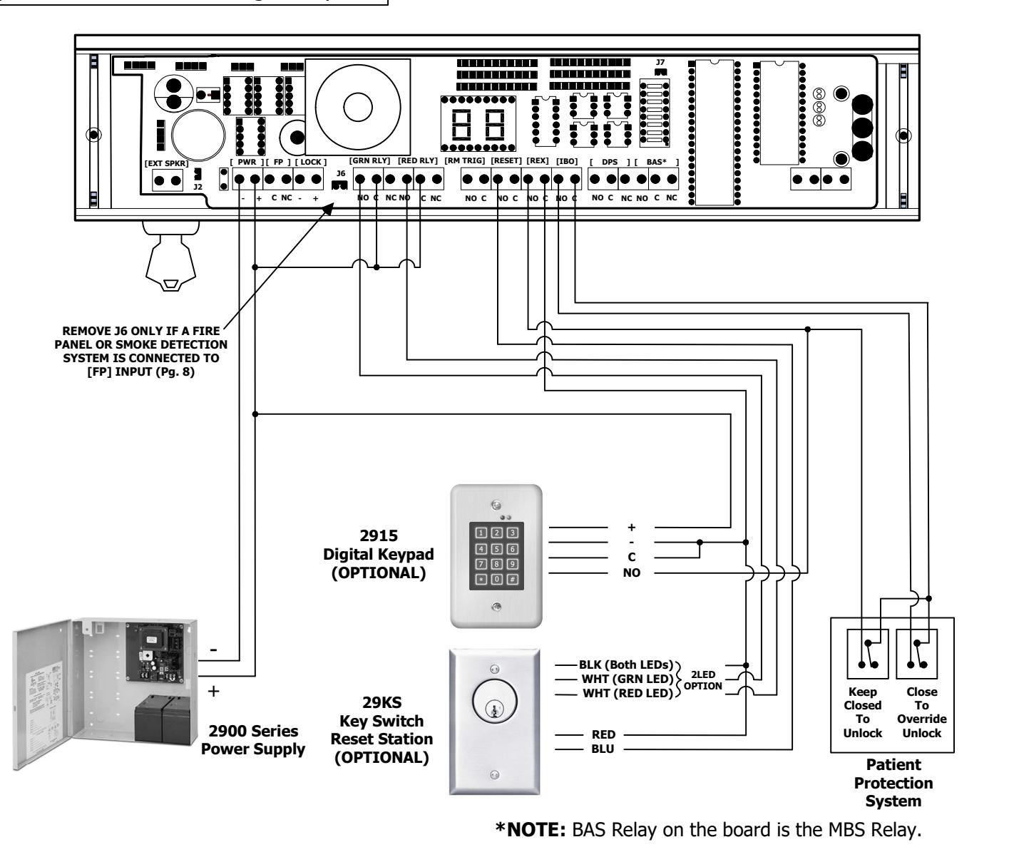
Wiring to Infant & Patient Protection Systems
System Operation
- 1. Close and hold REX input. The 2958 will be in the Bypass mode and will be unlocked.
- 2. Whenever the IBO input is closed and held, the 2958 will instantly relock and rearm. Egress is possible as the normal 15/30 sec delayed unlock.
- 3. Releasing the IBO input will return the 2958 to the Bypass mode.
- 4. Releasing the REX input will rearm the system.
- 5. Upon power-up, you must manually reset the lock to activate the IBO input.
Connection to a Infant/Patient Monitoring Systems has not been investigated by UL.

| TERMINAL BOARD CONNECTIONS | ||||||||
|---|---|---|---|---|---|---|---|---|
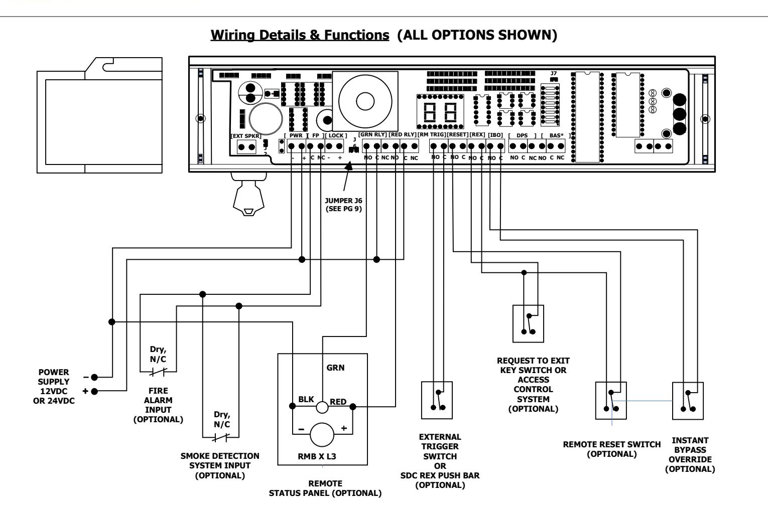
| [PWR] |
POWER IN -
POWER IN + |
12 VDC OR 24 VDC | ||||||
| [FP] |
COM
N/C |
TO CLOSED FIRE/SMOKE
DETECTOR CONTACT |
||||||
| [LOCK] |
AUX LOCK -
AUX LOCK + |
SLAVE/TANDEM LOCK
POWER TERMINALS |
||||||
| [GRN RLY] |
N/O
COM N/C |
LOCK SECURE
OUTPUT |
||||||
| [RED RLY] |
N/O
COM N/C |
ALARM OUTPUT | ||||||
| [RM TRIG] |
N/O
COM |
EXTERNAL TRIGGER
SWITCH INPUT |
||||||
| [RESET] |
N/O
COM |
EXTERNAL RESET SWITCH
INPUT |
||||||
| [REX] |
N/O
COM |
REQUEST TO EXIT
INPUT |
||||||
| [IBO] |
N/O
COM |
INSTANT BYPASS OVERRIDE
INPUT |
||||||
| MONITORI | NG OPTIONS | |
|---|---|---|
| [DPS] |
N/O
COM N/C |
DOOR POSITION
SWITCH (DPS) |
| [MBS] |
N/O
COM N/C |
MAGNETIC BOND SENSOR
(MBS) |
| [ATS] |
N/O
COM N/C |
ANTI-TAMPER SWITCH
(ATS) |
JUMPER SETTINGS
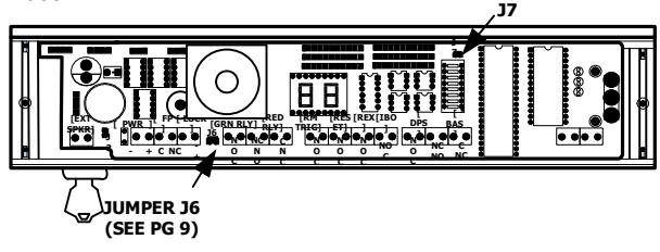
JUMPER J6 (Fire Alarm Input) – Factory Installed. Remove J6 only if a dry, normally closed contact from a fire alarm OR smoke detector system is connected to the Fire Panel [FP] terminals.
JUMPER J7 (DOOR PROP)
INSTALLED: The ExitCheck<sup>TM</sup> will enter the alarm mode if the door is held open past the request to exit period.
REMOVED: The ExitCheck<sup>TM</sup> will remain unlocked if the door is held open past the request to exit period. No alarm will sound. The ExitCheck<sup>TM</sup> will relock and rearm upon closure of the door.
*NOTE: BAS Relay on the board is the MBS Relay.

JUMPER SETTINGS
JUMPER J6 (Fire Alarm Input) – Factory Installed. Remove J6 only if a dry, normally closed contact from a fire alarm OR smoke detector system is connected to the Fire Panel [FP] terminals.
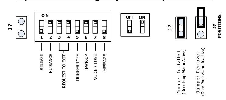
JUMPER J7 (DOOR PROP)
INSTALLED: The 2958 will enter the alarm mode if the door is held open past the request to exit period.
REMOVED: The 2958 will remain unlocked if the door is held open past the request to exit period. No alarm will sound. The 2958 will relock and rearm upon closure of the door.
DIP SWITCH SETTINGS
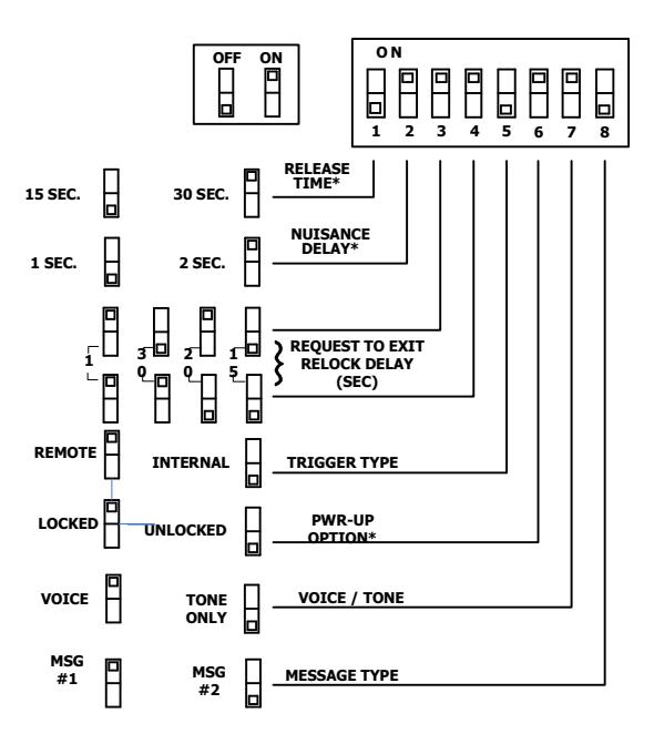
RELEASE TIME* – The Release time is selectable for 15 or 30 seconds. The Nuisance Delay time period is included in the door release cycle and it will not increase or decrease the "total time to unlock" once the MagLock is activated.
* WARNING! CONTACT AUTHORITY HAVING JURISDICTION FOR APPROVAL PRIOR TO SELECTING DELAY TIME OR PWR-UP SETTINGS
NUISANCE DELAY* – The Nuisance delay time feature, intended to avoid accidental triggering, is selectable for 1 or 2 seconds. Releasing the door latch and pushing on the door will activate the internal trigger sensor. Activating the trigger beyond the nuisance delay time will start the irreversible Exit Delay cycle time. The Nuisance Delay time period is included in the lock release cycle and it will not increase or decrease the "total time to unlock" once the 2958 is activated. Releasing the door before the end of the Nuisance delay time will turn off the warning alarm and reset the 2958 to secure mode.
REQUEST TO EXIT PERIOD – The Request to Exit (REX) time is selectable for 1, 15, 20, or 30 seconds. The REX time is the period of time the lock will remain "bypassed", after a remote normally open contact switch is momentarily activated. When activated with an access control system, the REX time cycle begins immediately after the access control open time expires. The 2958 will automatically relock if the door is opened, and then closed during the REX time cycle.
TRIGGER TYPE – The trigger type is selectable for "REMOTE" or "INTERNAL". Selecting INTERNAL mode uses the internal trigger sensor to activate the Exit Delay cycle. Selecting REMOTE mode disables the internal trigger. Activation of the Exit Delay cycle is triggered by an external exit device equipped with a normally open contact switch.
POWER-UP OPTION* – The power-up option, indicating the state of the 2958 upon restoration of system power, is selectable to "UNLOCKED" or "LOCKED". In the LOCKED mode, the 2958 will attempt to reset to secure mode. In the UNLOCKED mode, the 2958 will remain unlocked and the digital display will indicate two horizontal bars "--". Turning the reset switch momentarily to the reset position will relock and rearm the door. This feature enables the 2958 to comply with code requirements in jurisdictions that require manual reset/relock upon loss and restoration of system power.
ALARM TYPE – The alarm type is selectable to "TONE ONLY" or "VOICE". When secure, the 2958 digital display will indicate a 15 second delay time. Upon activation of the irreversible Exit Delay cycle, the digital display begins counting down to zero. In VOICE mode, the countdown will be accompanied by a warning beeping tone and verbal exit instructions. When the digital display indicates zero, the 2958 releases. The speaker output changes to a continuous warning tone and the verbal instruction announces "Exit Now". In TONE ONLY mode, the countdown will be accompanied by a warning beeping tone only, which changes to a continuous tone once the Exit Delay cycle expires.
MESSAGE TYPE - The message type is selectable to "MSG1" or "MSG2".
MSG1: (Female Voice) "Exit in 12 seconds, facility staff has been notified...Exit in 5 seconds...exit now..."
MSG2: (Male Voice) "Exit in 12 seconds, security has been alerted...Exit in 5 seconds...exit now..."
Both messages repeat "Exit now" until the lock is reset.

Dip Switch Settings By Model Option Code
|
RELEASE
TIME |
NUSIANCE
DELAY |
REQUEST TO EXIT
PERIOD |
TRIGGER
TYPE |
POWER UP
STATE |
ALARM
TYPE |
MESSAGE
TYPE |
|||||||||
|---|---|---|---|---|---|---|---|---|---|---|---|---|---|---|---|
| Option | Switch | 1 | Switch | 2 | Switches | 3 | 4 | Switch | 5 | Switch | 6 | Switch | 7 | Switch | 8 |
| NA - | 15 sec | off | 1 sec | off | 1 sec | ON | ON | Internal | off | Unlocked | off | Tone Only | off | Msg #2 | off |
| 30 sec | ON | 2 sec | ON | 15 sec | off | off | Remote | ON | Locked | ON | Tone/Voice | ON | Msg #1 | ON | |
| 20 sec | ON | off | • | ||||||||||||
| All optio | ns are select | able | 30 sec | off | ON | ||||||||||
| Option | Switch | 1 | Switch | 2 | Switches | 3 | 4 | Switch | 5 | Switch | 6 | Switch | 7 | Switch | 8 |
| 15 sec | off | 1 sec | off | 1 sec | ON | ON | Internal | off | Unlocked | off | Tone Only | off | Msg #2 | off | |
| ND | 15 sec | ON | 2 sec | ON | 15 sec | off | off | Remote | ON | Locked | ON | Tone/Voice | ON | Msg #1 | ON |
| 20 sec | ON | off | |||||||||||||
| NFPA Compliant | 30 sec | off | ON | ||||||||||||
| Option | Switch | 1 | Switch | 2 | Switches | 3 | 4 | Switch | 5 | Switch | 6 | Switch | 7 | Switch | 8 |
| 15 sec | off | 1 sec | off | 1 sec | ON | ON | Internal | off | Unlocked | off | Tone Only | off | Msg #2 | off | |
| NC | 15 sec | ON | 2 sec | ON | 15 sec | off | off | Remote | ON | Unlocked | ON | Tone/Voice | ON | Msg #1 | ON |
| NFPA/OSHPD compliant. Power Up Unlocked and | 20 sec | ON | off | 1 | l | ||||||||||
| NFPA/U |
ant. Pow
Reset are |
ea ana | 30 sec | off | ON | ||||||||||
| , | |||||||||||||||
| Option | Switch | 1 | Switch | 2 | Switches | 3 | 4 | Switch | 5 | Switch | 6 | Switch | 7 | Switch | 8 |
| BD - | 15 sec | off | 0 sec | off | 1 sec | ON | ON | Internal | off | Unlocked | off | Tone Only | off | Msg #2 | off |
| 60 | 15 sec | ON | 1 sec | ON | 15 sec | off | off | Remote | ON | Locked | ON | Tone/Voice | ON | Msg #1 | ON |
| BOCA compliant. Automatic alarm reset after 30 | 20 sec | ON | off | ||||||||||||
| C | ontinuous se | conds of | door closure | 30 sec | off | ON | |||||||||
| Option | Switch | 1 | Switch | 2 | Switches | 3 | 4 | Switch | 5 | Switch | 6 | Switch | 7 | Switch | 8 |
| D.C. | 15 sec | off | 0 sec | off | 1 sec | ON | ON | Internal | off | Unlocked | off | Tone Only | off | Msg #2 | off |
| ВС | 15 sec | ON | 0 sec | ON | 15 sec | off | off | Remote | ON | Locked | ON | Tone/Voice | ON | Msg #1 | ON |
| nuisance. Au | 20 sec | ON | off | • | |||||||||||
|
alarm reset after 30 continuous seconds of door
closure |
30 sec | off | ON | ||||||||||||
| Option | Switch | 1 | Switch | 2 | Switches | 3 | 4 | Switch | 5 | Switch | 6 | Switch | 7 | Switch | 8 |
| 30 sec | off | 0 sec | off | 1 sec | ON | ON | Internal | off | Unlocked | off | Tone Only | off | Msg #2 | off | |
| NH | 30 sec | ON | 1 sec | ON | 15 sec | off | off | Remote | ON | Locked | ON | Tone/Voice | ON | Msg #1 | ON |
| 20 sec | ON | off | |||||||||||||
| NFPA com | piiant. | 30 sec | off | ON | |||||||||||
| Option | Switch | 1 | Switch | 2 | Switches | 3 | 4 | Switch | 5 | Switch | 6 | Switch | 7 | Switch | 8 |
| 30 sec | off | 0 sec | off | 1 sec | ON | ON | Internal | off | Unlocked | off | Tone Only | off | Msg #2 | off | |
| ВН | 30 sec | ON | 1 sec | ON | 15 sec | off | off | Remote | ON | Locked | ON | Tone/Voice | ON | Msg #1 | ON |
| BOCA CO | mnliant Aut | omatic s | larm reset af | er 30 | 20 sec | ON | off | _ | |||||||
| 2227 00 | ontinuous se | a | • | ||||||||||||

Lock Adjustment and Operation
- STEP 1. After the lock has been mounted to the door and frame per the provided template, feed the wiring through the access hole and out to the controller board. Re-install the lock front cover onto the lock. Ensure that the trigger sensor is aligned with the hole in the cover. The sensor is preset at the factory to slightly project through the cover. WARNING: DO NOT ATTEMPT TO ADJUST THE TRIGGER SENSOR LENGTH. AS THIS WILL RESULT IN DAMAGE TO THE SENSOR AND VOID THE WARRANTY.
- STEP 2. Make all wiring connections to the lock. Observe the polarity of the input power terminals. The lock senses the power supply voltage and automatically configures itself for 12vdc or 24vdc operation. Correct power supply voltage must be used for proper lock operation. WARNING: INPUT TERMINALS FOR RESET, REX AND REMOTE TRIGGER MUST ONLY BE CONNECTED TO A NORMALLY OPEN MOMENTARY DRY CONTACT SWITCH (I.E. 2915 DIGITAL KEYPAD). CONNECTION TO A VOLTAGE OR A "WET" OUTPUT MAY DAMAGE THE LOCK AND VOID THE WARRANTY.
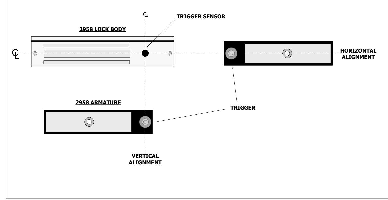
- STEP 3. Slowly swing the door closed and visually observe the position of the armature trigger as it approaches the trigger sensor on the lock. If the provided mounting template was used during the lock and armature installation, the trigger & sensor should align with one another both horizontally and vertically. The LED on the back of the trigger sensor will light when the armature trigger is detected. IMPORTANT: CORRECT OPERATION OF THIS LOCK DEPENDS ON THE TRIGGER SENSOR BEING ABLE TO DETECT THE ARMATURE TRIGGER WHEN THE DOOR IS CLOSED. A PROXIMITY ADJUSTMENT CAN BE MADE TO THE TRIGGER FOR FINE TUNING. THIS IS EXPLAINED IN STEP 4.
- STEP 4. After alignment has been verified, close the door and apply power to the lock. The digital display will show a two bars "--" indicating that the lock is in the Manual Power Up mode. Push on the door to verify that the door is unlocked. Reset the lock at this time by turning the built in key switch clockwise or by triggering the remote reset input. The lock should now secure the door and the LED display will show the delay time. You may change the mode to Auto Power Up by setting the #6 dipswitch to the ON position. Now when you first apply power, the door will be secure and the LED display will display the delay time without having to reset the lock.
- STEP 5. Activation of the 2958 can be made by door movement or an external trigger. When using the door movement method, activation is achieved through the way the armature hardware is designed. When someone unlatches the door and applies up to 15 lbs. pressure, the lock will hold onto the armature while simultaneously letting the door & trigger armature move away from the lock & trigger sensor. Sensitivity in the detection of the trigger movement can be adjusted for optimum sensitivity & performance. This adjustment can be made by using the 5mm hex wrench provided with the lock. The center of the trigger or "target" is spring loaded and can be screwed in and out of the armature thus either decreasing or increasing the space between itself and the sensor. The "spring" feature of the target is to prevent damage from direct contact with the trigger sensor. Depending on the accuracy of the alignment, the trigger does not have to physically touch the sensor to operate correctly.

Systems Applications Reference
Activation by applying pressure to doors with latching hardware:
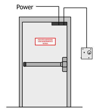
Wall Mount Reset Station (Optional)
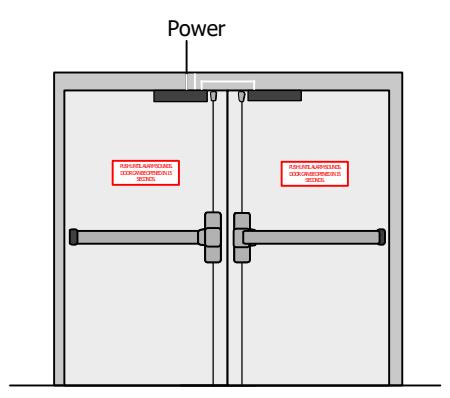
A pair of doors requires the 2958T Pushing either door triggers the delayed release of both doors
Activation by a remote trigger for doors with or without latching hardware:
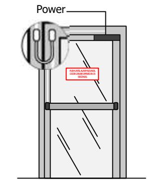
4801 Non-Latching Sense Bar Trigger
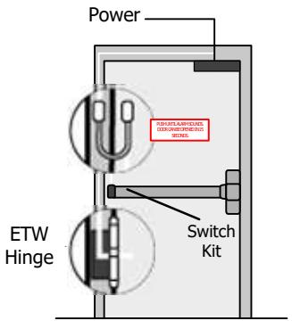
Latching Exit Device with Built-in Switch Kit Trigger