HES 8300 Series Electric Strike NFPA-80 Compliance
Open the original PDF document
View PDF

ENGINEERING EVALUATION
REPORT NUMBER: 3187773MID-002
ORIGINAL ISSUE DATE: August 28, 2009 REVISION AND DATE: Revision 1, November 15, 2010
EVALUATION CENTER
Intertek 8431 Murphy Drive Middleton, WI 53562
RENDERED TO
Hanchett Entry Systems, Inc. 22630 N. 17th Ave. Phoenix, AZ 85027
PRODUCT EVALUATED: Model 8300 electric strike UL GXAY.R9483 EVALUATION PROPERTY: Fire Resistance Email: jpeabody@hes-faedc.com
Engineering Evaluation of Hanchett Model 8300 Electric Strike for compliance with the applicable requirements of the following criteria: NFPA 80-10 Standard for Fire Doors and Other Opening Protectives
This report is for the exclusive use of Intertek's Client and is provided pursuant to the agreement between Intertek and its Client. Intertek's responsibility and liability are limited to the terms and conditions of the agreement. Intertek assumes no liability to any party, other than to the Client in accordance with the agreement, for any loss, expense or damage occasioned by the use of this report. Only the Client is authorized to copy or distribute this report and then only in its entirety. Any use of the Intertek name or one of its marks for the sale or advertisement of the tested material, product or service must first be approved in writing by Intertek. The observations and test results in this report are relevant only to the sample tested. This report by itself does not imply that the material, product, or service is or has ever been under an Intertek certification program.

1 Table of Contents
| 1 | Table of Contents | 2 |
|---|---|---|
| Introduction | ||
| Product and Assembly Description | ||
| 3.1. Product Description: | ||
| 3.2. Product Certification: | ||
| 4 | Reference Documents | 4 |
| 5 | Evaluation Method | 4 |
| 6 | Conclusion | 5 |
| 7 | Appendix | 6 |
| 8 | Last Page & Revision Summary | 7 |
2 Introduction
Intertek is conducting an engineering evaluation for Hanchett Entry Systems, Inc. on Model 8300 Electric Strike, UL Listing GXAY.R9483, to evaluate Fire Resistance. The evaluation is being conducted to determine if use in assembly to protect openings against the spread of fire and smoke will comply with NFPA 80-10 "Standard for Fire Doors and Other Opening Portectives.
3 Product and Assembly Description
3.1. Product Description:
▌
▌
▌ ▌
The 8300 series is an electric strike for use with cylindrical latches having 9/16, 5/8 or ¾ in latch bolts, when such latches are mounted in single swing doors up to 4' wide and 8' high.

See Installation Instructions in appendix
3.2. Product Certification:
Hanchett Model 8300 Electric Strike is a UL Listed Electric Strike for compliance with applicable requirements of the following standards: UL10B "Fire Tests of Door Assemblies, UL 10C "Positive Pressure Fire Tests of Door Assemblies" and UBC7-2 (1997). Model 8300 Electric Strike UL Listing GXAY.R9483 states listing for use with cylindrical latches having 9/16, 5/8 or ¾ in latch bolts. Listing information is not by Intertek and has not been confirmed by review of test data and is mentioned here for informational purposes only.
Authorities Having Jurisdiction (AHJ) should be consulted in all cases as to the particular requirements covering the installation and use of Intertek certified products, equipment, systems, devices and materials. The AHJ should be consulted before construction. Fire resistance assemblies and products are developed by the design submitter and have been investigated by Intertek for compliance with specific requirements. The published information (product and design listings) cannot always address every construction nuance encountered in the field. When field issues arise, it is recommended the first contact for assistance be the technical service staff provided by the product manufacturer noted for the design. Users of fire resistance assemblies are advised to consult the test standard referenced for each Intertek certified product. The test standard includes specifics concerning alternate materials and alternate methods of construction. Only products which bear Intertek's Mark are considered as certified. The appearance of a company's name or product in Intertek Directory of Listed Building Products does not in itself assure that products so identified have been manufactured under Intertek's Follow-Up Service. Only those products bearing the Intertek Mark should be considered to be Listed and covered under Intertek's Follow-Up Service. Always verify the Mark on the product before using it.
4 Reference Documents
As part of this evaluation, Intertek has directly or indirectly used the following referenced documents:
- UL Directory of Listed products, summary information GXAY.R9483
- NFPA 80 (2010) "Standard for Fire Doors and Other Opening Protectives"
- HES 8000/8300 Series Electric Strike Installation Instructions
- One Sample of Model 8300 Strike supplied by Hanchett Entry Systems, Inc.
5 Evaluation Method
▌
This evaluation is being conducted solely for the above italicized referenced project or use or both. Due to the variables that exist from project to project and the fact that each evaluation requires review of the most current existing data and information, this evaluation is not to be used as justification for any other opinion nor used for any other project, without the express written consent of Intertek. This report should serve as Intertek's opinion regarding the use of the certified product in the conditions described herein. The materials used on the project, which are applied in compliance with Intertek Design Listings, must bear the Intertek listing mark. All certified products must be installed in accordance with the details contained in Intertek's Directory of Listed Building Products .
The product assembly and use was evaluated against requirements in NFPA 80 that would make the use of HES Model 8300 Strike non-compliant with NFPA 80.
A review of NFPA 80 finds:
- Electric strikes are defined as strikes that, when activated, either releases or retains a projected latch or dead bolt.
- Strike plates are defined as wear plates for projecting hardware or a wear plate and keeper for a latch bolt.
- Per Section 6.4.4.11 electric strikes are permitted in lieu of conventional strikes in single swinging doors and pairs of doors where provided for in the published listings. Typical electric strikes are illustrated in annex A. figure A.6.4.4.11.

- Section 6.4.4.8 requires Strike plates are secure to frame with steel screws or other types of screws as indicated by the manufacturer's published listing or label service procedure.
- Section 6.4.4.9 requires Strike plates for doors swinging in pairs to be secured to reinforcements in the inactive leaf with machine screws and that pilot holes are predrilled per manufacturer's instructions.
An examination of the product and UL listed use found that HEC Model 8300 falls within the definition of electric strikes and complies with the above NFPA 80 criteria.
6 Conclusion
Intertek has conducted this engineering evaluation for Hanchett Entry Systems, Inc., on Model 8300 Electric Strike, UL Listing GXAY.R9483, to evaluate fire resistance. The evaluation was conducted to determine if use in assembly to protect openings against the spread of fire and smoke will comply with NFPA 80-10 "Standard for Fire Doors and Other Opening Protectives.
Based on the information contained and referenced herein, it is Intertek's professional judgment based on sound engineering principles that the following is true: UL GXAY.R9483 listed use of Model 8300 Electric Strike complies with NFPA 80-10
INTERTEK
▌
▌
Reported by:
John Schachtner
Project Engineer, Engineering Services
Reviewed by: _____________________
Mike Puls
Senior Project Engineer, Engineering Services
7 APPENDIX
HES 8000/8300 Installation Instructions
8 LAST PAGE & REVISION SUMMARY
| DATE | SUMMARY |
|---|---|
| August 31, 2009 | Original |
| November 15, 2010 |
Update to NFPA 80-2010 and to updated for consistency with UL Listing
GXAY.R9483 that no longer includes reference to Mortise |
Installation Instructions 8000/8300 Series Electric Strike
HES, Inc. 22630 N. 17th Ave. Phoenix, AZ 85027 800-626-7590 www.hesinnovations.com
1
Product Components
- ① 8000/8300 Electric Strike Body
- ② Sticky Shims (optional use)
- ③ Faceplate (sold separately)
- 4 #12-24 Mounting Screws (included with faceplate)
- (1) #8-32 Faceplate Screws (included with faceplate)
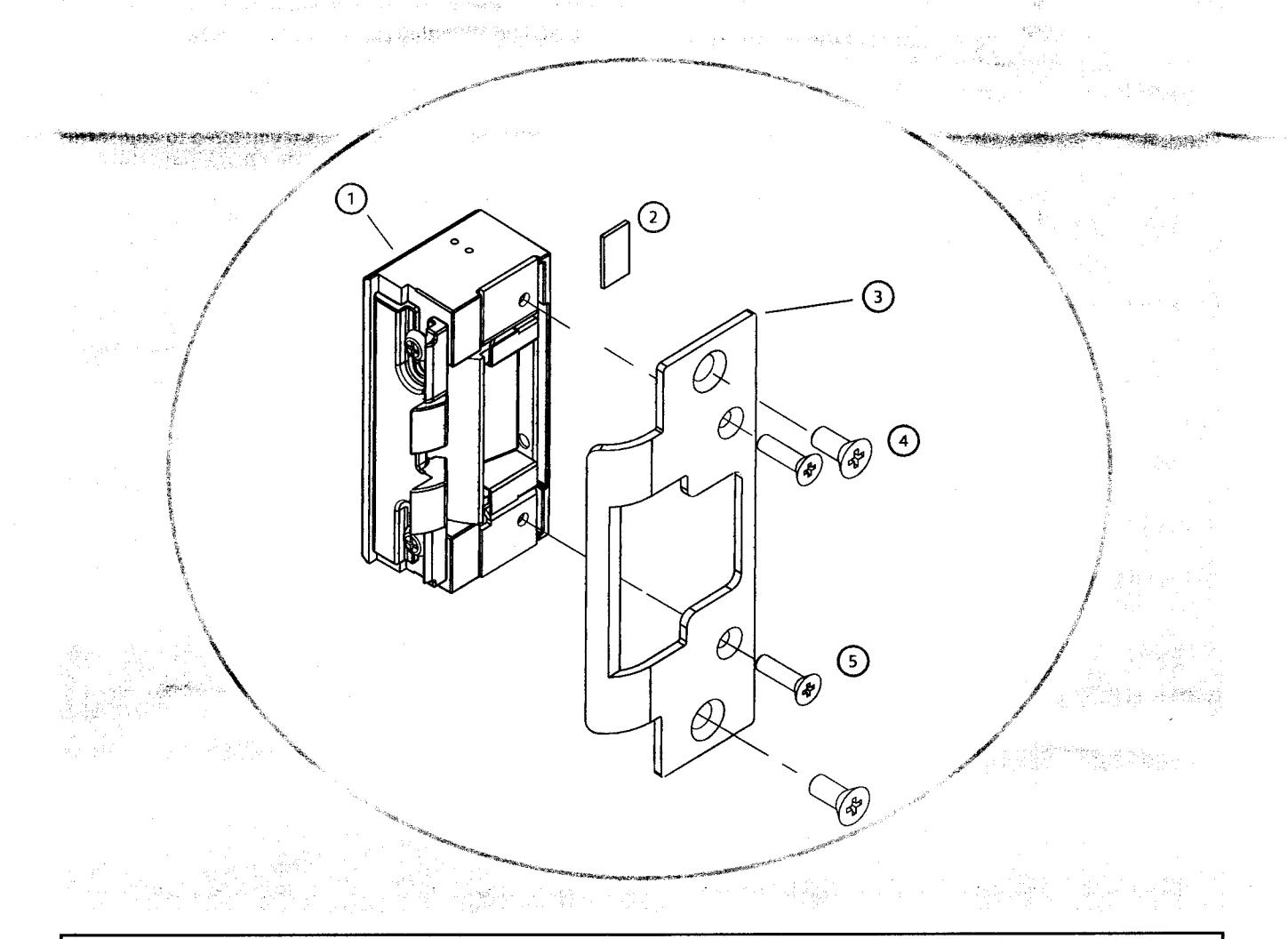
Diagram 1: Electrical Specifications
| ELECTRICAL RATINGS FOR SOLENOID | CONTINUOUS DUTY | INTERMITTENT DUTY* | ||
|---|---|---|---|---|
| 12VDC | 24VDC | 12-16VAC | 24VAC | |
| Resistance in Ohms | 50 | 200 | 50 | 200 |
| Amps | .24 | .12 | .24 | .12 |
Solenoids are rated at +/- 10% indicated value. *10% max duty cycle (2 min. max on time)
| MINIMUM WIRE GAUGE REQUIREMENTS | SOLENOID VOLTAGE | |
|---|---|---|
| 12VDC | 24VDC | |
| 200 feet or less | 18 gauge | 20 gauge |
| 200 - 300 feet | 16 gauge | 18 gauge |
| 300 - 400 feet | 14 gauge | 16 gauge |
CAUTION! Before connecting any device at the installation site, verify input voltage using a multimeter. Many power supplies and low voltage transformers operate at higher levels than listed. Any input voltage exceeding 10% of the solenoid rating may cause severe damage to the unit and will void the warranty.
Evaluate Opening
1. Verify opening is plumb and square. For important detail, see "Read Me" guide.
Prepare Strike
- Check power source and make sure that the electric strike is configured to the appropriate voltage. This electric strike ships as 12V. If you need to convert the unit from 12V to 24V, see Diagram 2.
- 3. Make sure that the electric strike is in correct mode of operation. This electric strike ships in fail secure mode. If you need to convert the unit to fail safe, see Diagram 3 on page 3.
- 4. If using Latchbolt Monitor (LBM), see Diagram 4.
- 5. Attach the faceplate to the electric strike, using the #8-32 screws provided. Be sure that the ramps are on top of the faceplate. (see Diagram 5 on page 3).
Prepare Frame
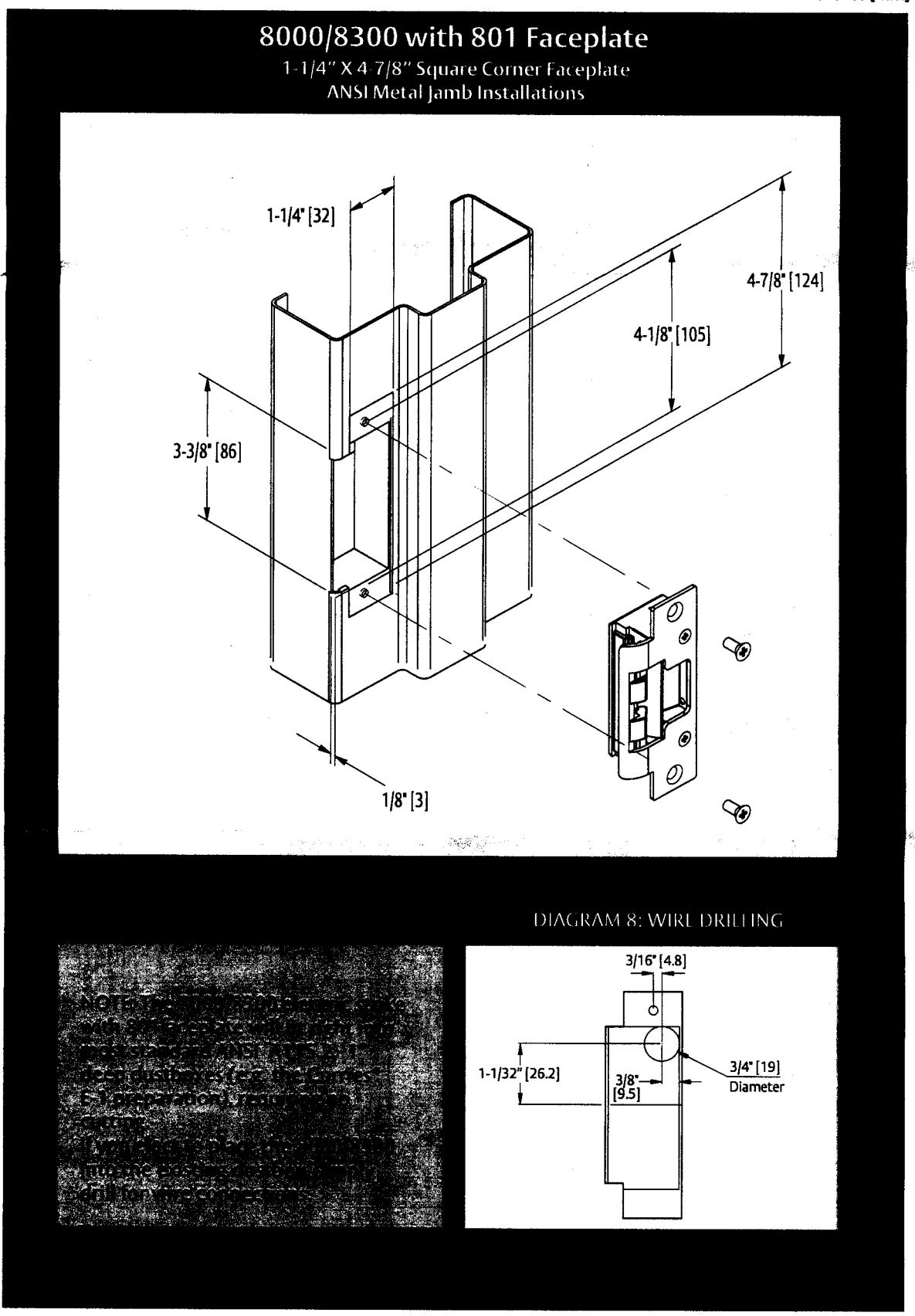
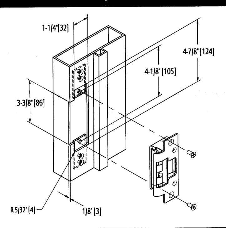
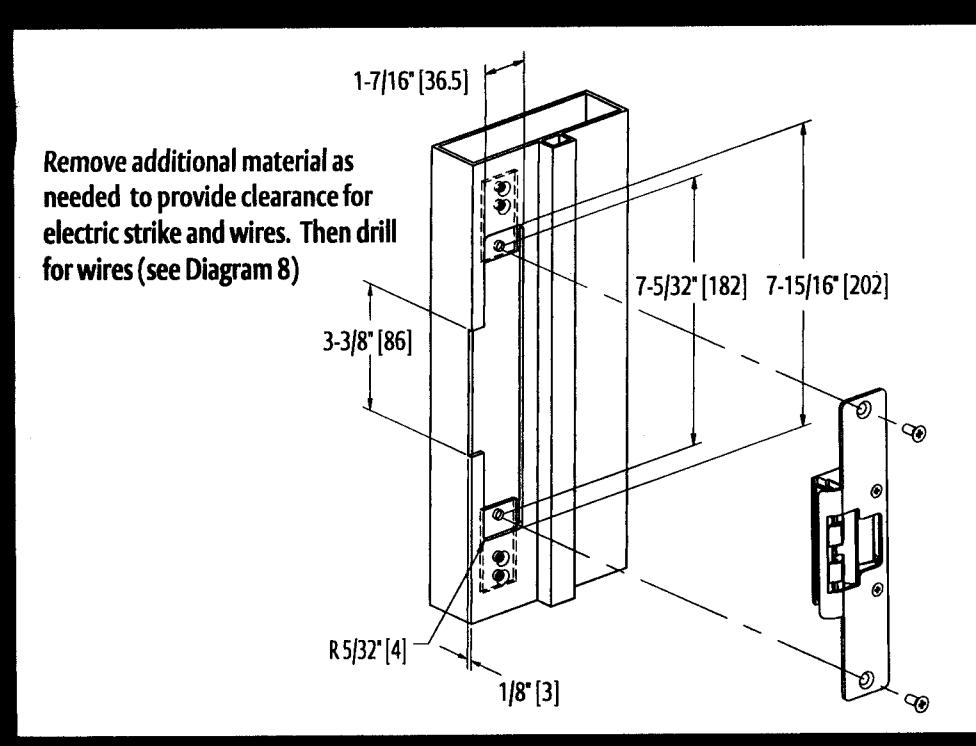
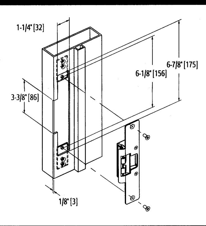
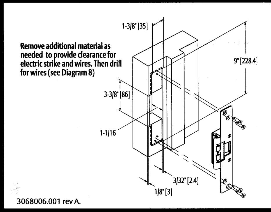
- 6. Prepare door jamb per the appropriate template detail (see pages 4-6).
- 7. If applicable, install mounting tabs using #10-32 screws. Do not tighten.
Finish Installing
- 8. If opening is not plumb and square, see "Read Me" guide for recommended corrections.
- 9. Install the electric strike unit in jamb cutout, using #12-24 screws provided (or wood screws where necessary).
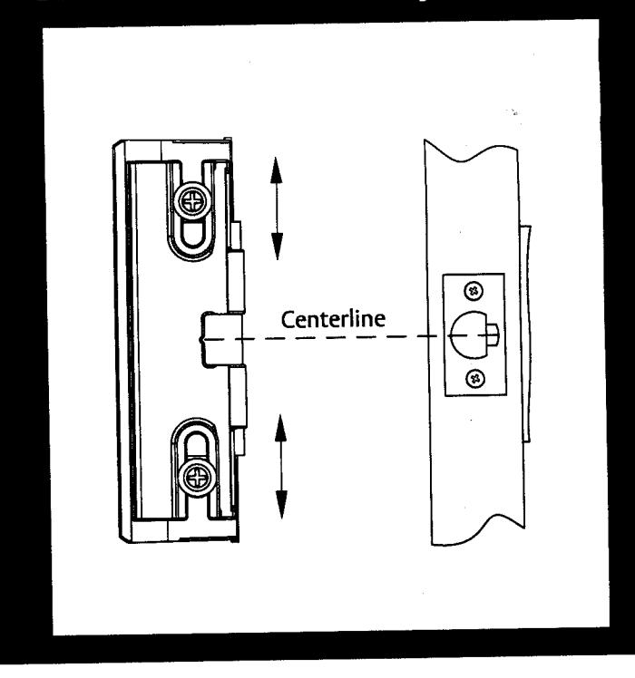
- 10. The deadlatch must not interfere with the 8000/8300 ramps (see Diagram 6 on page 3). If you need to adjust the ramps, mark the centerline of the deadlatch onto the 8000/8300 faceplate. Remove the 8000/8300 electric strike from jamb. Loosen screws and slide internal ramp until the groove between the ramps aligns with the mark made on the faceplate. Tighten the screws. (see Diagram 7 on page 3).
- 11. Connect wires from power source to the electric strike.
- 12. Reinstall electric strike, tighten the #12-24 screws and verify clearance of deadlatch.
- 13. If applicable, tighten the #10-32 screws holding the mounting tabs.
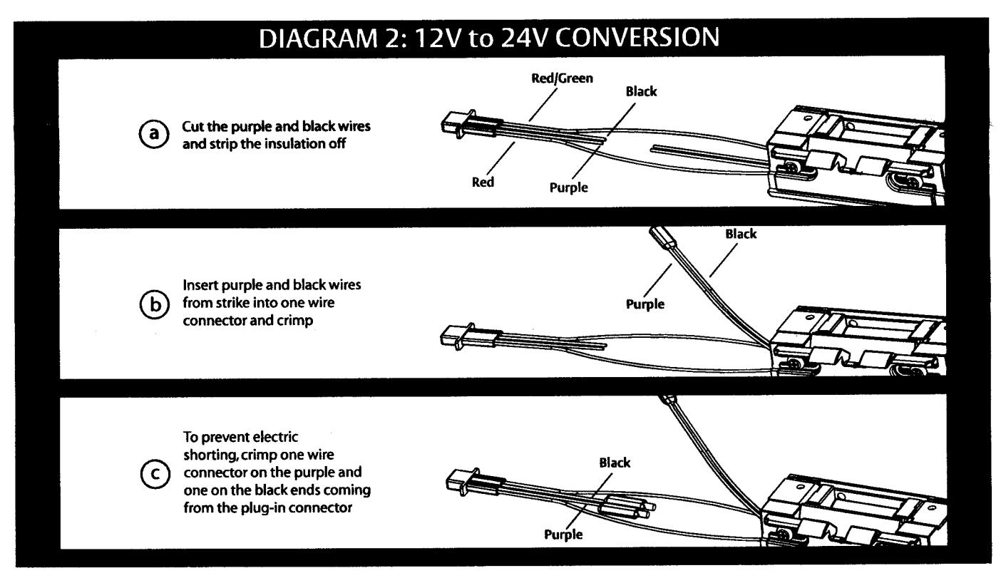
DIAGRAM 3: FAIL SAFE TO FAIL SECURE
Fail Safe*
- a Loosen screws, but do not remove them
- (b) Move screws from bottom of hole to fail safe position
- (c) Tighten screws
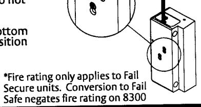
DIAGRAM 4: LATCHBOLT MONITOR
| White Common Orange Normally Open Green Normally Closed | LBM WIRING | ||
|---|---|---|---|
| White | Common | ||
| Green Normally Closed | Orange | Normally Open | , |
| Green | Normally Closed | , | |
DIAGRAM 5: FACEPLATE INSTALLATION
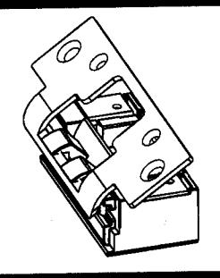
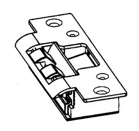
DIAGRAM 6: VERTICAL ALIGNMENT
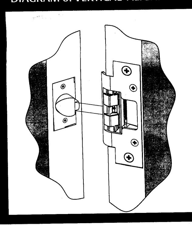
DIAGRAM 7: VERTICAL ADJUSTABILITY
Inches [mm]
Inches [mm]
8000/8300 with 801A Faceplate
1-1/4" x 4-7/8" Radius Corner Faceplate Aluminum Jamb Installations
8000/8300 with 802 Faceplate
1-7/16" x 7-15/16" Radius Corner Faceplate Aluminum and Wood Jamb Installations
Inches [mm]
8000/8300 with 803 Faceplate
1-1/4" x 6-7/8" Radius Corner Faceplate Aluminum Jamb Installations
8000/8300 with 805 Faceplate
1-3/8" x 9" Radius Corner Faceplate Aluminum or Wood Jamb Installations
© 2009 HES, Inc.

TROUBLE SHOOTING TIPS 8000/8300 SERIES ELECTRIC STRIKE
HES, Inc. 22630 N. 17th Ave Phoenix, AZ 85027 800-626-7590 www.hesinnovations.com
NOTE: The 8000/8300 electric strike requires that the opening be plumb and squareto insure proper satch
EVALUATE OPENING
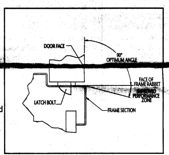
Although the design of the 8000/8300 provides adjustability to compensate for frame and door irregularities, in some cases, adjust ing the frame and door back to industry standards is just not an option. Here are some tips to quickly the frame twist and to determine the condition of the latch bolt.
One way to measure frame twist is to place a carpenter square on the stop and the face of the door. If the angle is less than 90 degrees, the 45 degree ramp angle of the 8000/8300 is steepened and may need to be corrected as shown at right.
We also recommend you check the condition of the latch bolt prior to installing the 8000/8300. Poorly constructed, worn out or damaged latch bolts may not slide along a ramp at any angle. To check the condition of your latch bolt, we recommend applying a slight force to the tip of the latch bolt (about 45 degrees to door face). Make sure the latch bolt can be pushed up into the door.

When a frame is twisted, the relationship between the face of a closed door and of the inside face of the frame (i.e. Rabbet) may not meet the 90 degree industry standard. Untrue frames and doors impact latch bolt wear and the force required to exit, so we recommend you ensure that the angle is between degrees.
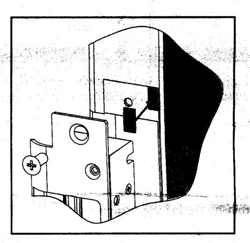
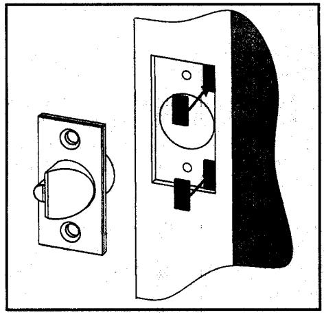
If manipulating the frame is not possible, we recommend placing several shims under the top and bottom (stop side) of the faceplate (Image right). This effectively increases the 8000/8300 ramp angle and compensates for frame twist. This can also be performed by placing shims under the top and bottom (bevel side) of the latchbolt (Image below right).

READ ME
8000/8300 SERIES ELECTRIC STRIKE
HES, Inc. 22630 N. 17th Ave Phoenix, AZ 85027 800-626-7590 www.hesinnovations.com
- Marian District Country of the American Country of the Country of the Country of the Country of the Country of the Country of the Country of the Country of the Country of the Country of the Country of the Country of the Country of the Country of the Country of the Country of the Country of the Country of the Country of the Country of the Country of the Country of the Country of the Country of the Country of the Country of the Country of the Country of the Country of the Country of the Country of the Country of the Country of the Country of the Country of the Country of the Country of the Country of the Country of the Country of the Country of the Country of the Country of the Country of the Country of the Country of the Country of the Country of the Country of the Country of the Country of the Country of the Country of the Country of the Country of the Country of the Country of the Country of the Country of the Country of the Country of the Country of the Country of the Country of the Country of the Country of the Country of the Country of the Country of the Country of the Country of the Country of the Country of the Country of the Country of the Country of the Country of the Country of the Country of the Country of the Country of the Country of the Country of the Country of the Country of the Country of the Country of the Country of the Country of the Country of the Country of the Country of the Country of the Country of the Country of the Country of the Country of the Country of the Country of the Country of the Country of the Country of the Country of the Country of the Country of the Country of the Country of the Country of the Country of the Country of the Country of the Country of the Country of the Country of the Country of the Country of the Country of the Country of the Country of the Country of the Country of the Country of the Country of the Country of the Country of the Country of the Country of the Country of the Country of the Country of the Country of the Country of the Country of the Country o
A NEW KIND OF ELECTRIC STRIKE
A standard electric strike requires a cutout on the side of the door frame to allow the extended latchbolt to exit the frame. In contrast, the 8000/8300 is designed to utilize special internal ramps to eject the latchbolt from an unmodified frame. For the 8000/8300 to operate correctly, it is important for you to first understand the relationship between the unit's internal ramps and the position of the latchbolt.
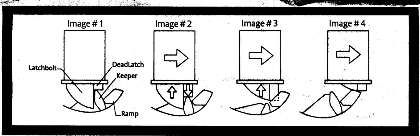
- 1. Initially, the 8000/8300 operates very much like a standard electric strike. With the door in the closed position, the latchbolt held secure by the 8000/8300's keeper (Image 1).
- 2. When energized, the keeper releases the latchbolt and as the door moves forward the deadlatch begins to drop (Image 2).
- 3. As the door continues to move forward the deadlatch and latchbolt will become fully released. The latchbolt will then pass from the keeper and begin to slide up the internal ramps (Image 3). Note: It is important that the deadlatch pass between the two internal ramps without contacting either ramp. The ramp adjustment is explained in detail within installation instructions.
- 4. As the door continues to open, the latchbolt and deadlatch will continue to slide up the internal ramps and out of the door frame to release the door. (Image 4)
WHY ANGLES ARE IMPORTANT
The 8000/8300 ramps are designed with critical angles that minimize both latchbolt wear and the force required for exit. For optimum performance, the latchbolt should be positioned at a 40 to 45 degree angle in relation to the ramps of the 8000/8300. An angle more than 45 degrees will steepen the ramp and impact the performance of the 8000/8300 (Image 5).
We understand that correctly measuring this angle in the field may be difficult. The next section is designed to help you understand some simple techniques to evaluate the condition and relationships between the door, the latchbolt, the frame and the 8000/8300.
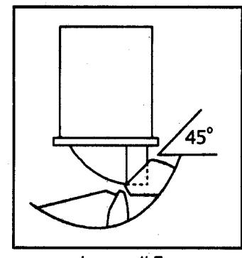
Image #5