Glynn Johnson SensaGuard 280 Series Installation Instructions 101338
Open the original PDF document
View PDF

SensaGuard™ 280 GLYNN-JOHNSON.
829416-00
Installation Instructions
PUSH SIDE – Header Mounting
Instructions:
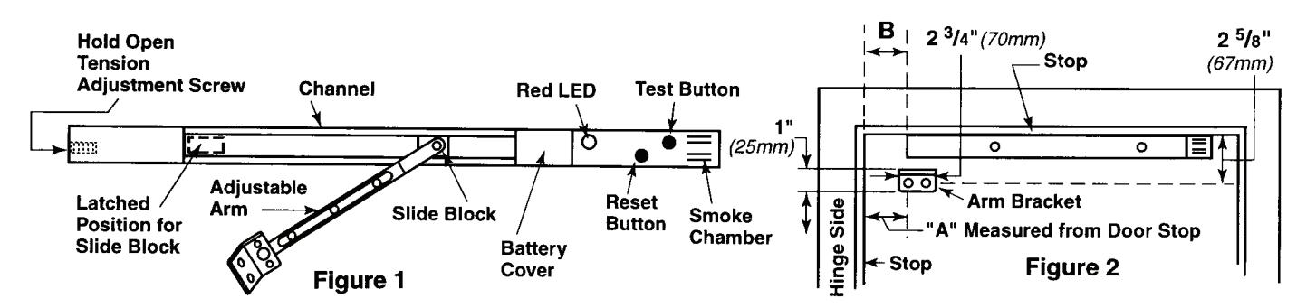
- Remove battery compartment cover (see Fig. 1) and install alkaline 9-volt battery. (The red LED should now flash once every second and the motor will run briefly.)
- Reinstall the battery cover and attach with both screws. (The red LED should stop flashing 3 seconds after securing 2nd screw.) (The red LED will now begin flashing once every 40 seconds.)
- 3. Wait 15 seconds.
- Press and hold the "reset" button for 2 seconds. (You should hear the motor run briefly.) (Note: If you do not hear the motor run, wait 15 seconds, and try again.)
- 5. Select proper "B" dimension from Table 1.
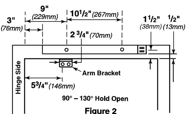
- 6. Close the door and place unit against bottom of stop (see Fig. 2).
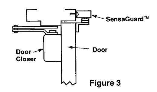
- 7. Leave a 1/8" gap between the door and the unit (see Fig. 3).
- 8. Using the unit as a template, mark the location of the 3 mounting holes in the stop.
- 9. Drill the 3 mounting holes with a 13/64" bit and tap 1/4-20.
- 10. Install the unit onto the stop with the 3 machine screws and lock washers.
- 11. Select proper "A" dimension from Table 1.
- 12. Mark the bracket hole locations on the door (see Fig. 2).
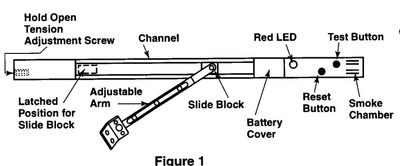
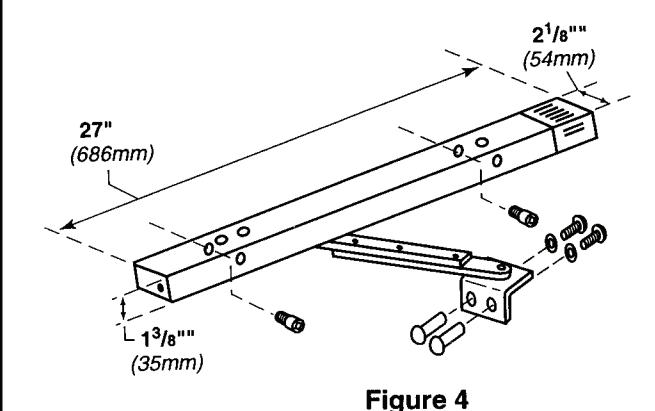
- 13. Loosen arm set screws (see Fig. 4).
- 14. For 180 degrees hold open, move the arm to the bracket hole closest to the hinge. Otherwise, leave arm in center bracket hole. Install arm bracket using sex bolts, lock washers, and sex nuts (see Fig. 4).
- 15. Move the slide block to the latched position (see Fig. 1).
- 16. Open the door to the desired hold open angle.
- 17. Tighten arm set screws (see Fig. 4). (The door should now be held open.)
- 18. Manually open and close the door several times to check the hold open position.
- 19. Manually move the door into hold open position.
- 20. Press the "Test" button to simulate a fire condition. (Door should release from hold open.)
- 21. Wait 15 seconds.
- 22. Press the "Reset" button to reset the unit.
- 23. Manually move the door into the hold open position. (Door should now be held open.)
- 24. If desired, adjust hold open tension by turning adjustment screw clockwise to increase or counterclockwise to decrease (see Fig. 1).
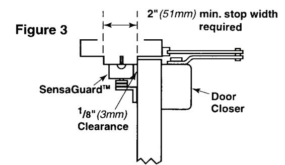
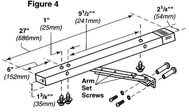
Table 1
|
Degrees
Hold Open |
90°-130° | 130° - 180° |
|---|---|---|
| Α |
4½"
(114mm) |
½"
(13mm) |
| В |
5"
(127mm) |
3"
(76mm) |
| Screw Details | ||||
|---|---|---|---|---|
| Qty. | Description | |||
| Push Side Channel | 3 | 1/4-20 x 1/2" PHMS | ||
| 3 | 1/4" Split Lock Washer | |||
| Pull Side Channel | 2 | 1/4-20 x 1/2" SHCS | ||
| Arm Bracket® | 2 | 1/4-20 x 3/3" Truss PHMS | ||
| 2 | 1/4-20 Sex Bolts | |||
| 2 | 1/4" Split Lock Washer | |||
| Channel Hole Plugs | 4 | Painted Plastic Hole Plugs | ||
* The screw comes installed in sex bolt.
PULL SIDE – Face Mounting
Instructions:
- Remove battery compartment cover (see Fig. 1) and install alkaline 9-volt battery. (The red LED should now flash once every second and the motor will run briefly.)
- Reinstall the battery cover and attach with both screws. (The red LED should stop flashing 3 seconds after securing 2nd screw.) (The red LED will now begin flashing once every 40 seconds.)
- 3. Wait 15 seconds.
- Press and hold the "reset" button for 2 seconds. (You should hear the motor run briefly.) (Note: If you do not hear the motor run, wait 15 seconds, and try again.)
- 5. Place unit against frame (see Fig. 2 & Fig. 3).
- Using the unit as a template, mark the location of the 2 channel mounting holes.
- 7. Drill the 2 mounting holes with a 13/64" bit and tap 1/4-20.
- 8. Install the unit onto the frame with the 2 socket head cap screws.
- 9. Mark the bracket hole locations on the door (see Fig. 2).
- 10. Loosen arm set screws (see Fig. 4).
- 11. Install arm bracket using sex bolts, lock washers, and sex nuts (see Fig. 4).
- 12. Move the slide block to the latched position (see Fig. 1).
- 13. Open the door to the desired hold open angle.
- 14. Tighten arm set screws (see Fig. 4). (The door should now be held open.)
- Manually open and close the door several times to check the hold open position.
- 16. Manually move the door into hold open position.
- 17. Press the "Test" button to simulate a fire condition. (Door should release from hold open.)
- 18. Wait 15 seconds.
- 19. Press the "Reset" button to reset the unit.
- 20. Manually move the door into the hold open position. (Door should now be held open.)
- 21. If desired, adjust hold open tension by turning adjustment screw clockwise to increase or counterclockwise to decrease (see Fig. 1).
| Screw Details | ||||
| Qty. | Description | |||
| Push Side Channel | 3 | 1/4-20 x 1 / 2 " PHMS | ||
| 3 | 1/4" Split Lock Washer | |||
| Pull Side Channel | 2 | 1/4-20 x 1/2" SHCS | ||
| Arm Bracket* | 2 | 1/4-20 x 3/4" Truss PHMS | ||
| 2 | 1/4-20 Sex Bolts | |||
| 2 | 1/4" Split Lock Washer | |||
| Channel Hole Plugs | 4 | Painted Plastic Hole Plugs | ||
| *The screw comes installed in sex bolt. | ||||
| Problem | Comments |
|---|---|
| Door Will Not Hold Open | Check if 9-volt alkaline battery is installed and battery cover is attached with both screws. |
|
|
|
|
|
|
|
6. Does slide block inside channel travel completely
to end of the track when the door is fully open? If not, adjust (shorten) the arm length. Note: The slide block must travel to the end of the channel to engage the latch mechanism. |
|
| 7. If unit still will not hold open, call Glynn-Johnson Technical Assistance at (888) 371-7331. | |
|
Door Will Not Release When "Test"
Button Is Pushed |
|
|
Door Is Difficult To Release From Hold
Open Manually |
|
| Door Will Not Shut Completely |
|
|
Door Will Not Hold Open After
"Smoke Test" |
As long as smoke is in the detection chamber, the red LED will be flashing. Wait for all smoke to dissipate, then press "reset" button, wait 15 seconds, and try again. |
GLYNN-JOHNSON. SensaGuard™ 280 General Information
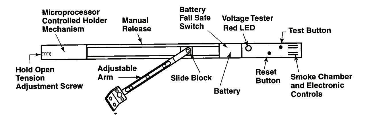
Test Button ..............Push for 2 sec. to release door holder.
Reset Button ...................................
Smoke Chamber ....... Ionization Chamber detects smoke and particles of
combustion...signaling a held open door to release.
LED Voltage Tester...... Monitors the battery voltage once every 40 sec. A low battery
condition will signal the holder to release...thus providing a
FAIL SAFE condition.
Battery Holder...........Uses standard 9 Volt Eveready Energizer #522 battery or
Duracell #MN1604. Do not substitute other brands.
Fail Safe Switch ......Removal of Battery Cover causes a held open door to
release. A good battery must be installed and the cover in
place before holder can be activated.
Slide Block..... Engages holder mechanism to hold door open.
Adjustable Arm......Connects door to slide block. Adjustable for Single Point hold open.
90° - 130° when Pull Side mounted. 90° - 180° when Push Side mounted.
Microprocessor .......Mechanism "Holds" when Reset Switch is pushed.
Holder Mechanism ...... Mechanism "Releases" when:
Test Button is pushed Smoke is detected Battery voltage low Battery impedance high Battery cover removed
Manual Release .........Pulling door toward the closed position will release the holder
mechanism. Pushing the door fully open will reset the holder.
Replace Battery Yearly On A Regular Maintenance Schedule
Note: A held open door will release automatically when smoke is detected. It is necessary to push the reset button after the smoke clears the chamber. This will re-arm the holder mechanism.