First Choice Building Products 3700 Series Rim Latching Exit Device Installation Manual
Open the original PDF document
View PDF

Series 3700 Rim Latching Exit Device
(630) 350-2770 WWW.firstchoicebuildingproducts.com
FOR DOORS WITHOUT KEY CYLINDERS
TO INSTALLING ACTIVATING DEVICE
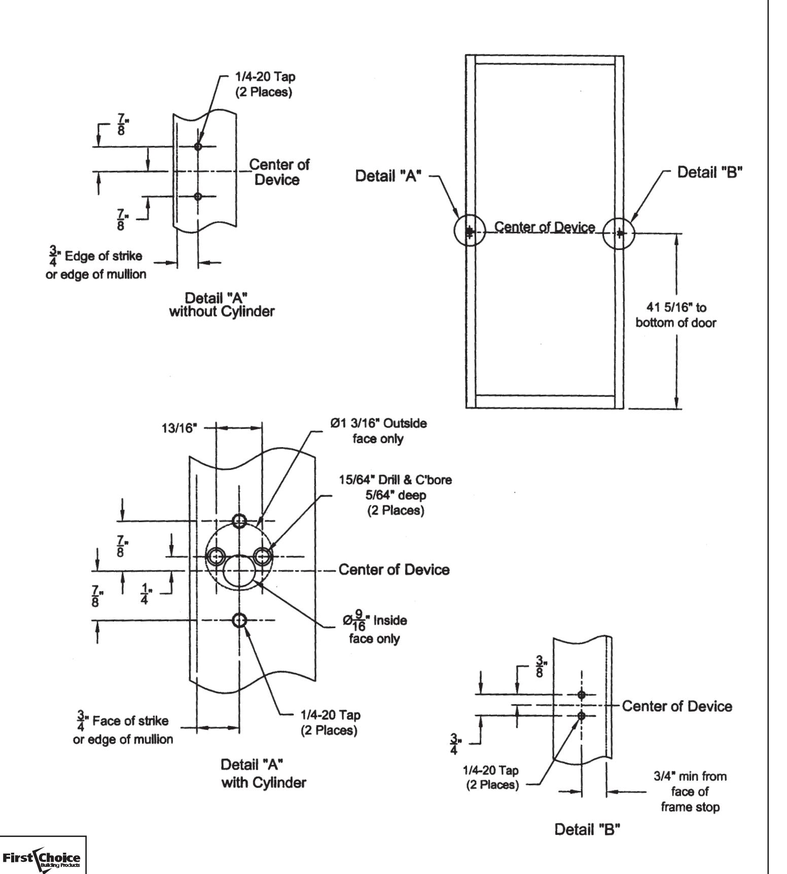
Prepare doors, omitting the cylinder holes, as per template on page 8.
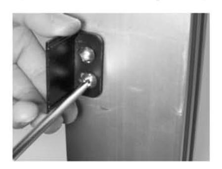
Install the hinge stile mounting bracket with 2 ea. 1/4-20 x 1/2" pan head screws leaving space to capture the base of the device (see next step).
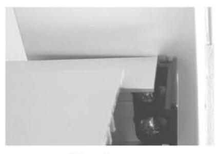
Fig. A
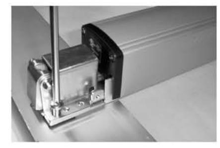
Fig. B
Slip the device base under the mounting bracket (Fig. A) and attach device to the lock stile with 2 ea. 1/4-20 x 3/4" screws (Fig. B). Tighten all four 1/4-20 screws to secure the device.
MOUNT INACTIVE AND ACTIVE COVERS.
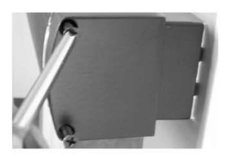
Mount the inactive side end cap using 2 ea. #8-32 x 1 1/2" screws.
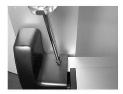
Install the active side cover, with the device un-dogged, using 2 ea. #10-32 x 3/8" screws.
FOR DOORS WITH KEY CYLINDER
Prepare doors as per template on page 8.
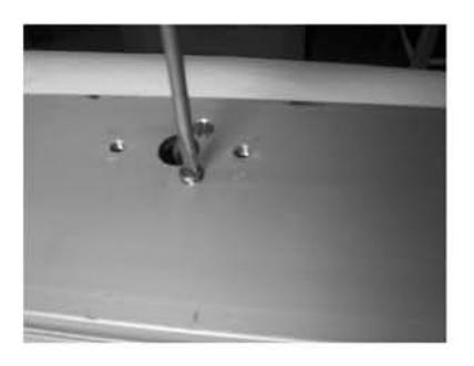
Trim the cylinder tail piece so that it is slightly below the door face after mounting.
Install key cylinder using mounting screws supplied with the cylinder. (The screws may need to be shortened.)
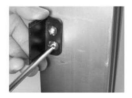
Install the hinge stile mounting bracket with 2 ea. \( \frac{1}{4}-20 \text{ x } \frac{1}{2} \) pan head screws leaving space to capture the base of the device (see next step).
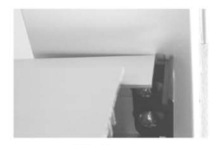
Fig. A
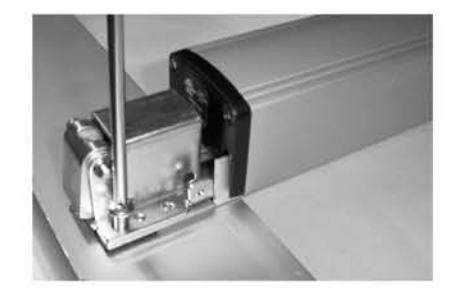
Fig. B
Slip the device base under the mounting bracket (Fig. A) and attach device to the lock stile with 2 ea. \( \frac{1}{4}\)-20 x 3/4" screws (Fig. B). Tighten all four \( \frac{1}{4}\)-20 screws to secure the device.
MOUNT INACTIVE AND ACTIVE COVERS-SEE PAGE 2.
Setting Cylinder Function
All cylinder retractors are factory set for Night Latch function. To set for Hold Back function, simply remove the set screw to allow additional rotation of the cylinder tailpiece.
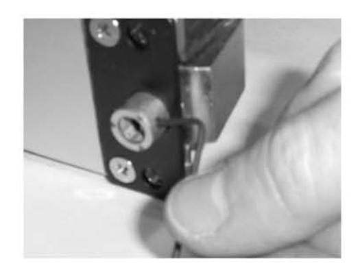
INSTALLING THE FRAME STOP
Prepare the door frame as shown on page 5.
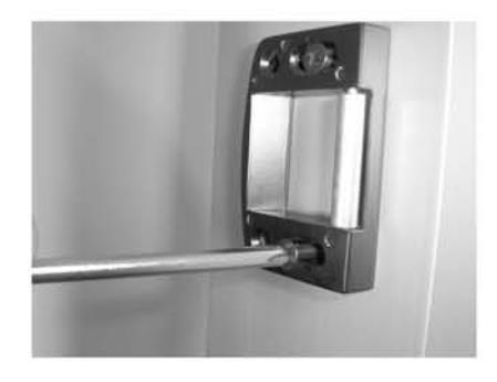
Install the roller strike with two each #10-32 x 1" screws so that the roller edge is flush with the frame stop. (Use strike shim for 5/16" stops.)
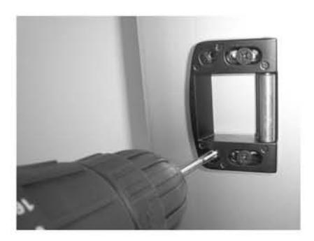
Using the roller strike as a template drill and tap rear mounting holes. Install remaining 10-32 x 1" mounting screws and tighten all four screws.
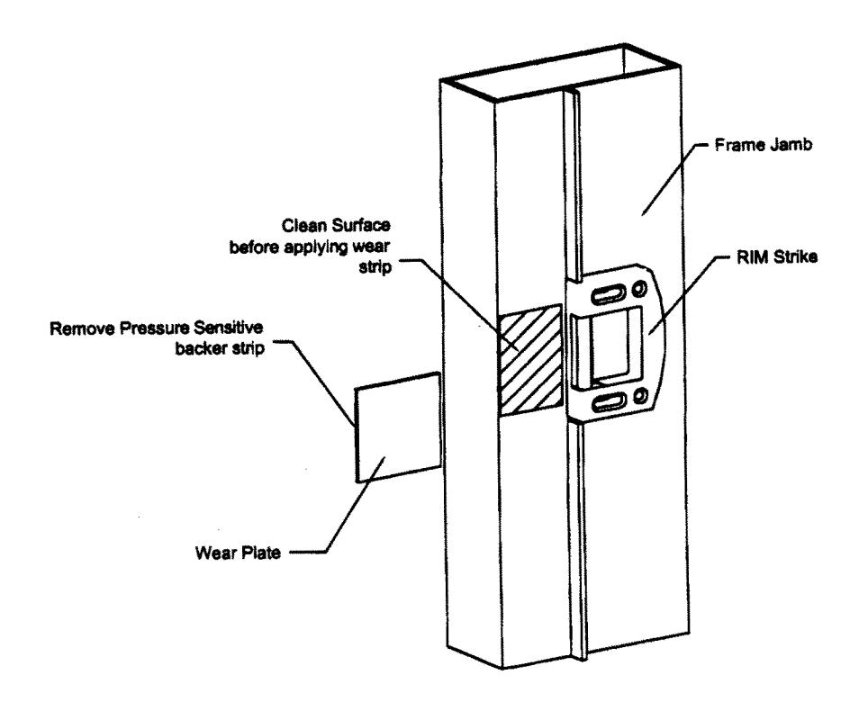
Locate the adhesive backed Wear Strip as shown on page 5 and mount in place.
Installing Wear Strip
- Cut wear strip to desired length. Clean surface of frame jamb before applying wear strip in indicated area.
- 3. Peel backer paper from wear strip.
- 4. Apply wear strip flush to front of frame jamb in indicated area.
FOR MULLION APPLICATION SEE INSTRUCTIONS FOR SERIES RM300 MULLIONS
FCBP Document Control No. 30M37
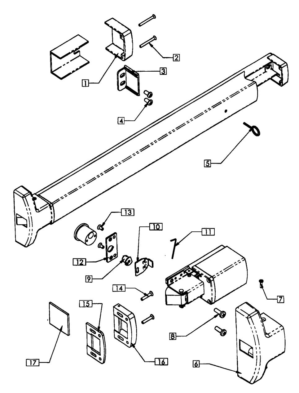
| Reference | Decemberation | 5 4 4 | Quantity |
|---|---|---|---|
| Number | Description | Part Number | Per Device |
| 1 | Hinge Stile Push Bar End Cap | 30 | 1 |
| 2 | End Cap Screw | 802 | 2 |
| 3 | Channel End Cap | 33 | 1 |
| 4 | Hinge Stile Mounting Screws | 801 | 2 |
| 5 | Dogging Key | 819 | 1 |
| 6 | Center Cover | 40A | 1 |
| 7 | Cover Screw | 804 | 2 |
| 8 | LS Mounting Screws | 826 | 2 |
| 9 | Cylinder Cam | 9039 | 1 |
| 10 | Retractor | 35 | 1 |
| 11 | Allen Wrench | 825 | 1 |
| 12 | Cam Spacer Plate | 31 | 1 |
| 13 | Spacer Plate Screws | M817 | 2 |
| 14 | Stike Mounting Screw | 836 | 4 |
| 15 | Strike Shim | 17001423 | 1 |
| 16 | Strike Assy. | 17001A05 | 1 |
| 17 | UHMD Wear Strip | 17001288 | 1 |
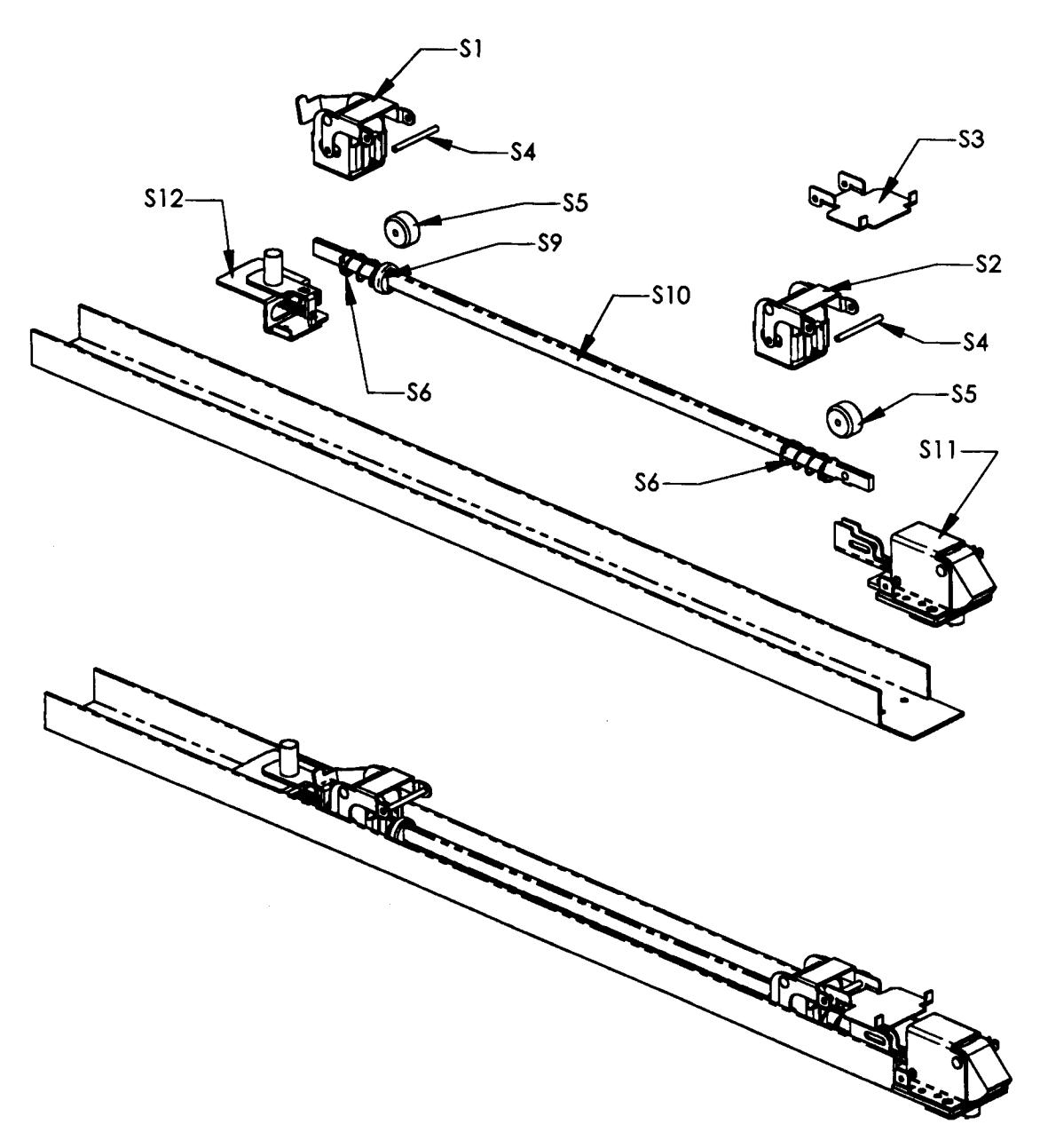
| Reference | Down Normalian | Quantity | |
|---|---|---|---|
| Number | Description | Part Number | Per Device |
| S1 | Hinge Stile Activating Bracket | 71 | 1 |
| S2 | Lock Stile activationg Bracket | 9034 | 1 |
| S3 | Push Bar Bracket | 15 | 11 |
| S4 | Push Bar Axle Pin | 16 | 2 |
| S5 | Roller Stop | 17 | 2 |
| S6 | Spring | 23 | 2 |
| S9 | Spring Cap | 24 | 1 |
| S10 | Activating Connecting Rod | 21 | 1 |
| S11 | Rim Latch Bracket Assy. | 9032 | 1 |
| S12 | Dogging Kit | 71 | 1 |
| ADDITIONAL ITEMS NOT REFERENCED- | ||||
|---|---|---|---|---|
| LS End Cap | 50 | 1 | ||
| LS End Cap Screw | 838 | 2 | ||
| Push Bar Activating Assy - 36" - Clear | 370036-CL | 1 | ||
| Push Bar Activating Assy - 36" - Dark Brz | 370036-BR | 1 | ||
RIM Panic Installation Template All prep is on interior side of door, except where noted.
Right Hand door shown. (LHRB)