Falcon Cross Bar Exit Devices Catalog 109432
Open the original PDF document
View PDF

Table of contents
- XX-R Series
- F-XX-R Series
- XX-V Series
- F-XX-V Series
- XX-M Series
- F-XX-M Series
- XX-C Series
- F-XX-C Series
- 1990 Series
- 2090 Series
- 14-16 Accessories
- Trim designs
- Trim chart
- Door application
- 20-21 Type and function
- How to order
The Falcon difference
Safety, security and uncompromising value
At Falcon, we know that every product you sell not only has to meet local building codes, but also your expectations for performance and quality. We take your expectations seriously, and that's why we build our crossbars to deliver durability, convenience and unmatched value. After all, we've built our reputation on the same standards that you have – providing quality products at a reasonable price delivered on time. It's the way we do business and it's what makes Falcon a powerful choice no matter what your project.
XX-R Series
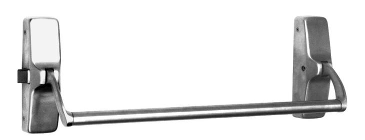
Non-handed rim device
Panic exit hardware
The Falcon XX-R Series rim device is produced to meet the demanding requirements of higher traffic installations. This device is a single point, rim type latch with the traditional crossbar design.
(optional)
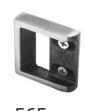
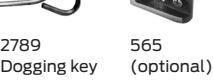
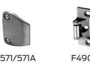
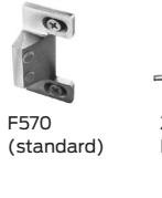
Strike
| Device | Length | Strike |
Min.
stile |
Door
opening width |
|---|---|---|---|---|
| XX-R-EO | 4' |
565 flush
565 F570/F490 |
3 1
⁄4" 3 3⁄4" 4" |
2'6" up to 3'10"
2'6" up to 3'11" 2'6" up to 4'0" |
Note: See page 15 for additional strike information. Approximate. See appropriate templates.
| Hand: | Field reversible. |
|---|---|
| Functions: |
All functions built into "EO" (exit only) device. For K or
L trim, add 3755 K hub. See trim selection chart on page 18 |
| Finishes: |
US3 (605); US4 (606); US10 (612); US26 (625);
US26D (626); US32 (629); US32D (630); SP313 (695) |
| Strikes: |
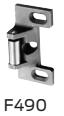
F570 adjustable strike standard
565, 571, 571A, F490 strike optional |
| Arms: |
Forged brass, aluminum and investment cast stainless
steel |
| Crossbars: |
1" O.D., brass, bronze and stainless steel.
Reinforced crossbars available |
| Latchbolt: | Stainless steel, 3⁄4" throw |
| Deadlocking latchbolt: | Optional; Specify "DL" prefix |
| Dogging feature: |
1
⁄2" turn hex dogging standard; No threaded parts to wear out |
| Stock sizes: | 4'0" standard |
| Doors: |
1 3⁄4" thick, wood or metal; Specify thickness if other
than 1 3⁄4" |
| Projection: | 5" maximum; 4" dogged |
| Mounting height: |
40 1
⁄4" from CL to finished floor |
| Fasteners: |
All mounting screws are concealed. Sheet metal
screws standard; Machine screws available, specify AMS |
| Sex bolts: |
When device is used with hollow core wood, composite
or light gauge hollow metal doors, specify 8-#2729 SNB when through-bolted trim is used, specify 4-#2729 SNB |
| ANSI: | Certified ANSI A156.3 grade 1 standards |
|
Center case and
working parts: |
Center case is pressure die cast aluminum with heavy
wrought, forged, investment cast and sintered metal parts |
F-XX-R Series
Non-handed rim device
Z Fire exit hardware
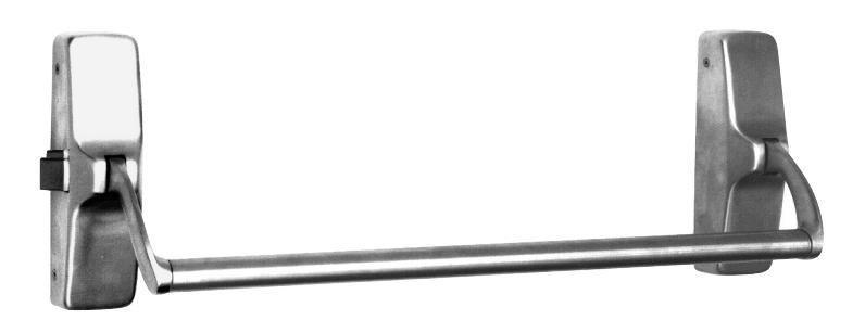
The Falcon F-XX-R SeriesZfire rated rim device is produced with the demanding standards required for a quality fire rated device. The investment cast stainless steel chassis, stainless steel latchbolt and standard deadlocking feature provide years of reliable service in higher traffic installations. The F-XX-R device is a single point, rim type latch with the traditional crossbar design.
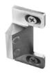
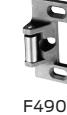
F570 (standard)
F490 Strike
| Device | Length | Strike | Stile |
Opening
width |
|---|---|---|---|---|
| F-XX-R-EO | 4' |
F570/
F490 |
4" |
2'6" up
to 4'0" |
Note: Approximate. See appropriate templates.
| Hand: | Field reversible. |
|---|---|
| UL: |
"A" label (3 hr.); 4'0" x 8'0"; 8'0" x 8'0". "B" label (1 1
⁄2 hr.) 8'0" x 8'0" with KRF-4023 mullion |
| Functions: |
All built into "EO" (exit only) device; For K or L trim, add
3755 K hub; See trim selection chart on page 18 |
| Finishes: |
US3 (605); US4 (606); US10 (612); US26 (625); US26D
(626); US32 (629); US32D (630); SP313 (695) |
| Strikes: | Stainless steel, F570 or F490 |
| Arms: |
Forged brass, aluminum and investment cast stainless
steel |
| Crossbars: |
1" O.D., brass, bronze and stainless steel; Reinforced and
crossbars available |
| Latchbolt: | Stainless steel, 3⁄4" throw |
| Deadlocking latchbolt: | Standard |
| Stock sizes: | 4'0" standard. |
| Doors: |
1 3⁄4" thick, wood or metal; Specify thickness if other than
1 3⁄4" |
| Projection: | 5" maximum |
| Mounting height: |
40 1
⁄4" from CL to finished floor |
| Fasteners: |
All mounting screws are concealed; Furnished with all
machine screws |
| Sex bolts: |
When used with wood, composite or non-reinforced
hollow metal, sex bolts must be specified, 10-#2729 SNB required; If through-bolted trim is used, 6-#2729 SNB required |
| ANSI: | Certified ANSI A156.3 grade 1 standards |
|
Center case and
working parts: |
Center case is investment cast stainless steel with heavy
wrought, forged, investment cast and sintered metal parts |
XX-V Series
Reversible vertical rod device
Panic exit hardware
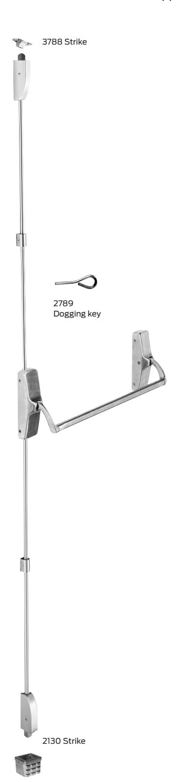
The Falcon XX-V Series vertical rod device is designed to meet the demanding requirements of higher traffic installations. The XX-V device is a surface-applied vertical rod type with the traditional crossbar design.
| Hand: | Field reversible | |
| Functions: | See trim selection chart page on 18 | |
| Finishes: |
US3 (605); US4 (606); US10 (612); US26 (625); US26D (626); US32
(629); US32D (630); SP313 (695) |
|
| Strikes: | 3788 strikes are surface applied. 2130 strike is mortised into floor. | |
| Angle bracket: |
Use 4215 angle bracket in flush transom installations; Allows use of
standard 3788 strike |
|
| Arms: | Forged brass, aluminum and investment cast stainless steel | |
| Crossbars: |
1" O.D., brass, bronze and stainless steel; Reinforced
crossbars available |
|
| Latchbolt: |
Top stainless steel, 3⁄4" throw; Bottom stainless steel bolt, 1
⁄2" throw |
|
| Deadlocking latchbolt: | Standard | |
| Latch retention hold: | Standard with top latch | |
| Dogging feature: |
⁄2" turn hex dogging standard; No threaded parts to wear out
1 |
|
| Stock sizes: | 4'0" standard | |
| Doors: | 1 3⁄4" thick, wood or metal; Specify thickness if other than 1 3⁄4" | |
| Projection: | 5" maximum, 4" dogged | |
| Stile: |
3 1
⁄2" minimum when used in pairs |
|
| Fasteners: |
All mounting screws are concealed; Sheet metal screws standard;
Machine screws available, specify AMS |
|
| Sex bolts: |
When device is used with hollow core wood, composite or light gauge
hollow metal doors, specify 8-#2729 SNB when through-bolted trim is used, specify 4-#2729 SNB |
|
| ANSI: | Certified ANSI A156.3 grade 1 standards | |
| XX-V: |
Latch retention latch top; 3788 strike top, bottom bolt 2130 flush strike
bottom |
|
| XX-V-LBR: | Less bottom rod vertical device | |
| Vertical rods: |
Furnish to length based on a 40 1
⁄4" horizontal CL from finished floor, and a 7'0" door standard; Variations from these standards must be specified when ordering |
|
F-XX-V Series
Reversible vertical rod device
<sup>Z</sup> Fire exit hardware
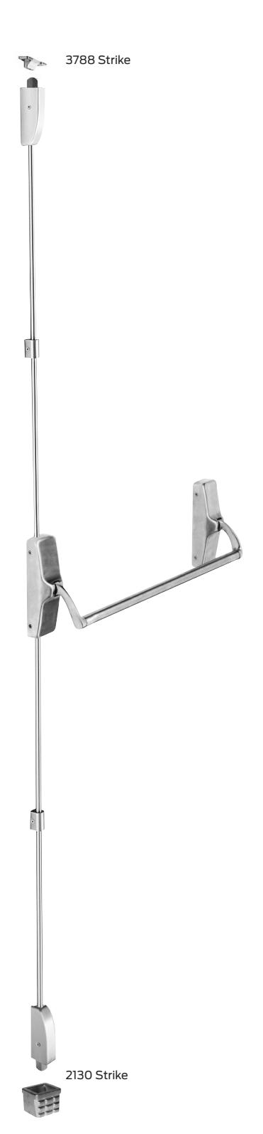
The Falcon F-XX-V Series Z fire rated vertical rod device is designed to meet the demanding requirements of higher traffic installations. The F-XX-V is a fire rated surface-applied vertical rod type with the traditional crossbar design.
| Hand: | Field reversible. | |
|---|---|---|
| UL: |
"A" label (3 hr.); 8'0" x 10'0" double egress; 8'0" x 10'0"
(F-XX-M x F-XX-V) "B" label (3 hr.); 8'0" x 10'0" double egress; 8'0" x 10'0" |
|
| Functions: | See trim selection chart on page 18 | |
| Finishes: | US3 (605); US4 (606); US10 (612); US26 (625); US26D (626); US32 (629); US32D (630); SP313 (695) | |
| Strikes: |
3788 strikes are surface applied, standard;
2130 strike is mortised into floor |
|
| Arms: | Forged brass, aluminum and investment cast stainless steel | |
| Crossbars: | 1" O.D., brass, bronze and stainless steel; Reinforced crossbars available | |
| Latchbolt: | Top stainless steel, " throw; Bottom stainless steel bolt, " throw | |
| Deadlocking latchbolt: | Standard | |
| Latch retention hold: | Standard with top latch | |
| Stock sizes: | 4'0" standard | |
| Doors: | 1³/₄" thick, wood or metal; Specify thickness if other than 1³/₄" | |
| Projection: | 5" maximum | |
| Stile: | 3 ½" minimum when used in pairs | |
| Fasteners: | All mounting screws are concealed; All machine screws standard | |
| Sex bolts: | When device is used with hollow core wood, composite or light gauge hollow metal doors, specify 8-#2729 SNB when through-bolted trim is used, specify 4-#2729 SNB | |
| ANSI: | Certified ANSI A156.3 grade 1 standards | |
| F-XX-V: | Latch retention latch top; 3788 strike top, bottom bolt 2130 flush strike bottom | |
| F-XX-V-LBR: | Less bottom rod vertical device with side-of-door-mounted auxiliary fire latch (AFL), "A" label (3 hr.), 8'0" x 8'0" double egress (20 min. fire rating on wood doors.) | |
| Vertical rods: | Furnished to length based on a 40 " horizontal CL from finished floor, and a 7'0" door standard; Variations from these standards must be specified when ordering | |
XX-M Series
Mortise device
Panic exit hardware
The Falcon XX-M Series mortise device offers great value with attractive styling and the security of a mortise lock. This device is a single-point, mortise latch type featuring the traditional crossbar design. The heart of the XX-M device is the Falcon mortise lock, which is known for its reliability and trouble-free operation.
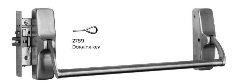
| Hand: | Handed, specify when ordering | |
| Functions: |
Mortise lock determines function. When ordering device only, specify
device with function less trim; See trim selection chart on page 18 |
|
| Finishes: |
US3 (605); US4 (606); US10 (612); US26 (625); US26D (626); US32
(629); US32D (630); SP313 (695) |
|
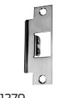
| Strikes: | 1279 standard; F1280/1280A | |
| Arms: | Forged brass, aluminum and investment cast stainless steel | |
| Crossbars: | 1" O.D., brass, bronze, and stainless steel; Reinforced crossbars available | |
| Latchbolt: | 3⁄4" throw; Molydag coated steel | |
| Deadlocking latchbolt: | Standard | |
| Dogging feature: |
1
⁄2" turn hex dogging standard; No threaded parts to wear out |
|
| Stock sizes: | 4'0" standard | |
| Doors: | 1 3⁄4" thick, wood or metal; Specify thickness if other than 1 3⁄4" | |
| Projection: | 5" maximum, 4" dogged | |
| Stile: |
4 1
⁄2" minimum |
|
| Mounting height: |
40 1
⁄4" from CL to finished floor; For mortise lock prep per ANSI A115.1-1990 |
|
| Fasteners: |
All mounting screws are concealed; Sheet metal screws standard for
device, mortise lock is machine screws; All machine screws available, specify AMS |
|
| Sex bolts: |
When device is used with hollow core wood, composite or light gauge
hollow metal, specify 8-#2729 SNB; When through-bolted trim is used, specify 4-#2729 SNB |
|
| ANSI: | Certified ANSI A156.3 grade 1 standards | |
|
Mortise lock:
Heavy wrought lock case with investment cast or sintered stainless steel parts; Lock face is forged brass—fits standard cutout; Locks are designed to fit standard preparation ANSI A115.1 for 1 3⁄4" doors; Deadlocked when auxiliary bolt is depressed 5⁄16" |
||
F-XX-M Series
Mortise device
Z Fire exit hardware
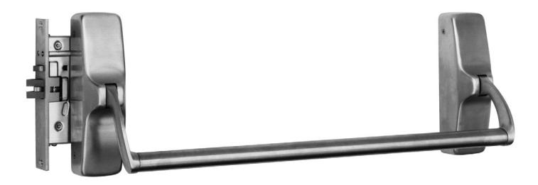
The Falcon F-XX-M SeriesZfire rated mortise device offers great value, good looks and security of a mortise lock. This fire rated device is a single-point, mortise-latch type, featuring the traditional crossbar design. The heart of the F-XX-M device is the Falcon mortise lock, which is known for its reliability and trouble-free operation.
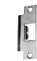
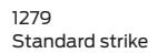
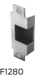
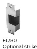
Optional strike
| Hand: | Handed, specify when ordering. | |||
| UL: | "A" label (3 hr.); 4'0" x 8'0"; 8'0" x 10'0" | |||
| (F-XX-M x F-XX-V or F-XX-C) | ||||
|
"B" label (1 1
⁄2 hr.) with F1280 open back strike |
||||
| Functions: | Mortise lock determines function; When ordering, specify device with | |||
| function less trim; See trim selection chart on page 18; | ||||
| Finishes: | US3 (605); US4 (606); US10 (612); US26 (625); US26D (626); US32 | |||
| (629); US32D (630); SP313 (695) | ||||
| Strikes: |
1279 standard; F1280 optional, "B" label (1 1
⁄2 hour) |
|||
| Arms: | Forged brass, aluminum and investment cast stainless steel | |||
| Crossbars: | 1" O.D., brass, bronze and stainless steel; Reinforced crossbars available | |||
| Latchbolt: | 3⁄4" throw; Molydag coated steel | |||
| Deadlocking latchbolt: | Standard | |||
| Stock sizes: | 4'0" standard. | |||
| Doors: | 1 3⁄4" thick, wood or metal; Specify thickness if other than 1 3⁄4" | |||
| Projection: | 5" maximum | |||
| Stile: |
4 1
⁄2" minimum |
|||
| Mounting height: |
40 1
⁄4" from CL to finished floor; For mortise lock prep per ANSI A115.1-1990 |
|||
| Fasteners: | All mounting screws are concealed; All machine screws standard | |||
| Sex bolts: | When device is used with wood, composite or non-reinforced hollow metal | |||
| doors, specify 8-#2729 SNB. When through-bolted trim is used, specify | ||||
| 4-#2729 SNB | ||||
| ANSI: | Certified ANSI A156.3 Grade 1 standards | |||
| Mortise lock: | Heavy wrought lock case with investment cast or sintered stainless steel | |||
| parts; Lock face is forged brass—fits standard cutout; Locks are designed to | ||||
| fit standard preparation ANSI A115.1 for 1 3⁄4" doors; Deadlocked when | ||||
| auxiliary bolt is depressed 5⁄16" | ||||
XX-C Series
Reversible concealed vertical rod device
Panic exit hardware
The Falcon XX-C Series concealed vertical rod device offers great value and design with the security of two-point latching and panic exit functionality. The XX-C device is a concealed vertical rod type with the traditional crossbar design.
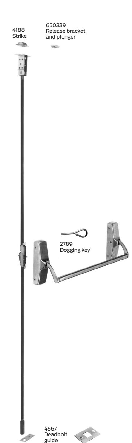
Specifications
| Hand: | Field reversible | |
|---|---|---|
| Functions: | See trim selection chart on page 18; Delta trim only | |
| Finishes: |
US3 (605); US4 (606); US10 (612); US26 (625); US26D (626); US32
(629); US32D (630); SP313 (695) |
|
| Strikes: | 4188 mortised top; 2130 and 4155 flush strike bottom | |
| Arms: | Forged brass, aluminum and investment cast stainless steel | |
| Crossbars: |
1" O.D., brass, bronze and stainless steel; Reinforced
crossbars available |
|
| Latchbolt: |
Top stainless steel, 3⁄4" throw; Bottom stainless steel bolt, 1
⁄2" throw |
|
| Deadlocking latchbolt: | Standard | |
| Latch retention hold: | Standard in top latch | |
| Dogging feature: |
1
⁄2" turn hex dogging standard; No threaded parts to wear out |
|
| Stock sizes: | 4'0" standard. | |
| Doors: | 1 3⁄4" thick, metal or wood; Specify thickness if other than 1 3⁄4" | |
| Projection: | 5" maximum, 4" dogged | |
| Stile: | 3" minimum when used in pairs (6" minimum on wood doors) | |
| Fasteners: |
All mounting screws are concealed; Sheet metal screws standard;
Machine screws available, specify AMS |
|
| Sex bolts: |
When non-reinforced hollow metal doors are used specify 8-#2729
SNB; with through-bolted trim, use 4-#2729 SNB |
|
| ANSI: | Certified ANSI A156.3 grade 1 standards | |
| XX-C-LBR: |
Less bottom rod concealed vertical device with side-of-door mounted
auxiliary fire latch (AFL). 20 min., 4'0" x 8'0", 8'0" x 8'0" (with steel channel door construction) |
|
| Vertical rods: |
Furnished to length based on a 40 1
⁄4" horizontal CL from finished floor, and a 7'0" door standard; Variations from these standards must be specified when ordering |
|
| Patented centerslide: | For ease of adjustment | |
2130 Strike
4155 Strike
F-XX-C Series
Reversible concealed vertical rod device
Z Fire exit hardware
The Falcon F-XX-C SeriesZfire rated concealed vertical rod device offers dependable value, classic styling and aesthetics with the security of two-point latching. The F-XX-C device is a concealed vertical rod type with the traditional crossbar design.
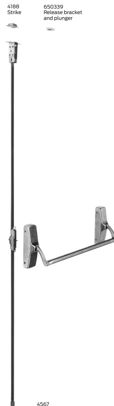
Specifications
| Hand: | Field reversible. | |
| UL: |
"A" label (3 hr.); 4'0" x 10'0"; double egress 8'0" x 10'0";
(F-XX-M x F-XX-C) |
|
| Functions: | See trim selection chart on page 18; Delta trim only | |
| Finishes: |
US3 (605); US4 (606); US10 (612); US26 (625); US26D (626);
US32 (629); US32D (630); SP313 (695) |
|
| Strikes: | 4188 mortised top; 2130 flush strike bottom | |
| Arms: | Forged brass, aluminum and investment cast stainless steel | |
| Crossbars: |
1" O.D., brass, bronze and stainless steel; Reinforced crossbars
available |
|
| Latchbolt: |
Top stainless steel, 3
⁄4" throw; Bottom stainless steel bolt, 1 ⁄2" throw |
|
| Deadlocking latchbolt: | Standard | |
| Latch retention hold: | Standard in top latch | |
| Stock sizes: | 4'0" standard | |
| Doors: |
1 3
⁄4" thick metal or wood only; Specify thickness if other than 1 3 ⁄4"; 6" minimum on wood doors |
|
| Projection: | 5" maximum | |
| Stile: | 3" minimum when used in pairs; 6" minimum on wood doors | |
| Fasteners: | All mounting screws are concealed; All machine screws standard | |
| Sex bolts: |
When non-reinforced Hollow Metal doors are used, specify 8-#2729
SNB; with through-bolted trim, use 4-#2729 SNB |
|
| ANSI: | Certified ANSI A156.3 grade 1 standards | |
| F-XX-C-LBR: |
Less bottom rod concealed vertical device with side-of-door
mounted auxiliary fire latch (AFL) "A" label (3 hr.), 8'0" x 8'0" double egress |
|
| Vertical Rods: |
Furnished to length based on a 40 1
⁄4" horizontal CL from finished floor, and a 7'0" door standard; Variations from these standards must be specified when ordering |
|
| Patented centerslide: | For ease of adjustment | |
4567 Deadbolt Guide
2130 Strike
1990 Series
Concealed vertical rod crossbar device
Tough crossbar design.
The classic look of 1990 has a long history of reliable performance. It is equipped with hardened steel latches and adjustable strike to ensure safety, security and quiet operation.
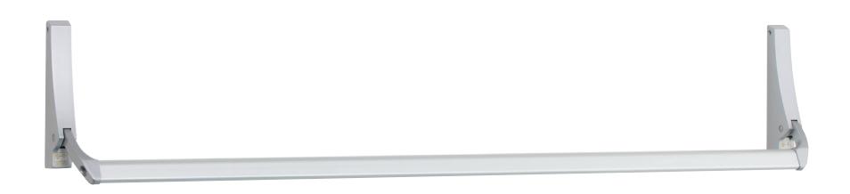
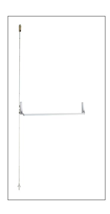
Specifications
| Hand: | Field reversible, non handed. |
| Functions: | See trim selection chart on this page. |
| Finishes: | P28, P13, P35, US26D. |
| Strikes: | PB48 top. |
| Latches: |
Hex bottom latch (standard), RL - rod bottom latch,
PL - Pullman bottom latch, ES - electric strike top latch (optional). Device needs to be less bottom rod (LBR). |
| Dogging feature: | Hex dogging standard. |
| Cylinder: |
Rim, key entry (NL) or hold back (HB) available
(field selectable) |
| Sizes: |
Field adjustable width, 41" crossbar standard extra length
cross bar available. |
| Doors: |
1 3
⁄4" thick metal doors. |
| Projections: |
4 3
⁄8" extended, 2 1 ⁄2" depressed. |
| Stile: |
1 3
⁄4" minimum. |
| Fasteners: | All mounting screws are concealed. |
| ANSI: | Certified ANSI A156.3 grade 1 standards. |
| UL: | UL305 listed. |
| Vertical rods: | 7' standard, extension rod kits available up to 10'. |
Positioning retractor as shown for NL or HB functions.
Install retractor as shown below for both RHR and LHR doors; this makes all keys function in the same direction.
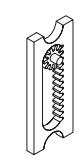
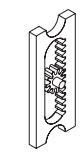
Hold back (HB) Night latch (NL)
| Model | Trim Package | Type | Function |
|---|---|---|---|
| 1990 | No outside trim | 6 | 01 |
| 1991 | Pull only (9970) | 6 | 02 |
| 1992 | Cylinder only | 6 | 03/04 |
| 1993 | Pull and cylinder | 6 | 02/03/04 |
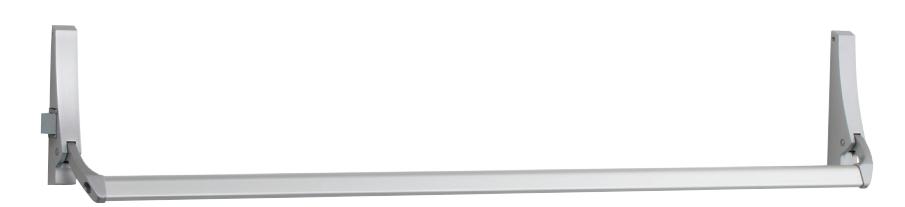
2090 Series
Rim crossbar device
Classic looks in a rim exit device.
The 2090 provides balanced appearance, dependable performance and economical pricing, making it a popular choice where rim exit devices are required.
If cylinder is used, set pinion cam on back of active housing for hold-back (HB) or night latch (NL) operation.
Hold-back (HB)
Turning key one complete rotation retracts latchbolt. If key is removed in this position, latchbolt stays retracted. Returning key to original position before removing allows latchbolt to extend.
cam
Latch
To set for hold-back: Turn pinion cam until latchbolt starts to retract, then turn pinion cam the other way as far as it will go. Leave pinion cam in this position.
Night latch (NL)
Turning key as far as it will go retracts latchbolt. Key must be returned to original position to be removed, leaving the door locked.
To set for night latch: Turn pinion cam until latchbolt starts to retract. Leave pinion cam in this position.
| Hand: | Specify RHR or LHR, not reversible |
| Functions: | See trim selection chart on this page |
| Finishes: | P28, P13, P35, US26D |
| Strikes: | SD36 standard, see page 17 for other rim strikes available |
| Latchbolt: | 1/2" throw hardened steel |
| Dogging feature: | Hex dogging standard |
| Cylinder: | Rim, key entry (NL) or hold back (HB) available (field selectable) |
| Sizes: | Field adjustable width, 41" crossbar standard extra length crossbars available |
| Doors: | thick metal or wood doors, specify if wood door; 9970 is for use on HM and Alum doors only; Not for use on wood doors |
| Projections: | 4 3 / 8 " extended, 2 1 / 2 " depressed |
| Stile: | 1 ³/₄" minimum |
| Fasteners: | All mounting screws are concealed |
| UL: | UL305 listed |
| Mullions: | Removable mullions are available for pairs of doors, see page 14 |
| Model | Trim package | Type | Function |
|---|---|---|---|
| 2090 | No outside trim | 4 | 01 |
| 2091 | Pull only (9970) | 4 | 02 |
| 2092 | Cylinder only | 4 | 03/04 |
| 2093 | Pull and cylinder | 4 | 02/03/04 |
Accessories
Mullions
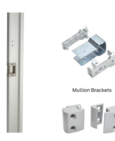
RM 70 Removable mullion
RM 70 for use with 2090 Series comes complete with adjustable mortised strikes and security clips. Compatible with doors 7' to 10' and for use with stiles as narrow as 1 3⁄4". Made of aluminum, they are available in anodized aluminum or bronze finishes. Mullion is 3 1 ⁄2" deep, 1" wide on door side, and 1 5⁄8" at the widest point.
Mullion strikes
RM 70
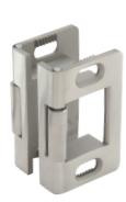
Adjustable mortise strikes (pair). 2 3⁄8" tall 1 7 ⁄16" wide 1" thick STK70
525 Mullion Stabilizer

Removable mullion
- § The 2923, (F)4023 and KR(F)-4023 steel mullions are for use with the XX-R devices on double door openings. Advantage: Increased security and tighter closure. Minimizes door warpage and sag. Regulates the flow of in-and-out traffic.
- § Falcon removable mullions are easilyt removed and reinstalled for full width access.
- § Rim devices are used on both leaves, attaining a perfectly symmetrical opening.
- § The mullion assembly consists of a mullion, top and bottom mounting brackets and a screw pack. Soffit adapters are available for use with either the 2923 or the 4023 mullion. Please see Price Book for ordering information.
- § The (F)4023 and KR(F)-4023 fire-rated mullion also includes four stabilizer blocks as required for labeled installations.
- § Strikes are not furnished with the mullion. Please see page 15 for strike information.
- § Mullions may be cut on the job for doors under stock lengths.
- § KR Mullions require 1 1 ⁄4" mortise cylinders with standard "A" cam.
Mullion features
- § Mullion fittings ductile iron.
- § (F)4023, cylinder removable mullions KR(F)-4023 2" x 3" x height.
- § 2923 mullion 1 1 ⁄2" x 2 1 ⁄2" x height.
- § Prime coat only.
- § 7' or 8' door opening standard, other door openings as specified.
Strikes
For (F) XX-R rim devices (center latching)
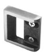
565
Adjustable surface mounted for use with blade or applied stops.

P
F490
F570/F490
Adjustable strike.

571/571A
Used on inactive leaf for device on active leaf of pair of doors without removable mullion. 571 keeps 2 <sup>7</sup>/16" backset. 571A is trimmer and projects less into opening.
For all mortise lock devices (F) XX-M

1279
To ASA dimensions. Closed strike used on single doors and on fire exit hardware doors with coordinator.
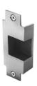
F1280
Open back strike used
on pairs of " doors without astragal or coordinator. To basic ASA dimensions and can be used on stock hollow metal doors. Use 1280A for 2 " doors. F-1280 B label ( hr.) stainless steel strike available.

4188
Top strike for (F)XX-C
For (F) XX surface vertical rod and concealed vertical rod devices
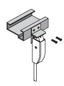
4215
Angle bracket for flush transom applications. Does not require elimination of latch retention feature.
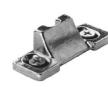
3788
Standard top of (F) XX-V.
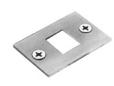
4155
4155 bottom strike for use with (F)XX-V and (F)XX-C

2130
(F)XX-V standard bottom strike for grouting into concrete or masonry floors. Also used with (F)XX-C
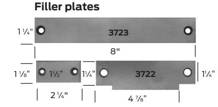
3721/3722/3723
Steel filler plates 3721 Cylindrical lock front filler 3722 ASA Strike filler – set no. SC for 161 cutout
3723 Mortise lock front filler
3722 ASA Strike filler
- set no. SM for 86 cutout
Surface vertical extension rods
Extension rods are available in 12", 24" and 36" lengths in all finishes. Both ends tapped and all-thread included as connector.
Concealed extension rods
Extension rods are available in 12", 24" and 36". Both ends have pressed-in, threaded inserts.
Accessories
Strikes
Concealed vertical rod
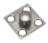
PB48
Top strike for 1990 devices. Packed with three 0.050" thick shims. 1 1 ⁄16" square ⁄16" projection
Rim
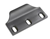
STK45
Strike for inactive leaf, pair of doors with 2090 devices. 3 1 ⁄4" tall 1 5⁄16" wide ⁄4" thick
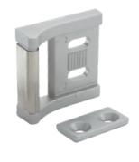
SD35
Strike for 1 ⁄8" x 1 ⁄2" blade stop, 2090 device. 1 3⁄4" tall 1 3⁄4" wide ⁄2" thick
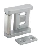
SD36
Strike for all stops, 2090 device. 1 3⁄4" tall 1 3⁄4" wide ⁄2" thick
Pull
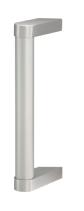
9970
Can be used with all devices. 9 1 ⁄4" center to center 2 7 ⁄8" projection 1 3⁄4" clearance
Cylinders
- § Cylinders for XX-R and XX-V Series devices with cylinder operation are rim cylinders with either horizontal or vertical tailpiece.
- § Cylinders for XX-C and, XX-M and Series devices are mortise cylinders with standard thread (1 5⁄32" -32). The standard cams furnished with most manufacturers mortise cylinders will operate mortise locks, as well as concealed Delta trim operators for XX-C devices. (Cams measure approximately 1" overall and 5⁄16" wide at tip.) Exception: Concealed C & NL require cam B250-295.
- § Cylinder supplied only when specified.
- § 1 1 ⁄4" long with standard cam and "G" keyway only. On Delta C trim for vertical and concealed vertical C and NL functions 1 1 ⁄8" - 1 1 ⁄4" long cylinder by blocking ring required with cam B250-295.
- § Cylinders available keyed and keyed different.
- § XX-M devices using 811K, 812L or 816L trim require a 1 1 ⁄2" cylinder.
Sex Bolts
Sex bolts are available in lengths (under the head) of 12 1 ⁄32". Screws to fit are available in 3⁄4" and 2" lengths to cover a wide range of door thicknesses. B-2729 (#10-24 Thread)
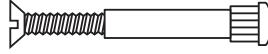
B-4122 (1/4-20 Thread)
Trim designs
Vanguard (820)
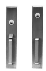
820 TP 820 NL
Escutcheon: 2 <sup>3</sup>/<sub>4</sub>" x 16<sup>1</sup>/<sub>8</sub>" Grip: 6 <sup>1</sup>/<sub>4</sub>" C–C Projection: 2 <sup>1</sup>/<sub>16</sub>" Brass, bronze, stainless steel and aluminum
Apollo (810)
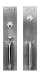
810TP 810NL
Pull: 5 1/2" OC Escutcheon: 3 1/4" x 15" Projection: 2 1/4" Brass, bronze, stainless steel and aluminum
Athena (815)
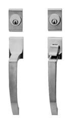
815NL 815TP
Grip Overall: 9 ¹/¹6" Width: 1 ⁵/8" Pull: 6 ¹/4" C–C Projection: 2 ¹/4" Brass, bronze, plated and aluminum
811K
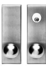
811K-DT 811K 811K-BE
Round Ball Knob Escutcheon: 2 3/4" x 9 3/4" Projection: 3 3/8" Brass, bronze and stainless steel
812L
Dane
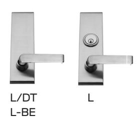
Dane
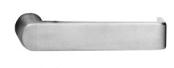
700 Series projection: 2 <sup>7</sup>/<sub>8</sub>" 800 Series projection: 2 <sup>13</sup>/<sub>16</sub>"
Sutro
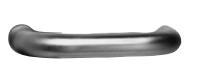
700 Series projection: 3 1/8" 800 Series projection: 3 13/16"
718NL
Quantum
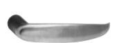
700 Series projection: 3 1/8" 800 Series projection: 3 1/2"
Avalon
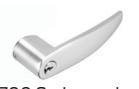
700 Series projection: " 800 Series projection: "
816L
Vandal resistant
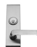
- Heavy duty, vandal resistantTrim operates device even in
- the "broken" position
- Breaks away in either direction (up or down), no internal shear
- Retrofits all existing Falcon lever or knob trims without additional door prep
- · Works with all electric lock
- and unlock functions · Works with rim, surface
- vertical devices and mortise
·Handed
Lever: " Escutcheon: " x " (specify handing) brass, bronze and stainless finishes.
Dane, Quantum and Sutro lever trim return to within of door.
718 Delta (for XX concealed only)
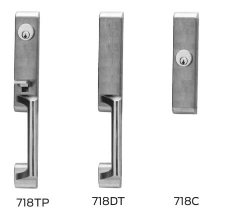
For active trim when locking is not required specify (BE) blank escutcheon. Escutcheon: " 8" Overall length: " Specify handing
717
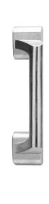
717DT
Escutcheon: 8 1/8" x 1 7/8"
712
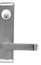
*Dane shown
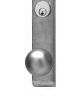
711
712L Control Escutcheon: 8 1/8" x 1 7/8"
711K
Escutcheon: 8 ½8" x 1 ½8" Projection: 3 ½/16"
Trim chart
| Athena (815) | Vanguard (820) | |||||||
|---|---|---|---|---|---|---|---|---|
| Device | DT | NL | TP | DT | NL | TP | TP(BE) | Blank(EO) |
| XX-R | 815 | 815 | 815 | 820 | 820 | 820 | 820 | 820 |
| XX-V | 815 | 815 | 815 | 820 | 820 | 820 | 820 | 820 |
| XX-M | 815 | 815 | 815 | 820 | 820 | 820 | 820 | 820 |
| Apollo (810) | 811K | |||||||
|---|---|---|---|---|---|---|---|---|
| Device | DT | NL | TP | TP(BE) | Blank(EO) | K | K/DT | K(BE) |
| XX-R | 810 | 810 | 810 | 810 | 810 | 811 | 811 | 811 |
| XX-V | 810 | 810 | 810 | 810 | 810 | 811 | 811 | 811 |
| XX-M | 810 | 810 | 810 | 810 | 810 | 811 | 811 | 811 |
| Device | L | L/DT |
Sutro
L(BE) |
|---|---|---|---|
| XX-R | 812 | 812 | 812 |
| XX-V | 812 | 812 | 812 |
| XX-M | 812 | 812 | 812 |
| Device | L | L/DT |
Dane
L(BE) |
|
|---|---|---|---|---|
| XX-R | 812 | 812 | 812 | |
| XX-V | 812 | 812 | 812 | |
| XX-M | 812 | 812 | 812 | |
| Device | L | L/DT |
Quantum
L(BE) |
|---|---|---|---|
| XX-R | 812 | 812 | 812 |
| XX-V | 812 | 812 | 812 |
| XX-M | 812 | 812 | 812 |
| Device | L | L/DT |
Avalon
L(BE) |
|---|---|---|---|
| XX-R | 812 | 812 | 812 |
| XX-V | 812 | 812 | 812 |
| XX-M | 812 | 812 | 812 |
| Device |
Sutro
L |
L/DT | L(BE) |
|---|---|---|---|
| XX-R | 816 | 816 | 816 |
| XX-V | 816 | 816 | 816 |
| XX-M | 816 | 816 | 816 |
| Device | L | L/DT |
Dane
L(BE) |
|---|---|---|---|
| XX-R | 816 | 816 | 816 |
| XX-V | 816 | 816 | 816 |
| XX-M | 816 | 816 | 816 |
| Device | L | L/DT |
Quantum
L(BE) |
|---|---|---|---|
| XX-R | 816 | 816 | 816 |
| XX-V | 816 | 816 | 816 |
| XX-M | 816 | 816 | 816 |
| Device | L | L/DT |
Avalon
L(BE) |
|---|---|---|---|
| XX-R | 816 | 816 | 816 |
| XX-V | 816 | 816 | 816 |
| XX-M | 816 | 816 | 816 |
| Delta | Dane | Avalon | Sutro | Quantum | ||||||||
|---|---|---|---|---|---|---|---|---|---|---|---|---|
| Device | L | BE | DT | L | BE | DT | L | BE | DT | L | BE | DT |
| XX-C | 712 | 712 | 712 | 712 | 712 | 712 | 712 | 712 | 712 | 712 | 712 | 712 |
| Device | TLP | TP | TP-BE | DT | NL | DT | K | K-BE | C |
|---|---|---|---|---|---|---|---|---|---|
| XX-C | 719 | 718 | 718 | 718 | 718 | 717 | 711 | 711 | 718 |
Door application
Label doors
Falcon models F-XX-R, F-XX-V, F-XX-M, and F-XX-C are labeled for use as Zfire exit hardware. UL and Warnock Hersey listed.
Door thickness
| Device | Label | Opening | Application |
|---|---|---|---|
| Hollow meta | ıl door | ||
| F-XX-R | X-R 3 hr. 4' x 8' |
Single, pair, same egress w/
F-4023 mullion or KR-F4023 mullion (11/2 hr.) |
|
| F-XX-M |
3 hr.
"A" |
4' x 10'
8' x 10' |
Single, pair, same egress
F-XX-M x F-XX-V or F-XX-M x F-XX-C |
| F-XX-V |
3 hr.
"A" |
4' x 10'
8' x 10' |
Pair, double egress, same egress
F-XX-M x F-XX-V |
| F-XX-C |
3 hr.
"A" |
4' x 10'
8' x 10' |
Pair, double egress, same egress
F-XX-M x F-XX-C |
| F-XX-V-LBR |
3 hr.
"A" |
4' x 8'
8' x 8' |
Pair, double egress, same egress |
| F-XX-C-LBR |
3 hr.
"A" |
4' x 8'
8' x 8' |
Pair, double egress, same egress |
| Wood door | |||
|
F-XX-C-
WDC |
45 min. |
4' x 8'
8' x 8' |
Pair, wood comp., double egress (steel channel construction) |
|
F-XX-C-
WDC |
1 ½ hr.
"B" |
4' x 8'
8' x 8' |
Pair, wood comp., same egress (steel channel construction) |
|
F-XX-C-
WDC-LBR |
20 min. |
4' x 8'
8' x 8' |
Pair, wood comp.,
same/double egress (steel channel construction) |
| F-XX-V-LBR | 20 min. |
4' x 8'
8' x 8' |
Pair, wood comp., double egress, same egress |
|
U.S.
standard |
ВНМА | Description |
|---|---|---|
| US28 | 628 | Anodized aluminum – clear |
| DC13 | 710 | Anodized aluminium – dark bronze |
| DC35 | 711 | Anodized aluminum – black |
| P28 | 689 | Painted aluminum – silver |
| P13 | 695 | Painted aluminum – dark bronze |
| P35 | 622 | Painted aluminum – black |
| US3 | 666 | Bright brass |
| US4 | 667 | Satin brass |
| US9 | 705 | Bright bronze |
| US10 | 668 | Satin bronze |
| US14 | 669 | Bright nickel |
| US15 | 670 | Satin nickel |
| US26 | 672 | Bright chrome |
| US26D | 702 | Satin chrome |
| SP313 | 695 | Sprayed duranodic |
Door application chart
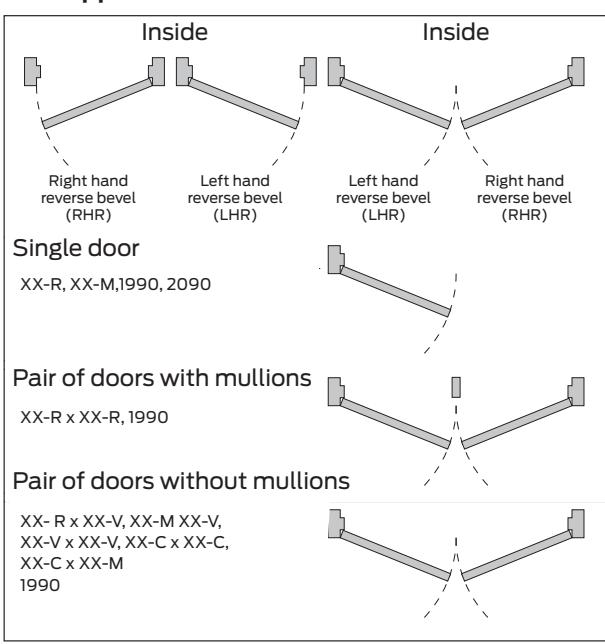
Device dimensions
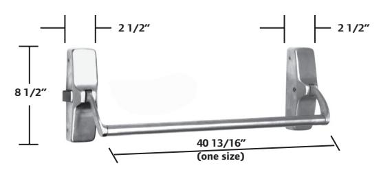
Product information and specifications contained in this catalog are subject to change without notice. Please consult the factory.
| Number | BHMA/ANSI function |
|---|---|
| 01 | Exit only, no trim |
| 02 | Entrance by trim when actuating bar is locked down |
| 03 | Entrance by trim when latchbolt is retracted by key; key removable only when locked |
| 04 | Entrance by trim when latchbolt is retracted by key or set in a retracted position by key |
| 08 | Entrance by knob or lever; key locks or unlocks knob or lever |
| 09 | Entrance by knob or lever only when released by keys; key removable only when locked |
Type and functions
XX Series
These pages list all functions available for the XX series devices. The XX-C devices use Delta trim only. See page 17.
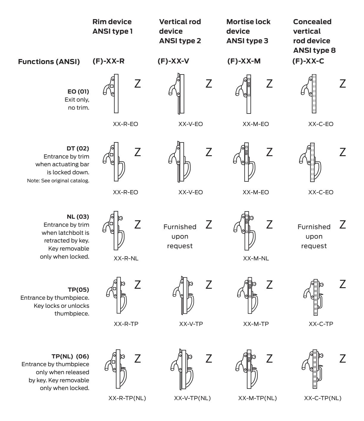
Z Fire exit hardware Use "F" prefix for fire exit hardware.
Type and functions
XX Series
These pages list all functions available for the XX Series devices. The XX-C devices use Delta trim only. See page 17.
|
Rim device
ANSI type 1 |
Vertical rod
device ANSI type 2 |
Mortise lock
device ANSI type 3 |
Concealed
vertical rod device ANSI type 8 |
|
|---|---|---|---|---|
| Functions (ANSI) | (F)-XX-R | (F)-XX-V | (F)-XX-M | (F)-XX-C |
|
L or K (08)
Entrance by knob or lever. Key locks or unlocks knob. |
Z
XX-R-L/K |
Z
XX-V-L/K |
Z
XX-M-L/K |
Z
XX-C-L/K |
|
L(NL) or K(NL) (09)
Entrance by knob or lever only when released by key. Key removable only when locked. |
Z
XX-R-L/K(NL) |
Z
XX-V-L/K(NL) |
Z
XX-M-L/K(NL) |
Z
XX-C-L/K(NL) |
|
TLP(NL) or TP(NL) (12)
Entrance by control turnpiece only when released by turning key. Key removable only when locked. |
Z
XX-V-TL(NL) |
Z
XX-C-TL or TLP (NL) |
Z Fire exit hardware Use "F" prefix for fire exit hardware.
How to order
XX Series
|
AE
F |
XX | V | L-DANE | US3 | 3' | LHR | LBR | SNB | WD | |||
|---|---|---|---|---|---|---|---|---|---|---|---|---|
| Rating | ||||||||||||
| F | Fire exit hardware | |||||||||||
| Blank | Panic exit hardware | |||||||||||
| Device series | ||||||||||||
| XX | Crossbar device | |||||||||||
| Device type | ||||||||||||
| R | Rim | C | Concealed vertical rod | |||||||||
| V | Surface vertical rod | C-WDC Concealed vertical rod | ||||||||||
| M | Mortise | wood door (90 min w/SCDC) | ||||||||||
| Trim function (see trim pages for all functions) | ||||||||||||
| EO | Exit only | |||||||||||
| DT | Dummy trim | K | Knob | |||||||||
| NL | Night latch | L | Lever (dane standard) | |||||||||
| C | Cylinder trim less pull | |||||||||||
| Latch option | ||||||||||||
| DL | Deadlocking | |||||||||||
| Finish | ||||||||||||
| US3 |
US10
US26 |
US32 | ||||||||||
| US4 |
SP313
US26D |
US32D | ||||||||||
| Door width | ||||||||||||
| – | Specify exact door width | |||||||||||
| Handing | ||||||||||||
| RHR | Right hand reverse | |||||||||||
| LHR | Left hand reverse | |||||||||||
| Less bottom rod | ||||||||||||
|
LBR
LBR-AFL |
Less bottom rod
LBR w/ auxiliary fire latch |
|||||||||||
| Other device options | ||||||||||||
| RCB | Reinforced crossbar | |||||||||||
| Accessories | ||||||||||||
| CYL | Cylinder | |||||||||||
| SNB | Sex bolts | AMS | All machine screws | |||||||||
| Other miscellaneous door information | ||||||||||||
| HMD | Hollow metal door | |||||||||||
| HMF | Hollow metal frame | |||||||||||
| WD | Wood door | |||||||||||
| WDF | Wood frame | |||||||||||
| ALD | Aluminum door | |||||||||||
| ALF | Aluminum frame | |||||||||||
| SCDC | Steel channel door construction | |||||||||||
| – | Specify other door or frame | |||||||||||
| – | Material information | |||||||||||
| – | Door height | |||||||||||
| – | Door thickness | |||||||||||
| – | Door undercut | |||||||||||
| – | Door label (20 min, 45 min, 90 min 1-1 | ⁄2 hr) | ||||||||||
| – | Stile width | |||||||||||
| – | Frame stop height | |||||||||||
| SGL | Single door | |||||||||||
| PR | Pair of doors swinging same direction | |||||||||||
| DE | Double egress doors |
1990/2090
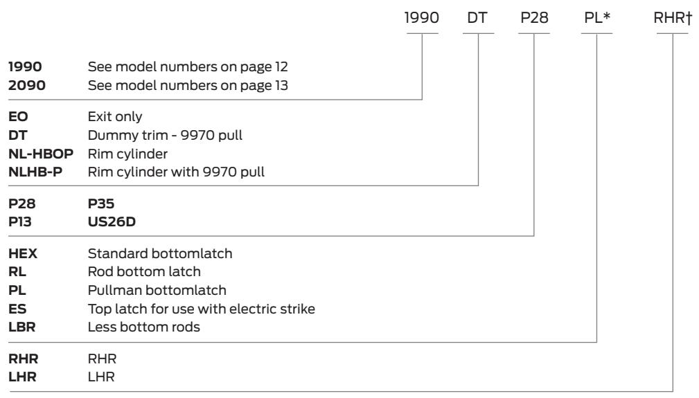
Note: Crossbar furnished 41" standard. Extra length crossbar 48" is available.
* Applies to 1990 only
† Applies to 2090 only
About Allegion
Allegion (NYSE: ALLE) is a global pioneer in safety and security, with leading brands like CISA®, Interflex®, LCN®, Schlage®, SimonsVoss® and Von Duprin®. Focusing on security around the door and adjacent areas, Allegion produces a range of solutions for homes, businesses, schools and other institutions. Allegion is a $2 billion company, with products sold in almost 130 countries.
For more, visit www.allegion.com