Falcon 24, 25 Exit Device Catalog
Open the original PDF document
View PDF

Table of contents
| 4 | Introducing the 24 Series and 25 Series | 28 | 24 Series trims |
| 6 | 25 Series rim devices | 29 | 24 Series finishes |
| 8 | 25 Series vertical rod devices | 30 | 24 Series types and functions |
| 10 | 25 Series mortise devices | 31 | 24 Series door application |
| 12 | 25 Series concealed vertical rod devices | 32 | Motorized electric latch retraction |
| 14 | 25 Series accessories | 34 | Delayed egress |
| 15 | 25 Series strikes | 36 | Electric lock/unlock trim |
| 16 | 25 Series trims | 37 | Exit alarm |
| 17 | 25 Series finishes | 38 | Device monitoring |
| 18 | 25 Series types and functions | 39 | Power supply |
| 19 | 25 Series door application | 40 | Electrical options summary |
| 20 | 24 Series rim devices | 41-43 | How to order |
| 22 | 24 Series vertical rod devices | ||
| 24 | 24 Series concealed vertical rod devices |
24 Series accessories
24 Series strikes
The Falcon® difference
Safety, security and uncompromising value
At Falcon®, we know that every product you sell not only has to meet local building codes, but also your expectations for performance and quality. We take your expectations seriously, and that's why we build our touchbars to deliver durability, convenience and unmatched value. After all, we've built our reputation on the same standards that you have – providing quality products at a reasonable price delivered on time. It's the way we do business and it's what makes Falcon exits a powerful choice no matter what your project.
The Falcon 24 and 25 Series
The perfectly simple, tougher than nails, costs less than you think, fits anywhere exit device.
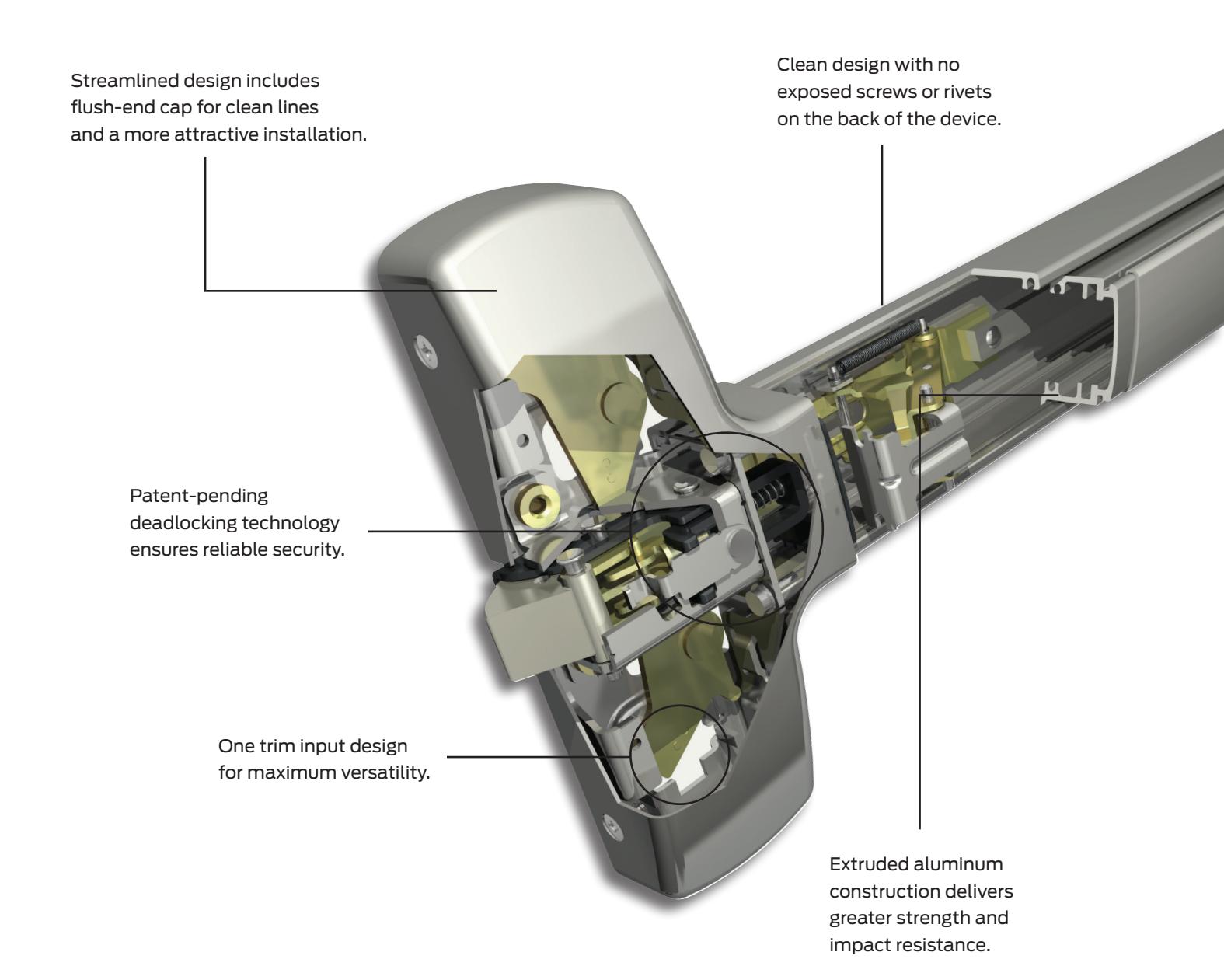
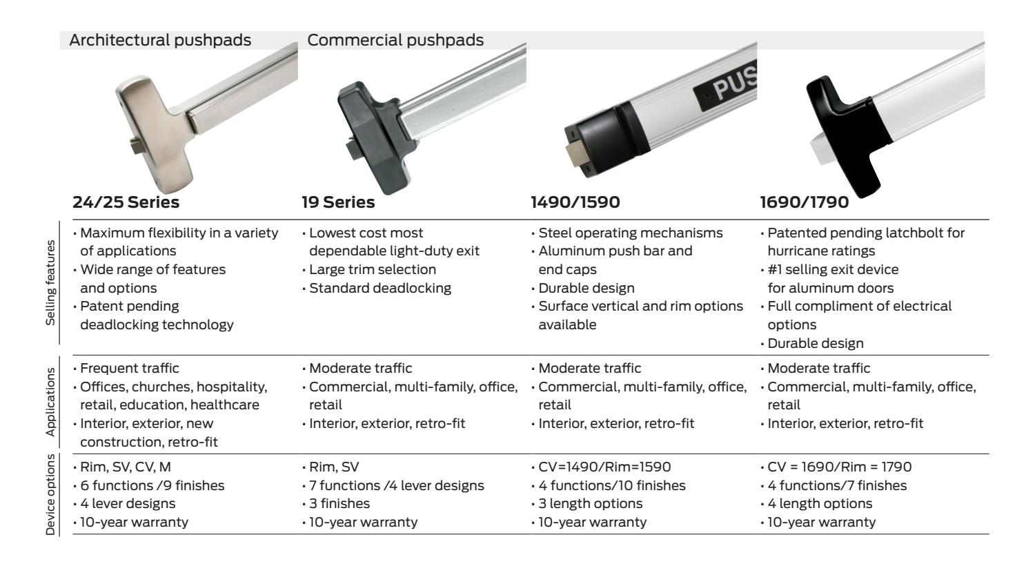
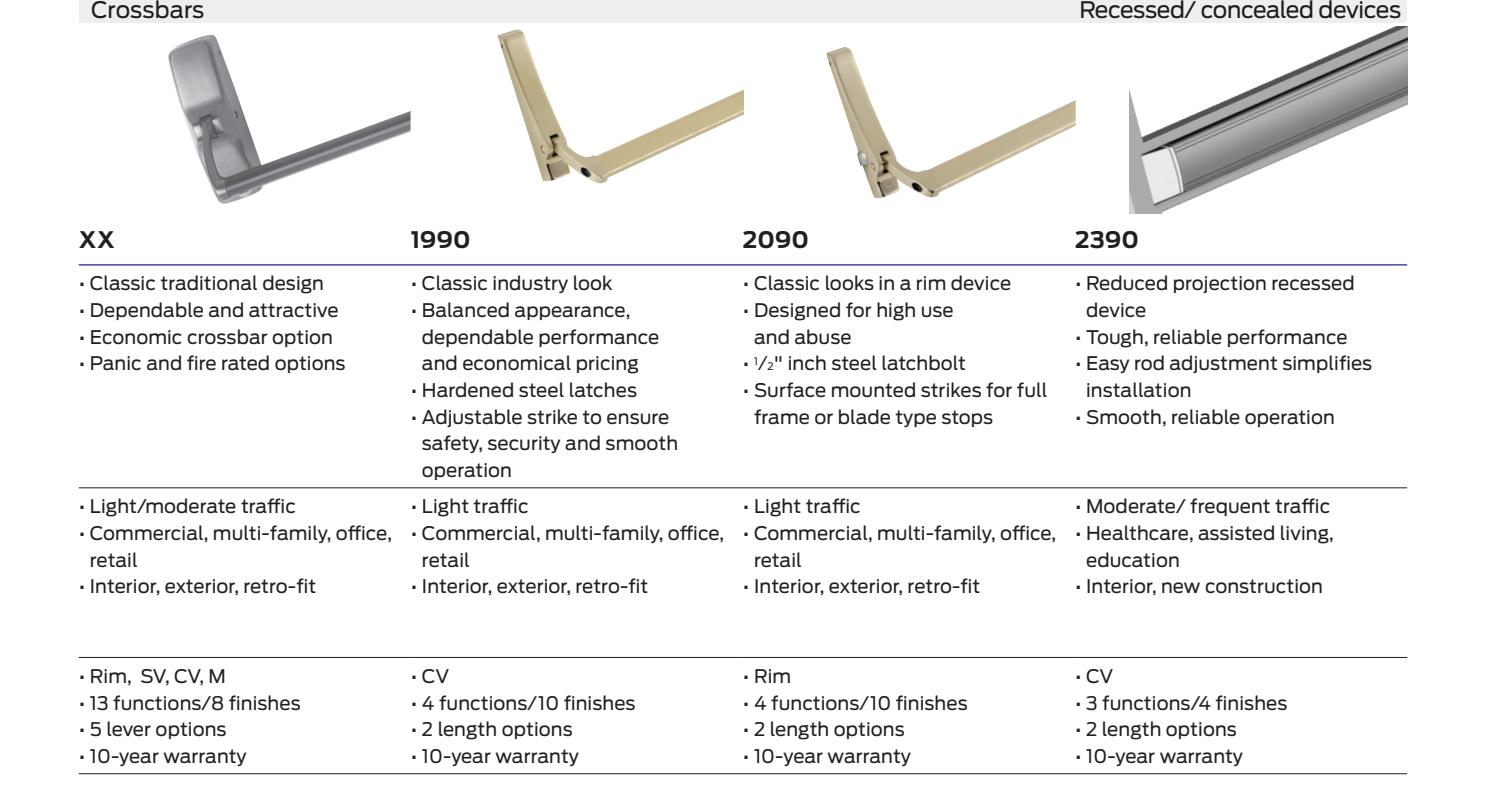
Offices, banks, assisted living facilities, retail stores and other commercial buildings have constant traffic, so door hardware must be able to take continual use and abuse. The Falcon 24 and 25 Series exit devices fill the bill with some of the toughest, most reliable performance in the business. A host of features makes this a smart solution, like a choice of an A or B label fire rating, electrified and panic options, and a full complement of trims. Sleek, streamlined styling and a choice of wide (25 Series) and narrow stile (24 Series) device applications means a smart solution for your building design, as well as its use. And since they're backed by one of the best names in the business, you can be sure you're getting the utmost value, reliability and durability.
Features
Falcon exit devices
25-R Series
Rim device
Panic exit hardware
The Falcon 25-R Series rim device meets the demanding requirements of high traffic installations with a single-point, rim type latch and a streamlined touch bar design. This device can also be electrified for maximum ease of use and accessibility.
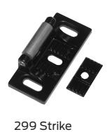
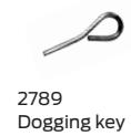
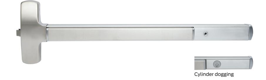
Single door application
| Device |
Door
size |
Door
strike |
Door stile
(in) |
Min door
opening width |
|---|---|---|---|---|
| 25-R | 3' |
299
264 1439 1606 |
4"
3 7 ⁄8" 3 1 ⁄4" 3 5⁄8" |
2' 7 1
⁄2" 2' 7 3⁄8" 2' 6 3⁄4" 2' 7 1 ⁄8" |
| 25-R | 4' |
299
264 1439 1606 |
4"
3 7 ⁄8" 3 1 ⁄4" 3 5⁄8" |
3' 1 1
⁄2" 3' 1 3⁄8" 3' 3⁄4" 3' 1 1 ⁄8" |
Double door application
| Device |
Door
size |
Strike x
mullion |
Door
stile (in) |
Min door
opening width |
|---|---|---|---|---|
| 25-R | 3' | 299 x 2923 |
4 1
⁄8" |
2' 7 1
⁄2" |
| 299 x 4023 | 4 3⁄8" |
2' 7 1
⁄2" |
||
| 264 x 2923 | 4" | 2' 7 3⁄8" | ||
| 264 x 4023 |
4 1
⁄4" |
2' 7 3⁄8" | ||
| 1439 x 2923 |
3 7
⁄8" |
2' 7 !
⁄4" |
||
| 1439 x 4023 |
4 1
⁄8" |
2' 7 1
⁄4" |
||
| 1606 x 2923 |
4 1
⁄4" |
2' 7 1
⁄8" |
||
| 1606 x 4023 |
4 1
⁄2 " |
2' 7 1
⁄8" |
||
| 25-R | 4' | 299 x 2923 |
4 1
⁄8" |
3' 1 1
⁄2" |
| 299 x 4023 | 4 3⁄8" |
3' 1 1
⁄2" |
||
| 264 x 2923 | 4" | 3' 1 3⁄8" | ||
| 264 x 4023 |
4 1
⁄4" |
3' 1 3⁄8" | ||
| 1439 x 2923 |
3 7
⁄8" |
3' 1 !
⁄4" |
||
| 1439 x 4023 |
4 1
⁄8" |
3' 1 1
⁄4" |
||
| 1606 x 2923 |
4 1
⁄4" |
3' 1 1
⁄8" |
||
| 1606 x 4023 |
4 1
⁄2 " |
3' 1 1
⁄8" |
||
| 25-Vx 25-R | 3' | 1609 |
3 1
⁄2" |
2' 7 5⁄8" for |
|
3 1
⁄2" Min stile |
||||
| 25-Vx 25-R | 4' | 1609 |
3 1
⁄2" |
3' 1 5⁄8" for |
|
3 1
⁄2" Min stile |
| Hand: | Non-handed |
| Finishes: |
US3 (605); US4 (606); US10 (612); US11 (643e); US15
(619); US19 (622); US26 (625); US26D (626); US32 (629); US32D (630); US28 (628), 313AN (710) (see page 17 for finishes) |
| Strikes: | 299 strike standard (see page 15 for additional info) |
| Latchbolt: | Stainless steel, 3⁄4" throw |
|
Deadlocking
latchbolt: |
Standard |
| Dogging feature: |
Half turn hex dogging standard. No threaded parts to
wear out. |
| Cylinder dogging: |
Specify "CD" prefix. Uses 1 1
⁄ 8" long mortise cylinder with standard cam. |
| Stock sizes: | See chart to left. Cut to size in the field. |
| Doors: |
1 3⁄4" thick, wood or metal. Specify thickness if other
than 1 3⁄4". |
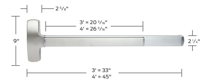
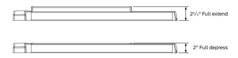
| Projections: | 2 3⁄4" maximum, 2" dogged. |
| Mounting height: |
40 1
⁄4" from CL to finished floor. |
| Electric functions: |
Can be interfaced with building security systems.
Motorized electric latch retraction (fail secure only), FSA/FSE trim, security monitoring, delayed egress and exit alarm available. |
| Fasteners: |
All mounting screws are concealed, sheet metal screws
and machine screws standard. |
| Sex bolts: |
Recommended when device is used with hollow core
wood, composite or light gauge hollow metal doors. For EO device, specify 8 - 425 (#I0-24) SNB. For devices with trim, specify 2 - 425 (#IO-24) SNB. |
| ANSI: | Certified ANSI A156.3-2001 grade 1 standards. |
|
Center case and
working parts: |
Center case is heavy wrought and sintered metal parts. |
| Shim kits: |
For glass lite applications; 1
⁄4" thick, specify SK25-RM. |
| 579 Strike retrofit kit: Consult factory. | |
F-25-R Series
Rim device
Z Fire exit hardware
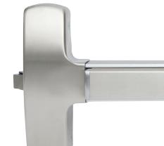
The Falcon F-25-R Series rim device combines sleek styling and durability with the protection of a fire-rated device. The F-25-R also features a single-point, rim type latch and can be electrified.
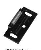
Single door application
| Device |
Door
size |
Door
strike |
Min
stile (in) |
Min door
opening width |
|---|---|---|---|---|
| F-25-R | 3' | 299-F | 4" |
2' 7 1
⁄2" |
| F-25-R | 4' | 299-F | 4" |
3' 1 1
⁄2" |
Double door application
| Device |
Door
size |
Door strike |
Min
stile (in) |
Min door
opening width |
|---|---|---|---|---|
| F-25-R | 3' | 499-F x F-4023 |
4 1
⁄2" |
2' 7 5⁄8" |
| F-25-R | 4' | 499-F x F-4023 |
4 1
⁄2" |
3' 1 5⁄8" |
| Hand: | Non-handed |
|---|---|
| UL: |
"A" label (3 hr.); 4'0" x 8'0"; 8'0" x 8'0" with
F-4023 mullion. |
|
"B" label (1 1
⁄2 hr.); 8'0" x 8'0"; with KRF4023. |
|
| Finishes: |
US3 (605); US4 (606); US10 (612); US11
(643e); US15 (619); US19 (622); US26 (625); US26D (626); US32 (629); US32D (630); US28 (628), 313AN (710) (see page 17 for finishes) |
| Strikes: |
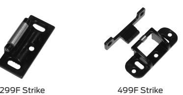
299F strike standard. 499F standard for pairs
with mullion. |
| Latchbolt: | Stainless steel, 3⁄4" throw |
|
Deadlocking
latchbolt: |
Standard |
| Stock sizes: | See chart to left. Cut to size in the field. |
| Doors: |
1 3⁄4" thick, wood or metal. Specify thickness if
other than 1 3⁄4". |
| Projections: | 2 3⁄4" maximum. |
| Mounting height: |
40 1
⁄4" from CL to finished floor. |
| Electric functions: |
Can be interfaced with building security
systems. Motorized electric latch retraction (fail secure only), FSA/FSE trim, security monitoring, delayed egress and exit alarm available. |
| Fasteners: |
All mounting screws are concealed, sheet metal
screws and machine screws standard. |
| Sex bolts: |
Required for use in EO applications when used
with wood, composite or non-reinforced hollow metal doors. For EO device, specify 8 - 425 (#10-24) SNB. For devices with trim, specify 2 - 425 (#10-24) SNB. |
| ANSI: | Certified ANSI A156.3-2001 grade 1 standards. |
|
Center case and
working parts: |
Center case is heavy wrought and sintered
metal parts. |
| Shim kits: |
For glass lite applications; 1
⁄4" thick, specify SK25-RM. |
25-V Series Vertical rod device
Panic exit hardware
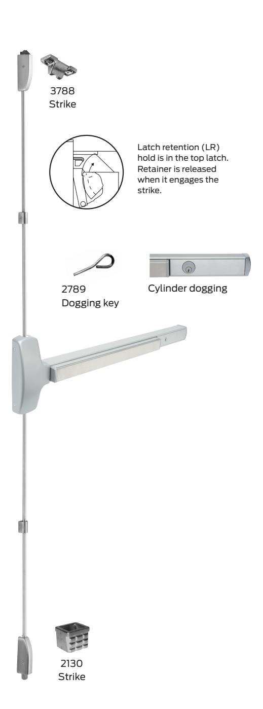
High-traffic applications demand the added strength and protection that comes with a vertical rod device. The Falcon F-25-V Series delivers with a surface-applied design that includes standard top latch and deadlocking. The sleek touch bar design ensures an attractive installation.
| Hand: | Field reversible. |
| Finishes: |
US3 (605); US4 (606); US10 (612); US11 (643e); US15
(619); US19 (622); US26 (625); US26D (626); US32 (629); US32D (630); US28 (628), 313AN (710) (see page 17 for finishes) |
| Strikes: |
3788 top strike is surface applied
2130 bottom strike is mortised into floor |
| Angle bracket |
Use 4215 angle bracket in flush transom installations
Allows use of standard 3788 strike |
| Latchbolt: |
Top stainless steel 3⁄4" throw. Bottom bolt, 1
⁄2" throw. |
| Deadlocking latchbolt: | Standard in top latch. |
| Dogging feature: |
Half turn hex dogging standard. No threaded parts to
wear out. |
| Cylinder dogging: |
Specify "CD" prefix. Uses 1 1
⁄ 8" long mortise cylinder with standard cam. |
| Stock sizes: | See chart to below. |
| Doors: |
1 3⁄4" thick, wood or metal. Specify thickness if other
than 1 3⁄4". |
| Projections: | 2 3⁄4" maximum, 2" dogged. |
| Stile : | See chart below. |
| Electric functions: |
Can be interfaced with building security systems.
Motorized electric latch retraction (fail secure only), FSA/FSE trim, security monitoring, delayed egress and exit alarm available. |
| Fasteners: |
All mounting screws are concealed, sheet metal screws
and machine screws available, specify AMS. |
| Sex bolts: |
Recommended when device is used with hollow core
wood, composite or light gauge hollow metal doors. For EO device, specify 12 - 425 (#10-24) SNB. For devices with trim, specify 8 - 425 (#10-24) SNB. |
| ANSI: | Certified ANSI A156.3-2001 grade 1 standards. |
| Vertical rods: |
Furnished to length based on a 40 1
⁄4" horizontal CL from finished floor and a 7'0" door standard. Variations from these standards must be specified when ordering. |
| 25-V-LBR: | Less bottom rod vertical device. |
| Shim kits: |
For glass lite applications; 1
⁄4" thick, specify SK25-V. |
| Device |
Door
size |
Door
strike |
Min
stile (in) |
Min door
opening width |
|---|---|---|---|---|
| 25-V | 3' | All |
3 1
⁄2" |
2' 7 1
⁄8" |
| 25-V | 4' | All |
3 1
⁄2" |
3' 1 1
⁄8" |
| 25-V x 25-R | 3' | 1609 |
3 1
⁄2" |
2' 7 5⁄8" for
3 1 ⁄2" Min. Stile |
| 25-V x 25-R | 4' | 1609 |
3 1
⁄2" |
2' 1 5⁄8" for
3 1 ⁄2" Min. Stile |
F-25-V Series
Vertical rod device
Z Fire exit hardware
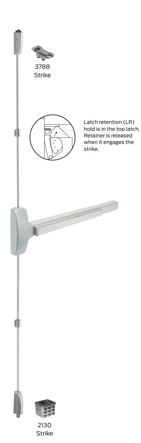
When your application requires strength and durability, plus fire rated performance, the F-25-V Series is the total package. This surface-applied vertical rod device includes a sleek touch bar design with top latch and deadlocking standard.
| Hand: | Field reversible. |
| UL: |
"A" Label (3 hr) - 8' x 10' double egress; 90 min. same
egress - 8' x 10' Wood door: 20 min. 8' x 10'; 90 min. 8' x 9'. Consult door manufacturer for maximum rating. |
| Finishes: |
US3 (605); US4 (606); US10 (612); US10B (613); US11
(643e); US15 (619); US19 (622); US26 (625); US26D (626); US32 (629); US32D (630), US28 (628), 313AN (710) (see page 17 for finishes) |
| Strikes: |
3788 top strike is surface applied.
2130 bottom strike is mortised into floor. |
| Latchbolt: |
Top stainless steel 3⁄4" throw. Bottom bolt, 1
⁄2" throw. |
| Deadlocking latchbolt: | Standard in top latch |
| Latch retention hold: | Standard with top latch |
| Stock sizes: | See chart below |
| Doors: |
1 3⁄4" thick, wood or metal. Specify thickness if other
than 1 3⁄4". |
| Projections: | 2 3⁄4" maximum. |
| Stile : | See chart below. |
| Electric functions: |
Can be interfaced with building security systems.
Motorized electric latch retraction (fail secure only), FSA/FSE trim, security monitoring, delayed egress and exit alarm available. |
| Fasteners: |
All mounting screws are concealed. All machine screws
(AMS) standard. |
| Sex bolts: |
Required when used with wood, composite or non
reinforced hollow metal doors. For EO device, specify 12 - 425 (#10-24) SNB. For devices with trim, specify 8 - 425 (#10-24) SNB. |
| ANSI: | Certified ANSI A156.3-2001 grade 1 standards. |
| F-25-V: |
Latch Retention (LR) top latch and bottom square bolt.
3788 strike top, 2130 flush strike bottom. |
| F-25-V-LBR: |
Less bottom rod vertical device. Auxiliary fire pin
required per pair. "A" Label (3 Hr) - 8' x 8'; 90 min. same egress - 8' x 8'. |
| Vertical rods: |
Furnished to length based on a 40 1
⁄4" horizontal CL from finished floor and a 7'0" door standard. Variations from these standards must be specified when ordering. |
| Shim kits: |
For glass lite applications; 1
⁄4" thick, specify SK25-V. |
| Device |
Door
size |
Door strike |
Min
stile (in) |
Min door
opening width |
|---|---|---|---|---|
| F-25-V | 3' | All | 3 1⁄2" |
2' 7 1
⁄8" |
| F-25-V | 4' | All |
3 1
⁄2" |
3' 1 1
⁄8" |
25-M Series Mortise device
Panic exit hardware
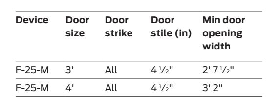
3'
4۱
25-M 25-M
The Falcon 25-M Series is the only device that pairs a tough, reliable exit device with our strongest mortise lock. The result is maximum safety and security in a single-point, mortise latch type device that also has an attractive touch bar design.
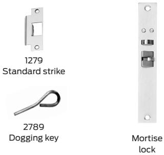
41/2"
41/2"
2'71/2"
3' 2"
All
All
| Hand: | Handed. |
|---|---|
| Finishes: | US3 (605); US4 (606); US10 (612); US11 (643e); US15 (619); US19 (622); US26 (625); US26D (626); US32 (629); US32D (630); US28 (628), 313AN (710) (see page 17 for finishes). |
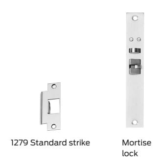
| Strikes: | 1279 standard, F1280 and 1281 optional. |
| Latchbolt: | 3 / 4 " throw. |
| Deadlocking latchbolt: | Standard. |
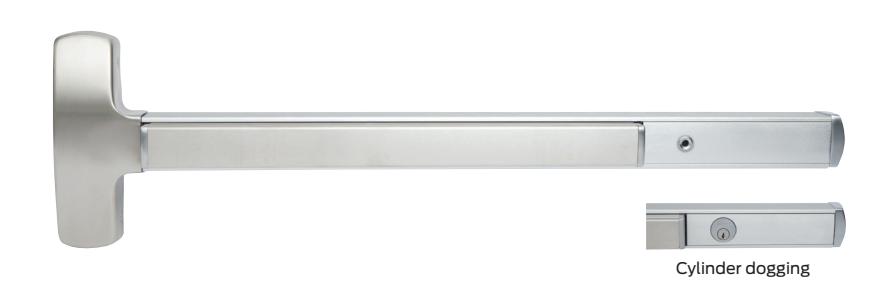
| Dogging feature: | Half turn hex dogging standard. No threaded parts to wear out. |
| Cylinder dogging: | Specify "CD" prefix. Uses 1 " mortise cylinder with standard cam. |
| Mounting height: | 40 / 4 " from CL to finished floor. For mortise lock prep per ANSI A115.1-1990. |
| Electric functions: | Can be interfaced with building security systems. Motorized electric latch retraction (fail secure only, not available with MEL), FSA/FSE trim, security monitoring, delayed egress and exit alarm available. |
| Stile: | 4 ½" minimum. |
| Projection: | 2 ³/₄" maximum, 2" dogged. |
| Stock Sizes: | See chart. |
| Doors: | "thick, wood or metal. Specify thickness if other than ". |
| Fasteners: | All mounting screws are concealed, sheet metal screws and machine screws standard. |
| Sex bolts: | Recommended when device is used with hollow core wood, composite or light gauge hollow metal doors. For EO device, specify 6 - 425 (#10-24) SNB. For devices with trim, specify 2 - 425 (#10-24) SNB. |
| ANSI: | Certified ANSI A156.3-2001 grade 1 standards. |
| Mortise lock: | Heavy wrought lock case with investment cast or sintered steel parts. Lock face is forged brass—fits standard cutout. Locks are designed to fit standard ANSI A115.1 preparation for 13/4" doors. Deadlocked when auxiliary bolt is depressed 5/16". |
| Shim kits: | For glass lite applications; 1/4" thick, specify SK25-RM. |
F-25-M Series
Mortise device
Z Fire exit hardware
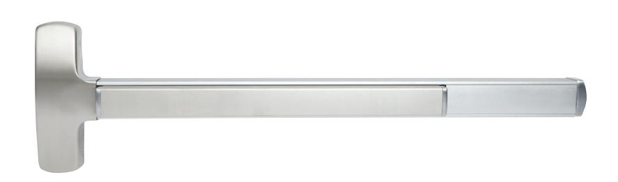
The Falcon F-25-M Series delivers the safety of a fire-rated exit device with a choice of ratings. The F-25-M can be paired with a Falcon mortise lock, assuring a tough and secure lock for any opening requiring a high level of safety and security.
| Hand: | Handed. |
|---|---|
| UL: |
"A" label (3 hr.); 4'0" x 10'0" single doors; 8'0" x
10'0" pair of doors (F-25-M x F-25-V or F-25-C). "B" label (1-1 ⁄2 hr) with F1280 open back strike. |
| Finishes: |
US3 (605); US4 (606); US10 (612); US11 (643e);
US15 (619); US19 (622); US26 (625); US26D (626); US32 (629); US32D (630); US28 (628), 313AN (710) (See page 17 for finishes.) |
| Strikes: |
1279 standard. F1280 optional, B label (1 1
⁄2 hr.). |
| Latchbolt: | Stainless steel, 3⁄4" throw. |
| Deadlocking latchbolt: | Standard. |
| Stock sizes | See chart. |
| Doors: |
1 3⁄4" thick, wood or metal. Specify thickness if other
than 1 3⁄4". |
| Projection: | 2 3⁄4" maximum. |
| Stile: |
4 1
⁄2" minimum. |
| Mounting height |
40 1
⁄4" from CL to finished floor. For mortise lock prep per ANSI A115.1-1990. |
| Electric functions: |
Can be interfaced with building security systems.
Motorized electric latch retraction (fail secure only, not available with MEL), FSA/FSE trim, security monitoring, delayed egress and exit alarm available. |
| Fasteners: |
All mounting screws are concealed. All machine
screws (AMS) standard. |
| Sex bolts: |
Required when used with wood, composite or
non-reinforced hollow metal doors. For EO device specify 6 - 425 (#10-24) SNB. For devices with trim, specify 2 - 425 (#10-24) SNB. |
| ANSI: | Certified ANSI A156.3-2001 grade 1 standards. |
| Mortise lock: |
Heavy wrought lock case with investment cast or
sintered steel parts. Lock face is forged brass—fits standard cutout. Locks are designed to fit standard ANSI A115.1 preparation for 1 3⁄4" doors. Deadlocked when auxilary bolt is depressed 5⁄16". |
| Shim kits: |
For glass lite applications; 1
⁄4" thick, specify SK25-RM. |
25-C Series
Concealed vertical rod device
Panic exit hardware
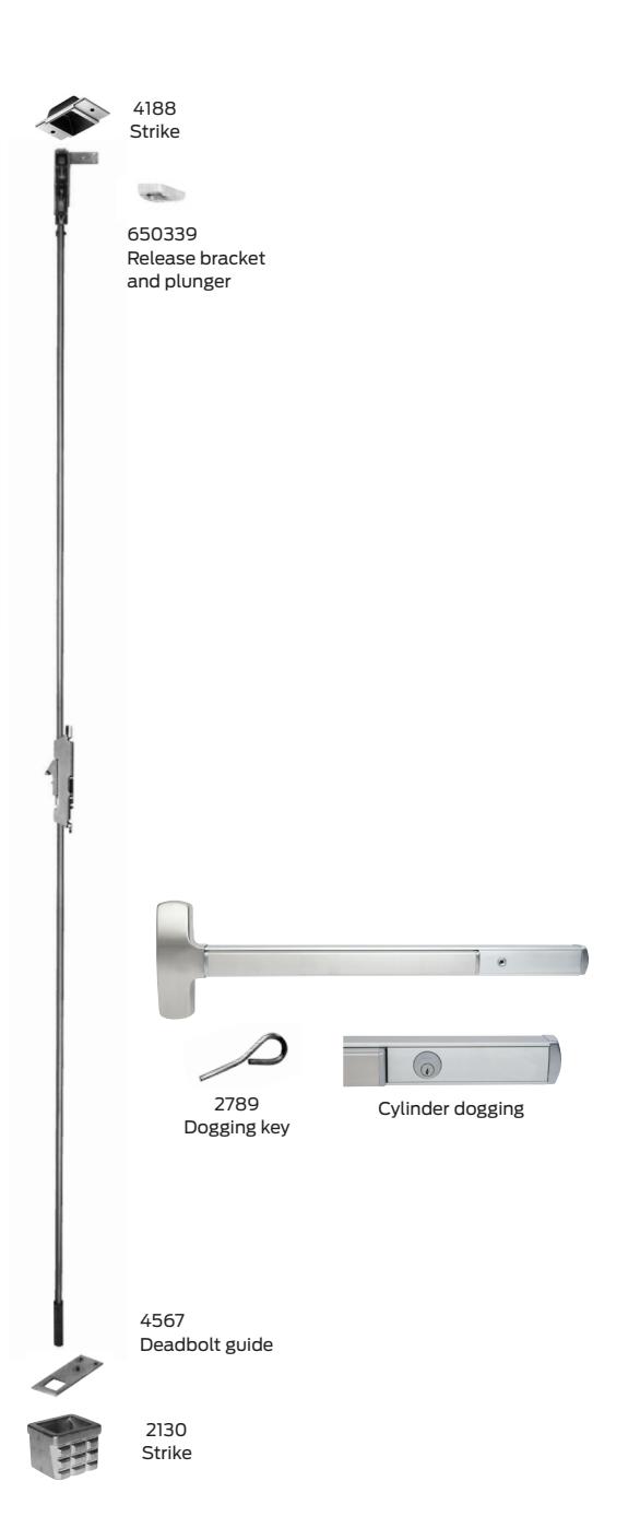
Concealed vertical rods add strength to the door, while maintaining an attractive appearance. The Falcon 25-C Series concealed vertical rod device offers great value, clean styling and the security benefits of two-point latching. Falcon's patented center slide mechanism allows easy rod adjustment in the field.
| Hand: | Field reversible. |
| Finishes: |
US3 (605); US4 (606); US10 (612); US11 (643e); US15
(619); US19 (622); US26 (625); US26D (626); US32 (629); US32D (630); US28 (628), 313AN (710) (see page 17 for finishes) |
| Strikes: | 4188 mortised top, 2130 bottom standard, 4155 |
| Latchbolt: |
Top stainless steel 3⁄4" throw. Bottom bolt 1
⁄2" throw. |
|
Deadlocking
latchbolt: |
Standard in top latch |
|
Latch retention
hold: |
Standard in top latch |
| Dogging feature: |
Half turn hex dogging standard. No threaded parts to
wear out. |
| Cylinder dogging: |
Specify "CD" prefix. Uses 1 1
⁄8" long mortise cylinder dogging with standard cam. |
| Stock sizes: | See chart. |
| Doors: |
1 3⁄4" thick wood or metal. Specify thickness if other
than 1 3⁄4". |
| Projection: | 2 3⁄4" maximum, 2" dogged. |
| Stile: |
3 1
⁄2" minimum (6 1 ⁄2" minimum on wood doors). |
| Electric functions: |
Can be interfaced with building security systems.
Motorized electric latch retraction (fail secure only), FSA/FSE trim, security monitoring, delayed egress and exit alarm available. |
| Fasteners: |
All mounting screws are concealed, sheet metal screws
standard, machine screws available, specify AMS. |
| Sex bolts: |
Recommended when device is used with hollow core
wood, composite or light gauge hollow metal doors. For EO device, specify 6 - 425 (#10-24) SNB. For devices with trim, specify 2 - 425 (#10-24) SNB. |
| ANSI: | Certified ANSI A156.3-2001 grade 1 standards. |
| 25-C-LBR: | Less bottom rod concealed vertical device. |
| Vertical rods: |
Furnished to length based on 40 1
⁄4" horizontal CL to finished floor and a 7'0" door. Variations from these standards must be specified when ordering. |
| Patented centerslide: | For ease of adjustment. |
| Shim kits: | Consult factory. |
| Device |
Door
size |
Door
strike |
Min
stile (in) |
Min door
opening width |
|---|---|---|---|---|
| 25-C | 3' | All |
3 1
⁄2" (6 1 ⁄2" for wood doors) |
2' 7 1
⁄8" |
| 25-C | 4' | All |
3 1
⁄2" (6 1 ⁄2" for wood doors) |
3' 1 1
⁄8" |
F-25-C Series
Concealed vertical rod device
Z Fire exit hardware
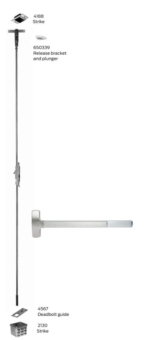
The Falcon F-25-C Series device lets you combine the safety of a fire-rated device with the clean aesthetics that come with a concealed vertical rod installation. In-field adjustment is simple thanks to our patented center slide mechanism. Two-point latching ensures optimal security at the door.
|
Field reversible
"A" label (3 hr.); 4'0" x 10'0" single doors; 8'0" x 10'0" pair of doors (F-25-M x F-25-V or F-25-C). US3 (605); US4 (606); US10 (612); US11 (643e); US15 (619); US19 (622); US26 (625); US26D (626); US32 (629); US32D (630); US28 (628), 313AN (710) (see page 17 for finishes). 4188 mortised top, 2130 bottom standard Stainless steel, 3⁄4" throw. Standard See chart 1 3⁄4" thick, wood or metal. Specify thickness if other than 1 3⁄4". 2 3⁄4" maximum 4" minimum 40 1 ⁄4" from CL to finished floor Can be interfaced with building security systems. Motorized electric latch retraction (fail secure only), FSA/FSE trim, security monitoring, delayed egress and exit alarm available. All mounting screws are concealed. All machine screws (AMS) standard. Required when used with wood, composite or non-reinforced hollow metal doors. For EO device |
||
|---|---|---|
|
specify 6 - 425 (#10-24) SNB. For devices with trim,
specify 2 - 425 (#10-24) SNB. |
||
| Certified ANSI A156.3-2001 grade 1 standards. | ||
| Less bottom rod, auxiliary fire pin required per pair | ||
|
Furnished to length based on 40 1
⁄4" horizontal CL to finished floor and a 7'0" door. Variations from these standards must be specified when ordering. |
||
| Consult factory | ||
|
Min
Min door strike stile (in) opening width |
||
|
4" (6 1
⁄2" for wood doors) 2' 7 1 ⁄8" |
||
25 Series
Accessories and options
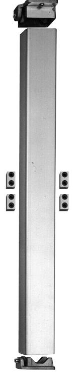
F-4023 Shown
Removable mullion
-
§ The 2923, F4023, 4023, KRF-4023 and KR-4023 steel mullions are for use with the 25-R devices on double door openings.
- Advantage: Increased security and tighter closure. Minimizes door warpage and sag. Regulates the flow of in-and-out traffic
- § Falcon removable mullions are easily removed and reinstalled for full width access
- § Rim devices are used on both leaves, attaining a perfectly symmetrical opening
- § The mullion assembly consists of a mullion, top and bottom mounting brackets and a screw pack
- § The F4023 and KRF-4023 fire-rated mullions also include four stabilizer blocks as required for labeled installations
- § Strikes are not furnished with the mullion. Please see page 15 for strike information
- § Mullions may be cut on the job for doors under stock lengths
- § KR Mullions require 1 1 ⁄4" mortise cylinder with standard A cam
Mullion features
- § Mullion fittings ductile iron
- § F4023, 4023, KRF-4023 and KR-4023 - 2" x 3" x height
- § 2923 mullion 1 1 ⁄2" x 2 1 ⁄2" x height
- § Prime coat only
- § 7' or 8' door opening standard, other door opening as specified
Cylinders
- § Cylinder supplied only when specified
- § Cylinders keyed different
Sex bolts
- § 325 (1 ⁄4"-20 thread)
- § 425 (#10-24 thread)
Dummy touch bars
- § Active and Inactive models only. Active model offered with RX or RX/KOR. Consult factory for details
- § To order, specify 250DT X finish, or 250DT X finish X active touch bar
(F)25-R Double door application
| Strike |
Installed
with mullion |
Min
stile |
B* |
|---|---|---|---|
| 299 | 2923 |
4 1
⁄8" |
3" |
| 299 | 4023 | 4 3⁄8" |
3 1
⁄4" |
| 499-F | F-4023 |
4 1
⁄2' |
3 5⁄16" |
| 264 | 2923 | 4" |
2 7
⁄8" |
| 264 | 4023 |
4 1
⁄4" |
3 1
⁄8" |
| 1439 | 2923 |
3 7
⁄8" |
2 3⁄4" |
| 1439 | 4023 |
4 1
⁄8" |
3" |
| 1606 | 2923 |
4 1
⁄4" |
2 5⁄8" |
| 1606 | 4023 |
4 1
⁄2" |
2 7
⁄8" |
| 1609 | Surface 25-V | 4" | 2 3⁄8" |
Cylinder reference
| Trim |
Standard
key cylinder |
IC key cylinder |
|---|---|---|
|
Cylinder
dogging |
985 - 1 1
⁄8" Mortise (#4 cam) |
C987 - 1 3⁄8" Mortise
#5 cam (Blocking ring plus sercurity collar must equal 1 ⁄4" thick) |
|
Cylinder only
(NL - OP) |
951- Rim cylinder | 953 - Rim cylinder |
|
Cylinder only
(NL - OP) |
* 986 - 1 1⁄4"
Mortise (#4 cam) |
** C987 - 1 3⁄8"
Mortise (#5 cam) |
| L, K, TP, NL |
986 - 1 1
⁄4" Mortise (#4 cam) |
C987 - 1 3⁄8"
Mortise (#5 cam) |
| 718C, 718NL |
986 - 1 1
⁄4" Mortise cylinder |
C987 - 1 3⁄8"
Mortise (#5 cam) (blocking ring plus security collar must equal 1 ⁄4") |
| N/A |
986 - 1 1
⁄4" Mortise (#4 cam) |
C987 (#5 cam, 1
⁄8" blocking ring) |
* Cylinder must be spaced off of the door a minimum of 1 ⁄4" via a recessed blocking ring

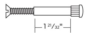
1 21⁄32"
** Cylinder must be spaced off of the door a minimum of 3 ⁄8" via a recessed blocking ring.
25 Series
Strikes and accessories
Strikes
For rim devices
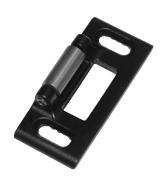
264 2 <sup>7</sup>/<sub>8</sub>" x 1 <sup>1</sup>/<sub>4</sub>" x <sup>9</sup>/<sub>16</sub>" (H x W x D) Panic device only.
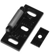
299 7 7/8" x 1 1/4" x 13/16" (H x W x D) Panic device only.
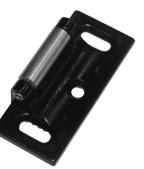
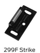
299F 2<sup>7</sup>/8" x 1 <sup>1</sup>/<sub>4</sub>" x <sup>13</sup>/<sub>16</sub>" (H x W x D)
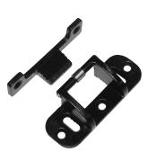
499F 3 <sup>5</sup>/8" x 1 <sup>1</sup>/<sub>2</sub>" x <sup>16</sup>/<sub>16</sub>" (H x W x D)
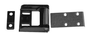
1439 Blade stop 1 <sup>3</sup>/<sub>4</sub>" x 1 <sup>7</sup>/<sub>8</sub>" x <sup>1</sup>/<sub>2</sub>" (H x W x D) Panic device only.
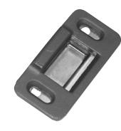
1606 2 <sup>7</sup>/8" x 1 <sup>3</sup>/8" x <sup>3</sup>/8" (H x W x D) Panic device only.
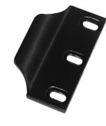
3 1/4" X 1 1/16" X 3/8" (H x W x D) Requires coordinator. Panic device only.
For surface and concealed vertical rod devices
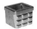
2130
(F)25-V and (F)25-C standard bottom strike for grouting into concrete or masonry floors.
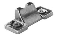
3788 Furnished top of (F)25-V.
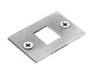
4155
Optional strike. Panic device only.
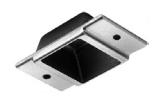
4188 Top strike for (F)25-C.
For mortise lock devices
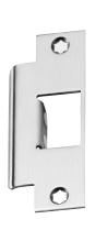
1279
Closed strike used on single doors and on fire exit hardware doors with coordinator.
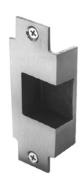
F1280
Open back strike used on pairs of " doors without astragal or coordinator. Can be used on stock hollow metal doors. F1280 "B" label stainless steel strike available.
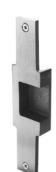
1281
Open back strike for " doors. 8" " face allow use in mortise lock cutout of stock hollow metal door.
Accessories
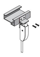
4215
Angle bracket for flush transom applications. Does not require elimination of latch retention feature. Accepts 3788 strike for 25-V device.
Surface vertical extension rods
Extension rods are available in 12", 24" and 36" lengths in all finishes. Both ends tapped and all-thread included as connector.
Concealed extension rods
Extension rods are available in 12", 24" and 36". Both ends have pressed-in, threaded inserts.
Filler Plates
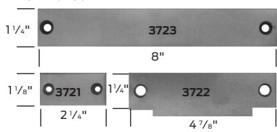
3721/3722/3723
Steel filler plates
3721 Cylindrical lock front filler
3722 Strike filler - set no. SC for 161 cutout
3723 Mortise lock front filler
3722 Strike filler - set no. SM for 86 cutout
25 Series Trim designs
Functionality built into the trim, facilitating easy door preps, easy field retrofit and easy ordering.
Lever trims (510L)
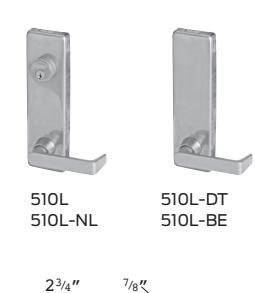
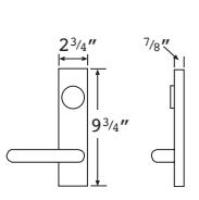
Lever designs
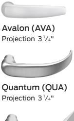
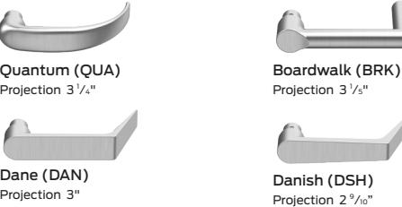
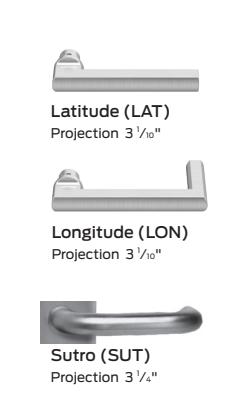
All levers return to within 1 ⁄2" of door. Escutcheon: 9 3 ⁄4" (H) x 2 3 ⁄4" (W) (specify handing) brass finish. Protected by easily replaceable shear pin.
Lever is reversible, supplied RHR if not specified. For keyed functions, see page 14 for cylinder requirements.
⁄5"
⁄10"
⁄5"
Broadway (BRW) Projection 3 1
Vandal - resistant lever trims (511L)
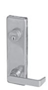
Provides resistance to rotation, making damage of trim due to attack from the outside less likely. Designed to operate normally after vandalism attempts without the need for maintenance personnel intervention.
- § Heavy duty, vandal-resistant, ANSI AI56.3 grade 1 security trim
- § Lever deflects up to 22 ft-lb for a minimum of 10,000 vandal-resistant cycles
- § Vandal resistance is present in both lever rotation directions
- § After lever is fully deflected, lever stops rotating and a shear pin breaks at 70 ft-lb to prevent damage to unit
- § Available on 25 rim, vertical, mortise, and concealed devices
- § Retrofits all existing 25 trim without additional door prep
- § Works with all electric lock and unlock functions
- § Available in all finishes and lever designs including Avalon, Boardwalk, Broadway, Dane, Danish, Latitude, Longitude, Sutro, and Quantum
Key retracts latch bolt. Cylinder sold separately (see page 14).
Cylinder only (NL-OP)
Pull trims (512)
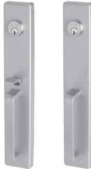
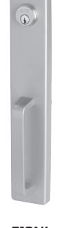
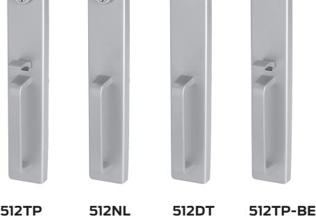
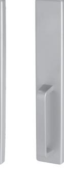
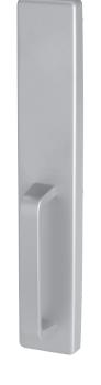
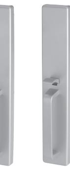
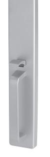
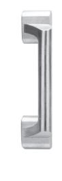
Delta (717)
717DT
Knob trims (513K)
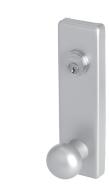
513K-DT 513K
Round ball knob 513K-BE 513K-NL
Escutcheon: 9 3⁄4" x 2 3⁄4" Projection: 4" Brass
For keyed functions, see page 14 for cylinder requirements.
Escutcheon: 16" x 2 3⁄4" Grip: 6 1 ⁄4" C- C Projection: 2 11⁄16" Brass
For keyed functions, see page 14 for cylinder requirements.
25 Series
Trim chart & finish chart
Function
| Lock/ unlock | NL | DT | BE | FSA/ FSE | |
|---|---|---|---|---|---|
| Lever (510) | 510L | 510L-NL | 510-DT | 510L-BE |
510L-FSA
510L-FSE |
|
Vandal-resistant
lever (511) |
511L | — | — | — |
511L-FSA
511L-FSE |
| Pull trims (512) | 512TP | 512-NL | 512DT | 512TP-BE |
512L-FSA
512L-FSE |
| Knob (513) | 513K | 513K-NL | 513K-DT | 513K-BE |
513L-FSA
513L-FSE |
| Delta (717) | — | — | 717DT | — | — |
25 Series finishes
| US number | BHMA number |
|---|---|
| US3 | 605 |
| US4 | 606 |
| US10 | 612 |
| US11 | 643e* |
| US15 | 619* |
| US19 | 622* |
| US26 | 625 |
| US26D | 626 |
| US28 | 628 |
| US32 | 629 |
| US32D | 630 |
| 313AN | 710 |
* Available on select devices and trims
25 Series Types and functions
This page shows all 25 Series device and trim functions.
|
Rim device
ANSI type 1 |
Vertical rod
device ANSI type 2 |
Mortise lock
device ANSI type 3 |
Concealed vertical
rod device ANSI type 8 |
|
|---|---|---|---|---|
| Functions (ANSI) | (F)-25-R | (F)-25-V | (F)-25-M | (F)-25-C |
|
EO (01)
Exit only, no trim. |
25-R-EO | 25-V-EO | 25-M-EO | 25-C-EO |
|
DT (02)
Entrance by trim when actuating bar is locked down. |
||||
| 25-R-DT | 25-V-DT | 25-M-DT | 25-C-DT | |
|
NL (03)
Entrance by trim when latchbolt is retracted by key. Key removable only when locked. |
||||
| 25-R-NL | 25-V-NL | 25-M-NL | 25-C-NL | |
|
TP (05)
Entrance by thumbpiece. Key locks or unlocks |
||||
| thumbpiece. | 25-R-TP | 25-V-TP | 25-M-TP | 25-C-TP |
|
L or K (08)
Entrance by knob or lever. Key locks or unlocks knob. |
||||
| 25-R-L/K | 25-V-L/K | 25-M-L/K | 25-C-L/K | |
|
L(NL) or K(NL) (03)
Entrance by knob or lever when latchbolt is retracted by key. Lever/knob is rigid. Key removable only |
||||
| when locked. | 25-R-L/K(NL) | 25-V-L/K(NL) | 25-M-L/K(NL) | 25-C-L/K(NL) |
25 Series Door application
Label doors
Models F-25-R, F-25-M, F-25-C and F-25-V are labeled for use as <sup>®</sup> Fire exit hardware.
Door thickness
All devices and components supplied for 13/4" doors standard. Specify door thickness if other than 13/4".
Door application chart
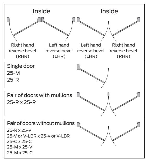
Product information and specifications contained in this catalog are subject to change without notice. Please consult the factory.
24-R Series
Rim device
Panic exit hardware
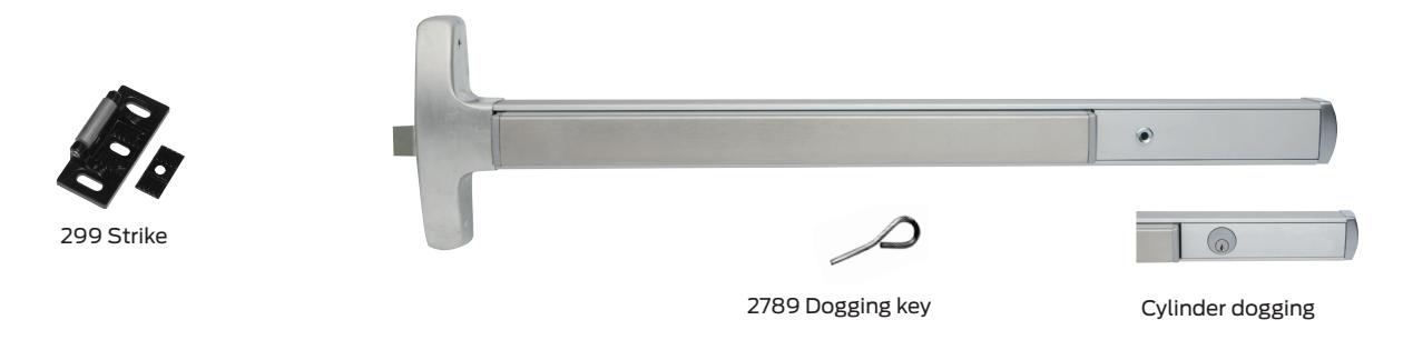
The Falcon 24-R Series narrow stile rim device allows for application versatility in high-traffic installations. Standard features include a single-point, rim type latch and a streamlined touch bar design. This device can also be electrified for maximum ease of use and accessibility.
Single door application
| Device |
Door
size |
Door
strike |
Min
stile (in) |
Min door
opening width |
|---|---|---|---|---|
| 24-R | 3' | 299 |
3 1
⁄2" |
2' 7 1
⁄2" |
| 264 | 3 3⁄8" | 2' 7 3⁄8" | ||
| 1439 |
2 1
⁄4" |
2'6 3⁄4" | ||
| 1606 | 2 3⁄4" |
2' 7 1
⁄8" |
||
| 24-R | 4' | 299 |
3 1
⁄2" |
3' 1 1
⁄2" |
| 264 | 3 3⁄8" | 3' 1 3⁄8" | ||
| 1439 |
2 1
⁄4" |
3' 3⁄4" | ||
| 1606 | 2 3⁄4" |
3' 1 1
⁄8" |
Double door application
| Device |
Door
size |
Door strike |
Min
stile (in) |
Min door
opening width |
|---|---|---|---|---|
| 24-R | 3' | 299 x 2923 |
3 1
⁄2" |
2' 7 1
⁄2" |
| 299 x 4023 | 4" |
2' 7 1
⁄2" |
||
| 264 x 2923 | 3 3⁄8" | 2' 7 3⁄8" | ||
| 264 x 4023 | 3 5⁄8" | 2' 7 3⁄8" | ||
| 1439 x 2923 |
3 1
⁄2" |
2' 7 1
⁄8" |
||
| 1439 x 4023 | 3 3⁄4" |
2' 7 1
⁄8" |
||
| 1606 x 2923 |
3 1
⁄2" |
2' 7 1
⁄8" |
||
| 1606 x 4023 | 3 3⁄4" |
2' 7 1
⁄8" |
||
| 4396 x 4423 |
2 1
⁄8" |
2' 6 5⁄8" | ||
| 24-R | 4' | 299 x 2923 |
3 1
⁄2" |
3' 1 1
⁄2" |
| 299 x 4023 | 4" |
3' 1 1
⁄2" |
||
| 264 x 2923 | 3 3⁄8" | 3' 1 3⁄8" | ||
| 264 x 4023 | 3 5⁄8" | 3' 1 3⁄8" | ||
| 1439 x 2923 |
3 1
⁄2" |
3' 1 1
⁄8" |
||
| 1439 x 4023 | 3 3⁄4" |
3' 1 1
⁄8" |
||
| 1606 x 2923 |
3 1
⁄2" |
3' 1 1
⁄8" |
||
| 1606 x 4023 | 3 3⁄4" |
3' 1 1
⁄2" |
||
| 4396 x 4423 |
2 1
⁄8" |
3' 5⁄8" |
| Hand: | Non-handed |
| Functions: |
24-EO (exit only) has all functions built in. Order
trim with the device, or add it later (see trim selection chart on page 29). |
| Finishes: |
US3 (605); US4 (606); US10 (612); US11
(643e); US15 (619); US19 (622); US26 (625); US26D (626); US32 (629); US32D (630); US28 (628), 313AN (710) (see page 29 for finishes) |
| Strikes: |
299F strike standard. See page 27 for optional
strikes. |
| Latchbolt: | Stainless steel, 3⁄4" throw. |
| Deadlocking latchbolt: | Optional. Specify "DL" prefix. |
| Dogging feature: |
Half turn hex dogging standard. No threaded
parts to wear out. |
| Stock sizes: | See chart to left. |
| Doors: |
1 3⁄4" thick, wood or metal. Specify thickness if
other than 1 3⁄4". |
| Projections: | 2 3⁄4" maximum, 2" dogged. |
| Mounting height: | 40" from CL to finished floor. |
| Electric functions: |
Can be interfaced with building security
systems. Motorized electric latch retraction (fail secure only), security monitoring, delayed egress and exit alarm available. |
| Fasteners: | All mounting screws are concealed. |
| Sex bolts: |
Recommended when device is used with hollow
core wood, composite or light gauge hollow metal doors. For EO device, specify 4 - 425 (#I0-24) SNB and 2 - 325 (1 ⁄4"-20) SNB. For devices with trim, specify 4 - 425 (#I0-24) SNB. |
| ANSI: | Certified ANSI A156.3-2001 grade 1 standards. |
|
Center case & working
parts: |
Wrought steel with heavy wrought and sintered
metal parts. |
| Shim kits: |
For glass lite applications; 1
⁄4" thick, specify SK24-R. |
F-24-R Series
Rim device
Z Fire exit hardware
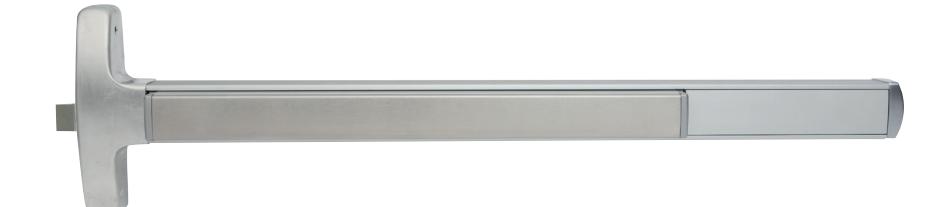
The Falcon F-24-R Series rim device combines sleek styling and durability with the protection of a fire-rated device. A narrow stile design allows for installation versatility. The F-24-R also features a single-point, rim type latch and can be electrified.
Single door application
| Device |
Door
size |
Door
strike |
Min
stile (in) |
Min door
opening width |
|---|---|---|---|---|
| F-24-R | 3' | 299-F |
3 1
⁄2" |
2' 7 1
⁄2" |
| F-24-R | 4' | 299-F |
3 1
⁄2" |
3' 1 1
⁄2" |
Double door application
|
F-24-R
3' |
299-F x F-4023 | 4" |
2' 7 1
⁄2" |
|
F-24-R
4' |
299-F x F-4023 | 4" |
3' 1 1
⁄2" |
| Hand: | Non-handed |
|---|---|
| UL: |
"B" label (1 1
⁄2 hr.); 4'0" x 8'0". |
| Functions |
F-24-REO (Exit only) has all functions built in.
Order trim with the device, or add it later. (see trim selection chart on page 29) |
| Finishes: |
US3 (605); US4 (606); US10 (612); US11
(643e); US15 (619); US19 (622); US26 (625); US26D (626); US32 (629); US32D (630); US28 (628), 313AN (710) (see page 29 for finishes) |
| Strikes: | 299F strike standard. |
| Latchbolt: | Stainless steel, 3⁄4" throw. |
| Deadlocking latchbolt: | Standard. |
| Stock sizes: | See chart to left. |
| Doors: |
1 3⁄4" thick, wood or metal. Specify thickness
if other than 1 3⁄4". |
| Projections: | 2 3⁄4" maximum. |
| Mounting height: | 40" from CL to finished floor. |
| Electric functions: |
Can be interfaced with building security
systems. Motorized electric latch retraction (fail secure only), security monitoring, delayed egress and exit alarm available. |
| Fasteners: |
All mounting screws are concealed. Furnished
with all machine screws. |
| Sex bolts: |
Required when used with wood, composite or
non-reinforced hollow metal doors. For EO device, specify 4 - 425 (#10-24) SNB and 2 - 325 (1 ⁄4"-20) SNB. For devices with trim, specify 4 - 425 (#10-24) SNB. |
| ANSI: |
Certified ANSI A156.3-2001 grade 1 stan
dards. |
|
Center case & working
parts: |
Investment-cast ferrous alloy with heavy
wrought and sintered metal parts. |
| Shim kits: |
For glass lite applications; 1
⁄4" thick, specify SK24-R. |
24-V Series Vertical rod device
Panic exit hardware
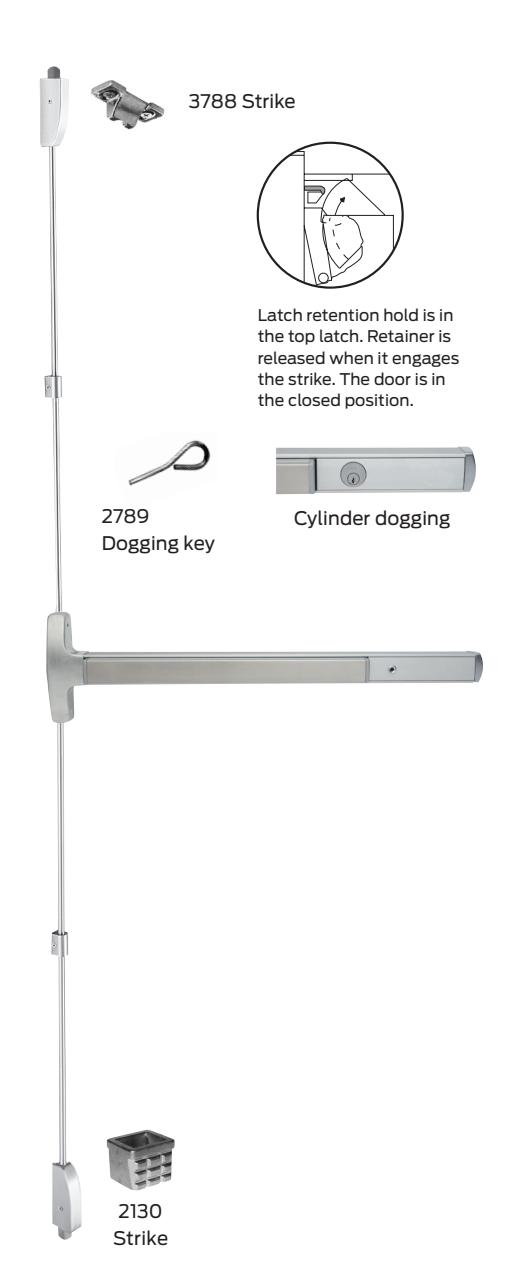
High-traffic applications demand the added strength and protection that comes with a vertical rod device. The Falcon 24-V Series delivers with a surface-applied design that includes standard top latch and deadlocking. The narrow stile and sleek touch bar design ensure an attractive installation.
| 24-V-EO (exit only) has all functions built in. Order trim with |
|---|
| the device, or add it later. (see trim selection chart on page 29) |
|
US3 (605); US4 (606); US10 (612); US11 (643e); US15 (619);
US19 (622); US26 (625); US26D (626); US32 (629); US32D (630); US28 (628), 313AN (710) (see page 29 for finishes) |
| 3788 top strike is surface applied, 2130 bottom strike is |
| Use 4215 angle bracket in flush transom installations. Allow |
|
Top stainless steel, top latch 3⁄4" throw, bottom bolt 1
⁄2" throw. |
| Standard with top latch. On top latch. |
| Half turn hex dogging standard. No threaded parts to wear out. |
| 1 3⁄4" thick, wood or metal. Specify thickness if other than 1 3⁄4" |
| ⁄8" minimum when used in pairs. |
|
Can be interfaced with building security systems. Motorized
electric latch retraction (fail secure only), security monitoring, delayed egress and exit alarm available. |
|
All mounting screws are concealed, sheet metal screws
standard, machine screws available, specify AMS. |
|
Recommended when device is used with hollow core wood,
composite or light gauge hollow metal doors. For EO device, specify 8 - 425 (#10-24) SNB and 2 - 325 (1 ⁄4"-20) SNB. For devices with trim, specify 8 - 425 (#10-24) SNB. |
| Certified ANSI A156.3-2001 grade 1 standards. |
|
Latch retention (LR) top latch and bottom square bolt. 3788
strike top, 2130 flush strike bottom. |
|
Furnished to length based on a 40" horizontal CL from finished
floor and a 7'0" door standard. Variations from these standards must be specified when ordering. |
| ⁄4" thick, specify SK24-V. |
| Device | Door size |
Door
strike |
Min
stile (in) |
Min door
opening width |
|---|---|---|---|---|
| 24-V | 3' | All |
2 1
⁄8" |
2' 7 1
⁄4" |
| 24-V | 4' | All |
2 1
⁄8" |
3' 1 1
⁄4" |
F-24-V Series
Vertical rod device
Z Fire exit hardware
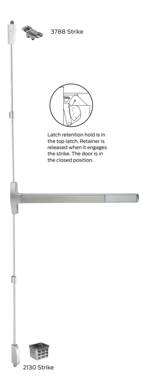
When your application requires strength and durability, plus fire-rated performance, the F-24-V Series is the total package. This surface-applied vertical rod device includes a sleek touch bar design with top latch and deadlocking standard, as well as a narrow stile that fits where you need it to.
| Hand: | Field reversible. |
|---|---|
| UL: |
"A" Label (3 hr) - double egress - 8' x 10'; 90 min. same egress
- 8' x 10'. Wood door: 20 min. 8' x 10'; 90 min. 8' x 9'. Consult door manufacturer for maximum rating. |
| Functions: |
F-24-V-EO (exit only) has all functions built in. Order trim with
the device, or add it later (see trim selection chart on page 29). |
| Finishes: |
US3 (605); US4 (606); US10 (612); US11 (643e); US15 (619);
US19 (622); US26 (625); US26D (626); US32 (629); US32D (630); US28 (628), 313AN (710) (see page 29 for finishes) |
| Strikes: |
3788 top strikes are surface applied, 2130 bottom strike is
mortised into floor. |
| Latchbolt: |
Top stainless steel, top latch 3⁄4" throw, bottom bolt 1
⁄2" throw. |
| Latch retention hold: | Standard with top latch. |
| Deadlocking latchbolt: | Standard with top latch. |
| Stock sizes: | See chart below. |
| Doors: |
1 3⁄4" thick, wood or metal. Specify thickness if other than
1 3⁄4" thick. |
| Projections: | 2 3⁄4" maximum. |
| Stile: |
2 1
⁄8" minimum when used in pairs. |
| Electric functions: |
Can be interfaced with building security systems. Motorized
electric latch retraction (fail secure only), security monitoring, delayed egress and exit alarm available. |
| Fasteners: |
All mounting screws are concealed. All machine (AMS)
standard. |
| Sex bolts: |
Recommended when device is used with hollow core wood,
composite or light gauge hollow metal doors. For EO device, specify 8 - 425 (#10-24) SNB and 2 - 325 (1 ⁄4-20) SNB. For devices with trim, specify 8 - 425 (#10-24) SNB. |
| ANSI: | Certified ANSI A156.3-2001 grade 1 standards. |
| F-24-V: |
Latch retention (LR) top latch and bottom square bolt. 3788
strike top, 2130 flush strike bottom. |
| F-24-V-LBR: |
Less bottom rod vertical device. Auxiliary fire pin required per
pair. "A" Label (3 hr) - 8' x 8'; 90 min. same egress - 8' x 8'. Wood Door: 20 minute minimum - 8' x 8' openings. Consult door manufacturer for maximum rating. |
| Vertical rods: |
Furnished to length based on a 40" horizontal CL from
finished floor and a 7'0" door standard. Variations from these standards must be specified when ordering. |
| Shim kits: |
For glass lite applications; 1
⁄4" thick, specify SK24-V. |
| Device | Door size |
Door
strike |
Min
stile (in) |
Min door
opening width |
|---|---|---|---|---|
| F-24-V | 3' | All |
2 1
⁄8" |
2' 7 1
⁄4" |
| F-24-V | 4' | All |
2 1
⁄8" |
3' 1 1
⁄4" |
24-C Series Concealed vertical rod device
Panic exit hardware
Concealed vertical rods add strength to the door, while maintaining an attractive appearance. The Falcon 24-C Series concealed vertical rod device offers great value, clean styling, a versatile narrow stile design and the security benefits of two-point latching. Falcon's patented center slide mechanism allows easy rod adjustment in the field.
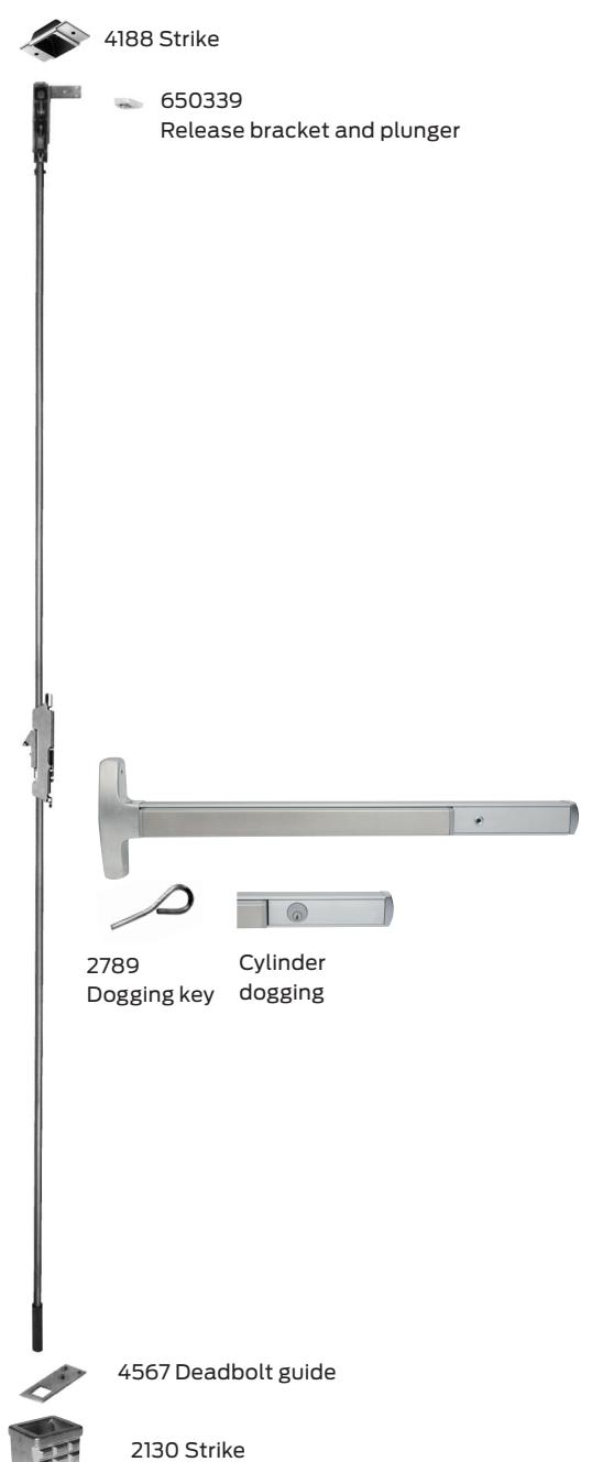
| Hand: | Field reversible or specify handing. |
| Functions: | See trim selection chart on page 29. Delta trim only. |
| Finishes: |
US3 (605); US4 (606); US10 (612); US11 (643e); US15
(619); US19 (622); US26 (625); US26D (626); US32 (629); US32D (630); US28 (628), 313AN (710) (see page 29 for finishes). |
| Strikes: |
4188 mortised top and 2130 flush strike bottom, optional
bottom 2126A and 4155. |
| Latchbolt: |
Top stainless steel, top latch 3⁄4" throw. Bottom bolt 1
⁄2" throw. |
| Deadlocking latchbolt: | Standard with top latch. |
| Latch retention hold: | Standard with top latch. |
| Dogging feature: |
Half turn hex dogging standard. No threaded parts to wear
out. |
| Cylinder dogging: |
Specify "CD" prefix. Uses 1 1
⁄8" long mortise cylinder dogging with standard cam. |
| Stock sizes: | See chart below. |
| Doors: | 1 3⁄4" thick, wood or metal. Specify if other than 1 3⁄4" thick. |
| Projections: | 2 3⁄4" maximum, 2" dogged. |
| Stile: |
2 1
⁄4" minimum when used in pairs. (6" minimum on wood doors) |
| Electric functions: |
Can be interfaced with building security systems. Motorized
electric latch retraction (fail secure only), security monitoring, delayed egress and exit alarm available. |
| Fasteners: |
All mounting screws are concealed, sheet metal screws
standard, machine screws available, specify AMS. |
| Sex bolts: |
Recommended when device is used with hollow core wood,
composite or light gauge hollow metal doors. For EO device, specify 2 - 425 (#10-24) SNB and 2 - 325 (1 ⁄4-20) SNB. For devices with trim, specify 2 - 425 (#10-24) SNB. |
| ANSI: | Certified ANSI A156.3-2001 grade 1 standards. |
| 24-V-LBR: | Less bottom rod concealed vertical device. |
| Vertical rods: |
Furnished to length based on 40" horizontal CL to finished
floor and a 7'0" door. Variations from these standards must be specified when ordering. |
| Patented centerslide: | For ease of adjustment. |
| Device | Door size |
Door
strike |
Min
stile (in) |
Min door
opening width |
|---|---|---|---|---|
| 24-C | 3' | All |
2 1
⁄4" (6" for wood doors) |
2' 7 3⁄8" |
| 24-C | 4' | All |
2 1
⁄4" (6" for wood doors) |
3' 1 3⁄8" |
F-24-C Series Concealed Vertical Rod Device
Z Fire Exit Hardware
The Falcon F-24-C Series device lets you combine the safety of a fire-rated device with the clean aesthetics that come with a narrow stile and concealed vertical rod installation. In-field adjustment is simple thanks to our patented center slide mechanism. Two-point latching ensures optimal security at the door.
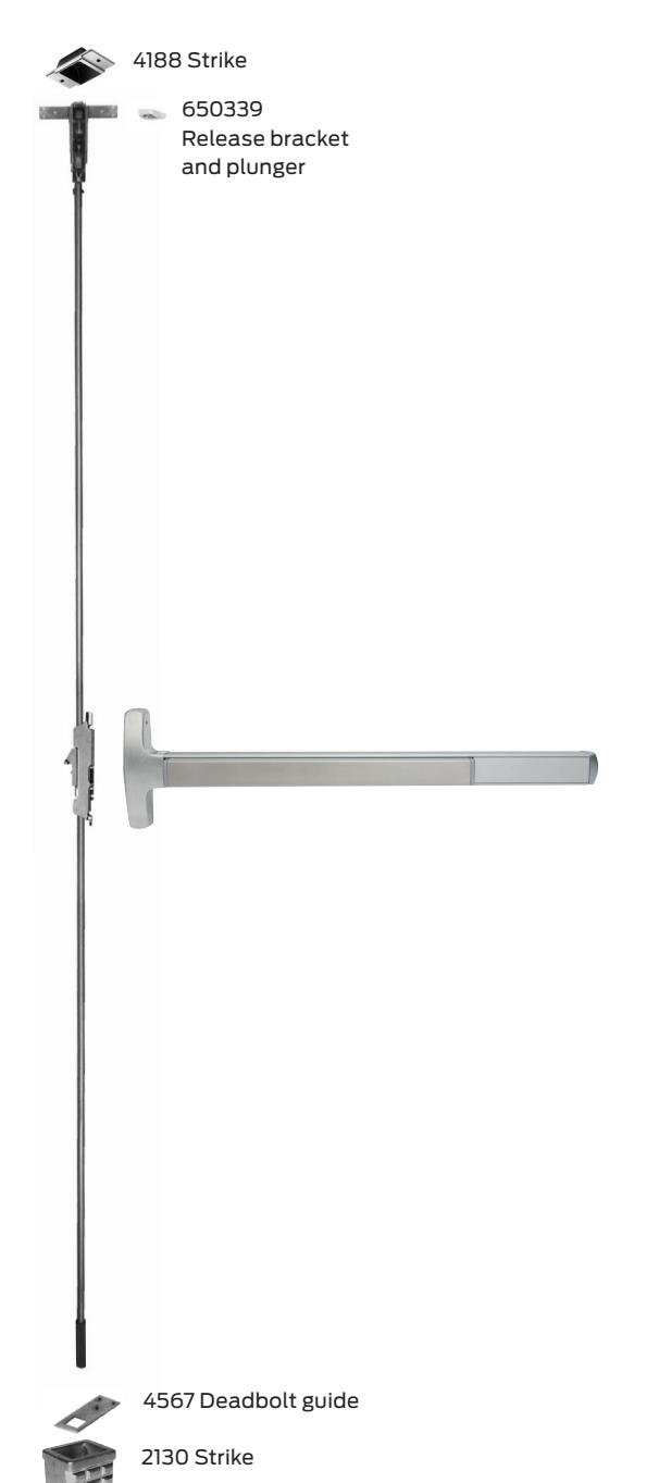
| Hand: | Field reversible. | ||||||
| UL: |
"A" Label (3 hr) - double egress - 8' x 10' ; 90 min. same
egress - 8' x 10'. |
||||||
| Functions: | See trim selection chart on page 29. Delta trim only. | ||||||
| Finishes: |
US3 (605); US4 (606); US10 (612); US11 (643e); US15
(619); US19 (622); US26 (625); US26D (626); US32 (629); US32D (630); US28 (628), 313AN (710) (see page 29 for finishes). |
||||||
| Strikes: | 4188 mortised top, 2130 flush strike bottom. | ||||||
| Latchbolt: | Top stainless steel, 3⁄4" throw. Bottom bolt 1 | ⁄2" throw. | |||||
| Latch retention hold: | Standard with top latch. | ||||||
| Deadlocking latchbolt: | Standard with top latch. | ||||||
| Stock sizes: | See chart below. | ||||||
| Doors: | 1 3⁄4" thick metal. Specify if other than 1 3⁄4" thick. | ||||||
| Projections: | 2 3⁄4" maximum. | ||||||
| Stile: |
3 5⁄8" minimum when used in pairs. (6" minimum on
wood doors) |
||||||
| Electric functions: |
Can be interfaced with building security systems.
Motorized electric latch retraction (fail secure only), security monitoring, delayed egress and exit alarm available. |
||||||
| Fasteners: | standard. | All mounting screws are concealed. All machine screws | |||||
| Sex bolts: |
Required when used with wood, composite or
non-reinforced hollow metal doors. For EO device specify 2 - 425 (#10-24) SNB and 2 - 325 (1 ⁄4"-20) SNB. For devices with trim, specify 2 - 425 (#10-24) SNB. |
||||||
| ANSI: | Certified ANSI A156.3-2001 grade 1 standards. | ||||||
| F-24-C-LBR |
Less bottom rod concealed vertical device. Auxiliary fire
pin required per pair. "A" Label (3 hr) - 8' x 8'; 90 min. same egress - 8' x 8'. |
||||||
| Vertical rods: |
Furnished to length based on 40" horizontal CL to
finished floor and a 7'0" door. Variations from these standards must be specified when ordering. |
||||||
| Patented centerslide: | For ease of adjustment. | ||||||
| Shim kits: | Consult factory. | ||||||
| Device | Door size |
Door
strike |
Min
stile (in) |
Min door
opening width |
|||
| F-24-C | 3' | All | 3 5⁄8" (6" for wood doors) | 2' 7 3⁄8" | |||
| F-24-C | 4' | All |
2 1
⁄4" (6" for wood doors) |
3' 1 3⁄8" | |||
24 Series
Accessories and options

Removable mullion
- The 2923, 4023, KR4023 and 4423 steel mullions are for use with the 24-R devices on double door openings. Advantage: Increased security and tighter closure. Minimizes door warpage and sag. Regulates the flow of in-and-out traffic
- Removable mullions are easily removed and reinstalled for full width access
- Rim devices are used on both leaves, attaining a perfectly symmetrical opening
- The mullion assembly consists of a mullion, top and bottom mounting brackets and a screw pack. Soffit adapters are available for use with either the 2923, 4423 or the 4023 mullion
- Strikes are not furnished with the mullion (except 4423). Please see page 27 for strike information
- Mullions may be cut on the job for doors under stock lengths
24-R Double door application
| Strike |
Installed
with mullion |
Min
stile |
B* |
|---|---|---|---|
| 299 | 2923 | 3 1/2" | 2 3/16" |
| 299 | 4023 | 4" | 2 7/16" |
| 264 | 2923 | 3 3/8" | 2 1/16" |
| 264 | 4023 | 3 5/8" | 2 5/16" |
| 1439 | 2923 | 3 7/16" | 1 7 /8" |
| 1439 | 4023 | 3 11/16" | 2 1/8" |
| 1606 | 2923 | 3 5/16" | 1 7 /8" |
| 1606 | 4023 | 3 11/16" | 2 1/8" |
| 4396 | 4423 | 2 1/8" | 11/8" |
Mullion features
- Mullion fittings ductile iron
- 4023 2" x 3" x height
- KR4023 cylinder removable mullion 2" x 3" x height and uses 11/4" mortise cylinder not furnished
- 2923 mullion 1 1/2" x 2 1/2" x height
- 423 mullion T shape (1" on latch edge) supplied with 4396 adjustable strike
- Prime coat only
- 7' or 8' door opening standard, other door opening as specified
Cylinders - control trim
- Cylinder supplied only when specified.
- Cylinders available keyed alike.
Sex bolts
- 325 (1/4"-20 thread)
- 425 (#10-24 thread)
Cylinder reference
| Device | Trim |
Standard
key cylinder |
IC key cylinder |
|---|---|---|---|
| 24 Series device |
Cylinder
dogging |
985 - 1 1/s"
Mortise (#4 cam) |
C987 - 1
3
/
8
" Mortise
#5 cam (Blocking ring plus security collar must equal 1 / 4 " thick) |
| 24 Series trims | L, K | 986 - Mortise (#4 cam) | C987 - Mortise cylinder |
| 24 Series trims |
NL - Rim
and surface vertical 718C, 718NL |
951- Rim cylinder | C953 - Rim cylinder |
| 24 Series trims |
Concealed
718C, 718NL |
986 - 1½"
Mortise cylinder |
C987 - 13/e" mortise
#5 cam (blocking ring plus security collar must equal 1/4") |
24 Series
Accessories and strikes
Strikes
For rim devices
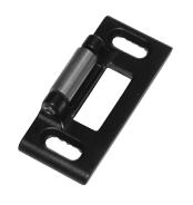
264 2 <sup>7</sup>/<sub>8</sub>" x 1 <sup>1</sup>/<sub>4</sub>" x <sup>9</sup>/<sub>16</sub>" (H x W x D) Panic device only.
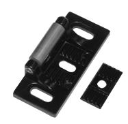
299 " x " x " (H x W x D) Panic device only.
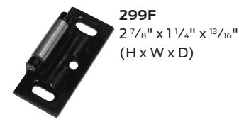
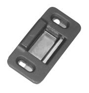
1606 2 <sup>7</sup>/<sub>8</sub>" x 1 <sup>3</sup>/<sub>8</sub>" x <sup>3</sup>/<sub>8</sub>" (H x W x D) Panic device only.
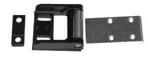
1439 Blade stop " x " x " (H x W x D) Panic device only.
For surface and concealed vertical rod devices
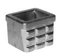
2130 (F)24-V and (F)24-C standard bottom strike for grouting into concrete or masonry floors.
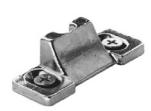
3788 Furnished top of (F)24-V.
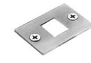
4155 Optional strike. Panic device only.
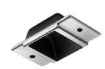
4188 Top strike for (F)24-C.
Accessories
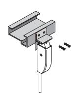
421
Angle bracket for flush transom applications. Does not require elimination of latch retention feature. Accepts 3788 strike for 24-V device.
Surface vertical extension rods
Extension rods are available in 12", 24" and 36" lengths in all finishes. Both ends tapped and all-thread included as connector.
Concealed extensionrods
Extension rods are available in 12", 24" and 36". Both ends have pressed-in, threaded inserts.
Filler plates
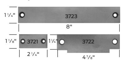
3721/3722/3723
Steel filler plates
3721 Cylindrical lock front filler
3722 Strike filler - set no. SC for 161 cutout
3723 Mortise lock front filler
3722 Strike filler - set no. SM for 86 cutout
24 Series Trim designs
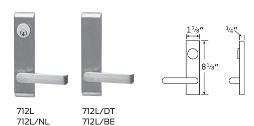
Lever trims (712L)
Knob trim (711K)
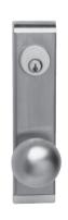
711K 711-NL
Round ball knob Escutcheon: 8 1 ⁄8" x 1 7 ⁄8" Projection: 3 7 ⁄8" Brass For keyed functions, see page 26 for cylinder requirements.
Athena (715)
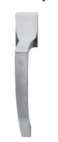
Grip overall: 9 1 ⁄8" Width: 1 11⁄16" Pull: 6 1 ⁄4" C x C Projection: 2 1 ⁄4 " 715DT
Lever designs
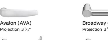
Quantum (QUA) Projection 3 1 ⁄4"
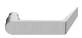
Dane (DAN) Projection 3"
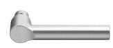
Broadway (BRW) ⁄5"
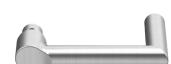
Boardwalk (BRK) Projection 3 1 ⁄5"
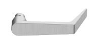
Danish (DSH) Projection 2 9 ⁄10"
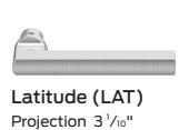
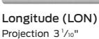
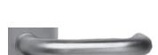
Sutro (SUT) Projection 3 1 ⁄4"
All levers return to within 1 ⁄2" of door.
Escutcheon: 8 1 ⁄8" (H) x 1 7 ⁄8" (W) (specify handing) brass finish.
Protected by easily replaceable shear pin.
Lever is reversible, supplied RHR if not specified. For keyed functions, see page 26 for cylinder requirements.
Delta trims
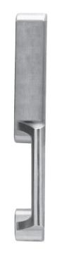
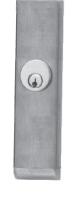
718DT 718C 718NL 717DT
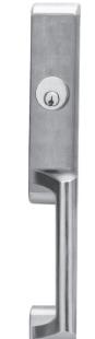
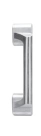
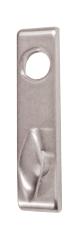
718TL 718TL-BE

Cylinder information
Key retracts latch bolt. Cylinder sold separately (see page 26).
Brass and/or plated finishes.
For cylinder information see page 26. When locking function is not required, specify trim by (BE) blank escutcheon.
Specify handing Escutcheon: 8 1 ⁄8" x 1 7 ⁄8" Projection: 2 1 ⁄4" All Delta pulls: 6 1 ⁄4" C x C NL and DT: 14 1 ⁄16" x 2 1 ⁄4"
24 Series
Trim chart & finish chart
Function
| Lock/ unlock | NL | DT | BE | NLOP | |
|---|---|---|---|---|---|
|
Lever1
(712) |
712L | 712L-NL | 712L-DT | 12L-BE | |
| Knob (711) | 711K | 711K-NL | — | 711K_BE | |
| Delta (717) | — | — | 717DT | — | |
| Delta (718) | — | 718NL | 718DT | — | 718C |
| Athena (715) | — | — | 715DT |
1 Specify hand.
24 Series finishes
| Color | US number | BHMA number |
|---|---|---|
| Brass, bright | US3 | 605 |
| Brass, satin | US4 | 606 |
| Bronze, satin | US10 | 612 |
| Bronze, aged | US11 | 643e* |
| Nickel, satin | US15 | 619* |
| Black, matte | US19 | 622* |
| Chromium, bright | US26 | 625 |
| Chromium, satin | US26D | 626 |
| Anodized aluminum | US28 | 628 |
| Stainless Steel, bright | US32 | 629 |
| Stainless Steel, satin | US32D | 630 |
| Anodized duranodic | 313AN | 710 |
* Available on select devices and trims
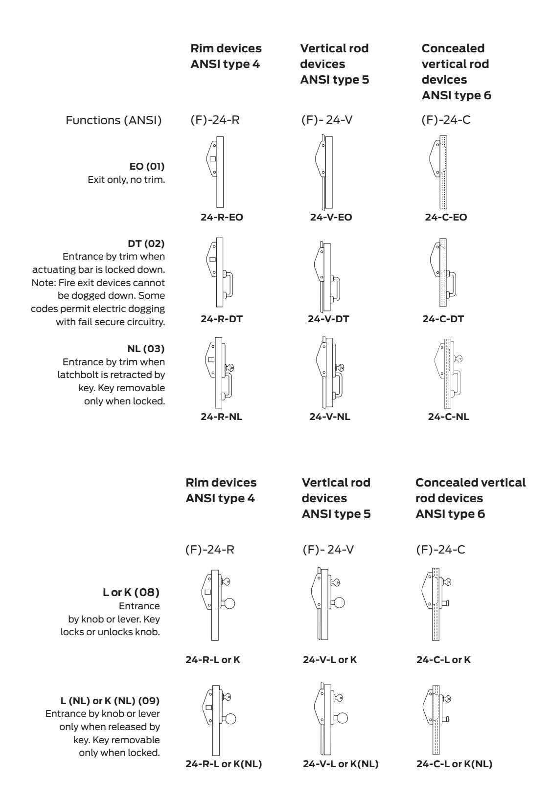
24 Series Types and functions
24 Series Door application
Label doors
Falcon models F-24-R, F-24-C and F-24-V are labeled for use as Zfire exit hardware.
Door thickness
All devices and components supplied for 1 3⁄4" – 3'0" x 7'0" doors standard. Specify door thickness if other than 1 3 ⁄4".
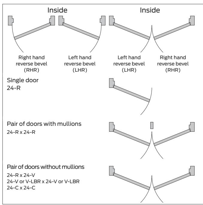
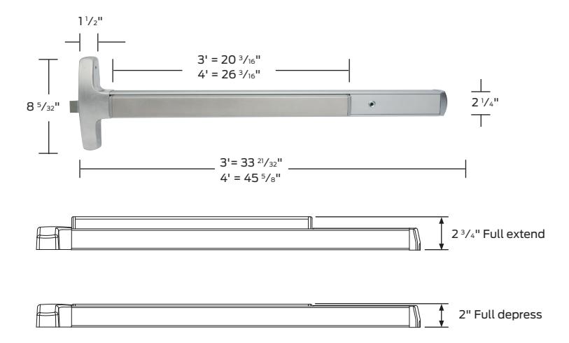
Door application chart
Product information and specifications contained in this catalog are subject to change without notice. Please consult the factory.
Motorized electric latch retraction
Motorized electric latch retraction (MEL) for 24 and 25 Series devices
Motorized electric latch retraction (MEL) provides energy efficient electronic control of an exit device for an affordable around the door solution. The MEL option is Falcon's solution of choice for multifamily and commercial real estate facilities where cost competitive electromechanical latch retraction is desired. It is available on most Falcon 24 and 25 Series exit devices (not available for mortise 25-M or F-25-M).
These devices always provide mechanical egress. Motorized electric latch retraction can be used with credential readers to unlatch doors momentarily for authorized users, or it can be incorporated with systems to retract latches for extended periods of time to allow free entry. This is a convenient alternative to mechanical dogging. Doors with automatic operators also may use exit devices with electric latch retraction.
The MEL option is available on panic and fire rated devices. Because fire exit hardware must be self latching, an automatic fire alarm system must be incorporated to drop power to fire rated MEL devices in case of fire.
Features and benefits
- § MEL option available on 24 and 25 Series exit devices, except 25-M (mortise)
- § Energy efficient motorized latch retraction enables longer wire runs and the use of a standard Schlage power supply with option board (see page 33)
- § Modular design allows for a simplified installation of the available MEL Conversion kit to existing mechanical Falcon 24 or 25 exit devices
- § On-board installation and troubleshooting diagnostics built into the motor assembly
- § Self-calibrating motor assembly
- § Pushbar is pulled in electronically when dogged
- § Vandal resistant detects and responds to events of attack and tampering
MEL system requirements
The MEL has a low inrush current = 1.0 amps, so it can be used with standard Schlage power supplies. When powering multiple components, verify that the amperage requirement of all components combined does not exceed the power supply output rating.
- § The MEL device is compatible with the following equipment: PS900 Series power supplies - PS902, 904, 906, 914; 900 Series Option Boards - 900-2RS, 900-4R and 900-4RL
- § A power transfer (EPT, electrified hinge, or door loop) is required and sold separately
Compatible options
- § Security monitoring (DM, LM, RX)
- § Fail Safe/Fail Secure electric trim (FSA/FSE)
How to order:
- § To order the MEL feature add "MEL" prefix to device designation (example: MEL-25-R-EO)1
- § To order the MEL feature with Allegion Connect, add "MEL" prefix and "CON" suffix to device designation
- § To order the MEL conversion kit, please specify finish with part number (US3, US4, US10, US26, US26D, US32D, SP28, SP313)2
- 1. Mechanical dogging is not an option with MEL.
- 2. MEL kits may not be used to convert an EL device. MEL conversion kits are only compatible with mechanical Falcon 24 and 25 series exit devices.
| Model no. | Description | Part number |
Part number with
Allegion Connect (-CON) |
|---|---|---|---|
| 25-MELK-3 | 25 Motorized electric latch retraction kit 3' | 47266630 | 47266630 |
| 25-MELK-4 | 25 Motorized electric latch retraction kit 4' | 47266631 | 47266631 |
| 24-MELK-3 | 24 Motorized electric latch retraction kit 3' | 47266632 | 47266632 |
| 24-MELK-4 | 24 Motorized electric latch retraction kit 4' | 47266633 | 47266633 |
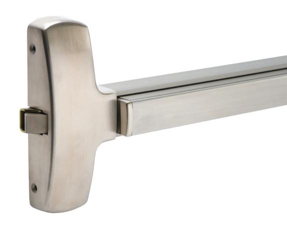
Motorized electric latch retraction
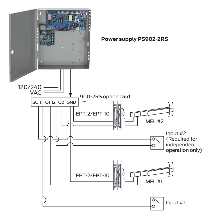
Application and wiring
Popular application and wiring - motorized electric latch retraction (MEL)
| Device |
Door
size |
Door
strike |
Minimum door opening width
(Add 3.5" to standard) |
|---|---|---|---|
| MEL-24-R | 3' | 299 | 2' 11" |
| 264 |
2' 10 7
⁄8" |
||
| 1439 |
2' 10 1
⁄4" |
||
| 1606 | 2' 10 5⁄8" | ||
| MEL-24-R | 4' | 299 | 3' 5" |
| 264 |
3' 4 7
⁄8" |
||
| 1439 |
3' 4 1
⁄4" |
||
| 1606 | 3' 4 5⁄8" | ||
| MEL-24-C | 3' | All | 2' 10 5⁄8" |
| MEL-24-C | 4' | All | 3' 4 5⁄8" |
| MEL-24-V | 3' | All | 2' 10 5⁄8" |
| MEL-24-V | 4' | All | 3' 4 5⁄8" |
| MEL-25-R | 3' | 299 | 2' 11" |
| 264 |
2' 10 7
⁄8" |
||
| 1439 |
2' 10 1
⁄4" |
||
| 1606 | 2' 10 5⁄8" | ||
| MEL-25-R | 4' | 299 | 3' 5" |
| 264 |
3' 4 7
⁄8" |
||
| 1439 |
3' 4 1
⁄4" |
||
| 1606 | 3' 4 5⁄8" | ||
| MEL-25-C | 3' | All | 2' 10 5⁄8" |
| MEL-25-C | 4' | All | 3' 4 5⁄8" |
| MEL-25-V | 3' | All | 2' 10 5⁄8" |
| MEL-25-V | 4' | All | 3' 4 5⁄8" |
Popular application shown above. See page 39 for other power supply details.
Power transfer - motorized electric latch retraction (MEL)
A power transfer (EPT, electrified hinge, door loop) provides a wiring path from the door to the frame. If an EPT (Electric Power Transfer) is utilized, the door and frame must be factory prepped.
EPT options
- § EPT-2: Two 18AWG wires with a max rating of 24VDC, 5A or 120 VAC NEC class 3
- § EPT-10: Ten 24AWG wires with a max rating of 24VDC, 1A
| EPT can be used for: | EPT cannot be used for: |
|---|---|
| Door thickness - 1 3⁄4" minimum |
1 1
⁄2" offset pivots |
| 0-180 degree opening with up to 5" butt hinges1 | Larger than 6" butt hinges |
|
0-130 degree opening with up to 5 1
⁄2" butt hinges1 |
Pocket pivots |
| 0-110 degree opening with up to 6" butt hinges1 | Swing clear hinges |
| 0-180 degree opening with up to 3⁄4" offset pivots1 | Center hung doors (center pivot) |
| Balanced door | |
1. Specifications only apply to a 1 3 ⁄4" thick door.
Delayed egress system components
For all 24 and 25 Series
The delayed egress system provides control for limited egress and high security areas which require accident hazard or fire exit hardware.
Delayed egress function
When the delayed egress system is armed, the mag lock(s) will remain secure against attempted override pressure and severe impacts. Ingress requires an operational trim, along with access control input (i.e. card reader, key switch, keypad). The system is required to be tied into local fire alarm system.
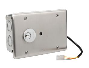
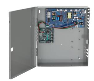
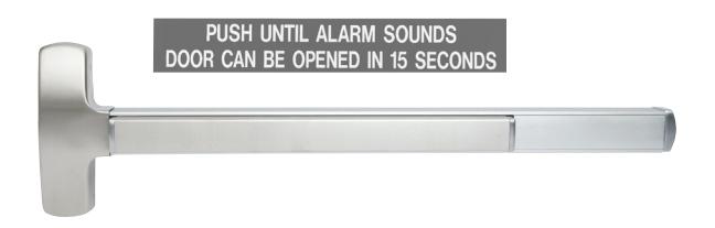
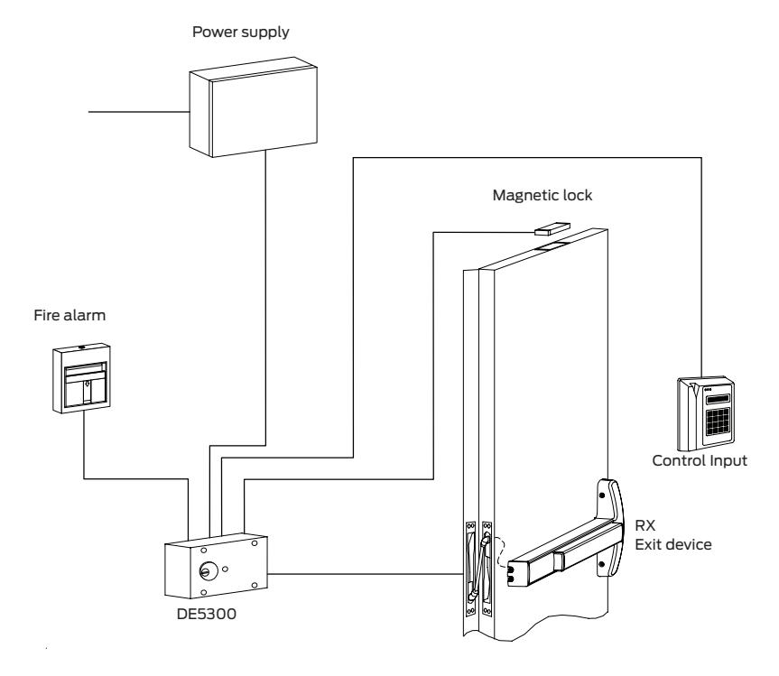
A complete delayed egress system requires the following components:
- § DE5300 is used in delayed exit application and is ideal for controlled areas.
- § Key switch operator
- § Arm, disarm, reset and bypass the delayed egress system by the mortise cylinder on the dialogue box. (1- 1 ⁄4" mortise cylinder sold separately.)
- § LED status indicator
- § Red LED indicates arm. Disarm and alarm status.
- § Alarm horn
- § Depression of the Falcon 24 or 25 RX device touchpad initiates a local alarm of 100 dB when armed.
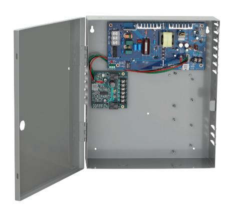
Falcon 25 Series device with RX switch PS902 Power supply
§ PS902 - The series PS902 power supply is the recommended power supply for use with the delayed egress system. The series PS902 power supply is designed for electric locking or monitoring on single or double door applications. The output power is field selectable for either 24 VDC@1 ampere or 12 VDC@2 ampere. Standard input 120 VAC@0.6 ampere and 240 VAC@3.0 ampere available. The terminal block will accept up to 14 gauge stranded wire.
Power supply
§ PS900 Series - A PS900 Series power supply can be safely used with the delayed egress system (see page 39 for more information).
Magnetic locks - Schlage electronics M420, M450 or M490 maintains UL listing.
How to order:
All components above are sold separately. To order, specify each component to complete a delayed egress system for your application.
Application and wiring Popular delayed egress diagram
Minimum door opening sizes
(Jamb to jamb, or for double door- jamb to center of opening)
| Device | Door size | Door | DE5300 for |
|---|---|---|---|
| strike | standard devices | ||
| 24-R | 3' | 299 | 2'71/2" |
| 264 | 2' 7 3/8" | ||
| 1439 | 2' 6 3/4" | ||
| 1606 | 2'71/8" | ||
| 24-R | 4' | 299 | 3'11/2" |
| 264 | 3'13/8" | ||
| 1439 | 3'11/8" | ||
| 1606 | 3'11/8" | ||
| 24-C | 3' | All | 2' 7 1/8" |
| 24-C | 4' | All | 3'11/8" |
| 25-R | 3' | 299 | 2'73/4" |
| 264 | 2' 7 3/8" | ||
| 1439 | 2' 6 3/4" | ||
| 1606 | 2'71/8" | ||
| 25-R | 4' | 299 | 3'11/2" |
| 264 | 3'13/8" | ||
| 1439 | 3'11/8" | ||
| 1606 | 3'11/8" | ||
| 25-C | 3' | All | 2' 7 3/8" |
| 25-C | 4' | All | 3'13/8" |
| 25-M | 3' | All | 2' 7 1/2" |
| 25-M | 4' | All | 3' 2" |
Electric lock or unlock trim
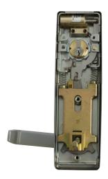
Electric lock or unlock trim (FSA/FSE) for 25 Series
The electric lock or unlock (FSA/FSE) feature allows the controlling of trim while still maintaining free egress at all times. The lock or unlock command can be controlled by a security system, fire alarm system, key switch, card reader, push button or touchpad.
FSA (Fail safe–unlocks when power is interrupted) can be used in areas requiring doors to be unlocked due to fire, power failure or emergency situations. (Examples: stairwells, hospitals, fire exits, etc.)
FSE (Fail secure–locks when power is interrupted) can be used in areas requiring doors to be locked for security reasons and only unlocked when energized by authorized personnel. (examples: banks, inner-office, etc.) With either feature, authorized personnel can gain access utilizing key by overriding or bypassing electric locking function.
Wire chart
| Length of wire run (ft.) |
24VDC
0.4 AMPS |
|---|---|
| 0-500 | 18AWG |
| 501-700 | 16AWG |
Specifications
- § Solenoid rated for continuous duty at 24V DC 0.4 amps.
- § UL listed devices.
- § Device channel is used as conduit on 25 Series devices.
- § Power transfer (EPT-2) hinge 2-wire minimum rated 1 ⁄2 Amp.
- § See page 35 for more information
How to order
To order FSA/FSE feature, add FSA or FSE prefix to device designation. (Example: FSA 25-R-L)
Note:
- 1. FSA/FSE can be used on all devices.
- 2. The FSA/FSE feature can be used in conjunction with MEL (Motorized electric latch retraction), EA (exit alarm) and security monitoring (DM, LM, RX).
Minimum power supply- PS902
- § The series 902 power supply is the recommended power supply for use with an FSA or FSE trim. The series 902 power supply is also designed for electric locking or monitoring of single or double door applications.
- § See page 32 for more information
Exit alarm
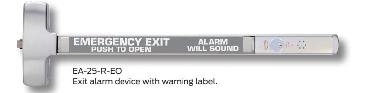
Exit alarm (EA) - for all 24 and 25 Series devices
The Exit alarm (EA) feature provides a battery powered exit alarm to allow for a simple and effective means of monitoring the use of exits while still maintaining means of egress (for code requirements). When the touchbar is depressed the alarm will sound continuously, indicating that the exit has been engaged. The exit alarm can only be reset by way of a standard 1 1 ⁄4" mortise cylinder with standard "A" cam (5⁄16" wide x 3⁄4" long). The design of the unit will allow the single 9V battery to last for at least six months (on standby mode).
Minimum door width required for standard devices
| Device | Door size |
Door
strike |
Min door
opening width |
|---|---|---|---|
| EA-24-R | 3' | 299 |
2' 9 1
⁄4" |
| 264 |
2' 9 1
⁄8" |
||
| 1439 | 2' 8 3⁄8" | ||
| 1606 |
2' 8 7
⁄8" |
||
| EA-24-R | 4' | 299 |
3' 3 1
⁄4" |
| 264 |
3' 3 1
⁄8" |
||
| 1439 |
3' 3 7
⁄8" |
||
| 1606 |
3' 3 7
⁄8" |
||
| EA-24-C | 3' | All |
2' 9 1
⁄8" |
| EA-24-C | 4' | All |
3' 3 1
⁄8" |
| EA-24-V | 3' | All |
2' 8 7
⁄8" |
| EA-24-V | 4' | All |
3' 2 7
⁄8" |
| EA-25-R | 3' | 299 |
2' 9 1
⁄4" |
| 264 |
2' 9 1
⁄8" |
||
| 1439 | 2' 8 3⁄8" | ||
| 1606 |
2' 8 7
⁄8" |
||
| EA-25-R | 4' | 299 |
3' 3 1
⁄4" |
| 264 |
3' 3 1
⁄8" |
||
| 1439 |
3' 3 7
⁄8" |
||
| 1606 |
3' 3 7
⁄8" |
||
| EA-25-C | 3' | All |
2' 8 7
⁄8" |
| EA-25-C | 4' | All |
3' 2 7
⁄8" |
| EA-25-M | 3' | All |
2' 9 1
⁄4" |
| EA-25-M | 4' | All |
3' 3 1
⁄4" |
| EA-25-V | 3' | All |
2' 8 7
⁄8" |
| EA-25-V | 4' | All |
3' 2 7
⁄8" |
Specifications
- § Works with rim, mortise, concealed, surface vertical rod
- § UL listed
- § The EA feature can be used in conjunction with FSA/FSE (Fail safe/Fail secure trim) and security monitoring (DM, LM, RX) features.
Features and benefits
- § 110 dB alarm
- § 24 Volt hardwire option
- § 9V Battery input
- § External inhibit for card reader
-
§ LED indication
- − Armed
- − Disarmed
- − Low battery
- − EAK retrofit kit avialable for your existing devices
How to order
To order EA feature add "EA" prefix to device designation. (example: EA-25-R-EO)
To order EAK (exit alarm kit) feature order "EAK" plus device length (3' or 4'), type of device (24 or 25 Series) and the finish of your existing device. (example: EAK-4', 24 Series, US10) (For retrofit application)
Minimum power supply - PS902
The series PS902 power supply is the recommended power supply for use with the exit alarm (EA) option. The series PS902 power supply is designed for electric locking or monitoring on single or double door applications (see page 32 for more information).
Device monitoring
Device monitoring for most 24 and all 25 Series devices*
All of the monitoring features available from Falcon provide total flexibility and will interface with any security system. All monitoring switches are dry contact type and are contained within the device, allowing for tamper-resistant operation. Security monitoring features allow monitoring of devices, latches, authorized egress and locking levers. A key override option is available. All of the security monitoring features can be used in any combination with any other Falcon feature. Consult factory for special applications.
*DM, *LM, RX Monitoring
- § The DM (device monitor) feature monitors full latch projection. If the latchbolt is retracted by use of device, or someone tampers with the latchbolt, the switch is activated sending a signal to controlling areas. In devices with the deadlock feature, the deadlatch status is monitored.
- § The LM (Latch monitor) feature monitors full latchbolt retraction. When the latchbolt is fully retracted a signal is sent indicating door (or device) opened status.
- § The RX feature monitors the depression of the touch bar or crossbar. Activation of the switch indicates use of a door or that the door is in the dogged condition. This feature is especially useful when used to activate or shunt magnetic locking systems.
- § *LM/DM not available on F-24-R.
How to order
To order any individual or combination of monitor feature(s) add the respective prefix(s) to device designation. (example: EL-RX-DM-25-V-L-DANE)
Key override option (KOR)
The KOR feature allows authorized personnel to override monitoring features on a door by use of a keyed 1 1 ⁄8" mortise cylinder with 5⁄16" wide x 3⁄4" long standard cam (mortise cylinder not supplied).
Activating KOR feature allows any feature to be disabled for daytime use or when desired by key holder. This is a maintained contact switch. KOR is especially useful for turning on or off magnetic locking systems and electric dogging control (at the door).
This feature is not available with EA feature, cylinder/standard dogging. To order KOR feature add KOR prefix to device designation. (example: KOR-DM-24-R-TP)
Note: Use of these features may require a power transfer hinge (supplied by others) or additional wires in the power transfer hinge needed for application when combined with other electrified features.
Power supply
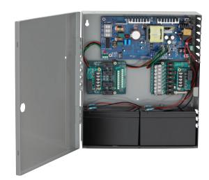
The PS900 Series is a consolidated line of power supplies and accessories that offer enhanced flexibility and functionality specific to the changing needs of the access control market. The PS900 Series can be used in a variety of applications to convert high voltage AC power into the low voltage DC outputs required by most access control devices. The PS900 Series protects devices downstream by providing Class 2* , filtered and regulated power. The full line is UL294 certified.
Note: PS906 can provide Class 2 rated outputs when used with 900-8P distribution board.
Features:
- § Constant output rating at both 12 VDC and 24 VDC provides superior performance; includes field selectable jumper
- § Polarized connectors for option boards eliminate need for racks and side connectors
- § Flat mounting of option boards provides easier access to terminal blocks for connection of electrified devices
- § High voltage protective cover
- § Battery back-up board auto-selects voltage
- § Fire alarm relay can be configured to provide either switched or un-switched outputs from a power supply
- § PS914 designed with high in rush current for powering solenoid-driven electrified panic devices
- § Universal 120-240 VAC input
- § Low voltage DC, regulated and filtered
- § Electronic power limiting foldback circuit for AC current overload protection
- § Fused primary input
- § AC status monitor- isolated SPDT contacts
- § AC input and DC output LED status indicators
- § Cover mounted AC input indication
- § Hinged cover with lock down screws
Certifications:
- § UL 294 certified—the standard for access control
- § Class 2 rated* * Except PS906, output rating exceeds Class 2 power limits
Once power is converted to low voltage DC, the PS900
Series offers a variety of distribution options, including basic fuse protection, simple relay, and advanced logic providing complex sequencing and timing functions.
* PS906 can provide Class 2 rated outputs when used with 900-8P distribution board.
| PS902 | PS904 | PS906 | PS914 | |
|---|---|---|---|---|
|
Number of connectors on
power supply for the following: |
2 amps | 4 amps | 6 amps | 4 amps |
| Distribution boards | 1 | 2 | 3 | 2 |
| Battery back-up board | 1 | 1 | 1 | 1 |
Note: One fire alarm board can be connected directly to the PS902. If a fire alarm board is desired for the PS904, PS906 or PS914 it can be connected to a distribution board.
Applications:
The PS900 Series of power supplies works with many electrified devices including Falcon exit devices, electromagnetic locks, hardwired locks, electrified mechanical locks, electrified strikes and many other products.
Accessories:
The PS900 Series features seven option boards for use in a variety of applications. All PS900 Series power supplies option boards are UL 294 certified.
Option boards:
900-4R: 4 relay controlled output board to power multiple devices.
900-4RL: 4 relay distribution board with logic is field configurable for time delay function, auto operator, security interlock.
900-8F: Provides 8 individually fuse-protected outputs, giving the flexibility to power multiple devices and provide another layer of protection.
900-FA: Emergency interface relay integrates with fire alarm and is used to cut power in case of emergency.
900-BB: Battery backup.
900-2RS: 2 relay MEL or EL panic device control board. 900-BBK: Battery backup kit includes two 7A/hr batteries and provides up to four hours of backup power when cycled every 5 minutes at full load.
Wire selection size/type
| Run length (one way) | MEL device w/EPT, electric hinge, door loop |
|---|---|
| 200' | 18 AWG |
| 320' | 16 AWG |
| 500' | 14 AWG |
| 800' | 12 AWG |
Electrical options summary
Electrical options matrix - 25 Series
| Option |
Electric
dogging |
Motorized
electric latch retraction (MEL) |
Delayed
egress |
Electric lock
/unlock trim (FSA/FSE) |
Device
monitor (DM) |
Latch
monitor (LM) |
Authorized
egress (RX) |
Key
override (KOR) |
Exit alarm
(EA) |
|---|---|---|---|---|---|---|---|---|---|
|
Motorized electric latch
retraction (MEL) |
X | — | V | V | V | V | V | X | X |
| Delayed egress | V | V | — | V | V | V | V | V | V |
|
Electric lock/unlock trim
(FSA/FSE) |
V | V | V | — | V | V | V | V | V |
| Device monitor (DM) | V | V | V | V | — | V | V | V | V |
| Latch monitor (LM) | V | V | V | V | V | — | V | V | V |
| Request to exit (RX) | V | V | V | V | V | V | — | V | V |
| Key override (KOR) | X | X | V | V | V | V | V | — | X |
| Exit alarm (EA) | X | X | V | V | V | V | V | X | — |
Electrical options matrix - 24 Series
| Option |
Electric
dogging |
Motorized
electric latch retraction (MEL) |
Delayed
egress |
Device
monitor (DM) |
Latch
monitor (LM) |
Authorized
egress (RX) |
Key
override (KOR) |
Exit alarm
(EA) |
|---|---|---|---|---|---|---|---|---|
|
Motorized electric latch
retraction (MEL) |
X | — | V | V | V | V | X | X |
| Delayed egress | V | V | — | V | V | V | V | V |
| Device monitor (DM)* | V | V | V | — | V | V | V | V |
| Latch monitor (LM)* | V | V | V | V | — | V | V | V |
| Request to exit (RX) | V | V | V | V | V | — | V | V |
| Key override (KOR) | X | X | V | V | V | V | — | X |
| Exit alarm (EA) | X | X | V | V | V | V | X | — |
* Not available on 24-R/F-24-R.
V = works with
X = doesn't work
How to order
25 Series
| MEL | F | 25 | V | L-DANE | US3 | 3' | LHR | LBR | SNB WD | |||||
|---|---|---|---|---|---|---|---|---|---|---|---|---|---|---|
| Prefixes | ||||||||||||||
| CD | Cylinder dogging | |||||||||||||
| RX | Touchbar request to exit | |||||||||||||
| DM | Latchbolt and device monitor switch | |||||||||||||
| EA | Exit alarm | |||||||||||||
| KOR | Key bypass switch | |||||||||||||
| LD | Less dogging | |||||||||||||
| LM | Latchbolt status switch | |||||||||||||
| MEL | Motorized electric latch retraction | |||||||||||||
| FSA | Electric lock or unlock trim-fail safe | |||||||||||||
| FSE | Electric lock or unlock trim-fail secure | |||||||||||||
| Rating | ||||||||||||||
| F | Fire exit hardware | |||||||||||||
| Blank | Panic exit hardware | |||||||||||||
| Device series | ||||||||||||||
| 25 | Touch bar device, wide stile | |||||||||||||
| Device type | ||||||||||||||
| R | Rim | C-WDC Concealed vertical rod | ||||||||||||
| V | Surface vertical rod | wood door (20 or 90 min) | ||||||||||||
| C | Concealed vertical rod | M | Mortise | |||||||||||
| Trim function (see trim pages for all functions) | ||||||||||||||
| EO | Exit only | K | Knob | |||||||||||
| DT | Dummy trim | L | Lever (Dane standard) | |||||||||||
| NL | Night latch | C | Cylinder prim plate | |||||||||||
| NL-OP | Night latch optional pull | 511-L | VR trim | |||||||||||
| TP | Thumbpiece | |||||||||||||
| Finish | ||||||||||||||
| US3 | US10 | US11 | US15 | US19 | US26 | |||||||||
| US32 | US28 | US4 | US26D | US32D | 313AN | |||||||||
| Door width | Door thickness | |||||||||||||
| 3' | Standard default | 1 3⁄4" Standard | ||||||||||||
| 4' |
2 1
⁄4" Optional |
|||||||||||||
| Handing | ||||||||||||||
| RHR | Right hand reverse | |||||||||||||
| LHR | Left hand reverse | |||||||||||||
|
Less bottom rod
LBR |
Less bottom rod | |||||||||||||
| Accessories | ||||||||||||||
| CYL | Cylinder | SNB | Sex bolts | |||||||||||
| SK | Shim kit | AMS | All machine screws (for vertical and concealed only) | |||||||||||
| Other miscellaneous door information | ||||||||||||||
| HMD | Hollow metal door | — | Door thickness | |||||||||||
| HMF | Hollow metal frame | — | Door undercut | |||||||||||
| WD | Wood door | — | Door label | |||||||||||
| WDF | Wood frame | — | Stile width | |||||||||||
| ALD | Aluminum door | — | Frame stop height | |||||||||||
| ALF | Aluminum frame | SGL | Single door | |||||||||||
| Steel channel door construction | PR | Pair of doors swinging same direction | ||||||||||||
| SCDC | ||||||||||||||
| — | Specify other door or frame | |||||||||||||
| — |
Material information
Door height |
How to order
24 Series
| MEL | V | L-DANE | US3 | 3' | LHR | LBR | SNB WD | ||||||
|---|---|---|---|---|---|---|---|---|---|---|---|---|---|
| Prefixes | |||||||||||||
| CD | Cylinder dogging | ||||||||||||
| RX | Touchbar request to exit | ||||||||||||
| DL | Deadlocking | ||||||||||||
| DM | Latchbolt and device monitor switch | ||||||||||||
| EA | Exit alarm | ||||||||||||
| KOR | Key bypass switch | ||||||||||||
| LD | Less dogging | ||||||||||||
| LM | Latchbolt status switch | ||||||||||||
| MEL | Motorized electric latch retraction | ||||||||||||
| Rating | |||||||||||||
| F | Fire exit hardware | ||||||||||||
| Blank | Panic exit hardware | ||||||||||||
|
Device series
24 |
Touch bar device, narrow stile | ||||||||||||
|
Device type
R |
Rim | C | Concealed vertical rod | ||||||||||
| V | Surface vertical rod | C-WDC | Concealed vertical rod | ||||||||||
| wood door | |||||||||||||
| Trim function (see trim pages for all functions) | |||||||||||||
| EO | Exit only | K | Knob | ||||||||||
| DT | Dummy trim | L | Lever (Dane standard) | ||||||||||
| NL | Night latch | ||||||||||||
| C | Cylinder trim less pull | ||||||||||||
| Finish | |||||||||||||
| US3 | US10 | US26 | US32 | 313AN | |||||||||
| US4 | US26D | US32D | US28 | ||||||||||
| Door thickness | |||||||||||||
| Standard default |
1 3⁄4" Standard
2 1 ⁄4" Optional |
||||||||||||
|
Right hand reverse
Left hand reverse |
|||||||||||||
| Less bottom rod | |||||||||||||
|
Door width
3' 4' Handing RHR LHR Less bottom rod LBR Accessories |
|||||||||||||
| Cylinder | SNB | Sex bolts | |||||||||||
| Shim kit | AMS | All machine screws (for vertical and concealed only) | |||||||||||
| Other miscellaneous door information | |||||||||||||
| Hollow metal door | — | Door thickness | |||||||||||
| Hollow metal frame | — | Door undercut | |||||||||||
| Wood door | — | Door label | |||||||||||
| Wood frame | — | Stile width | |||||||||||
| Aluminum door | — | Frame stop height | |||||||||||
| Aluminum frame | SGL | Single door | |||||||||||
| Steel channel door construction | PR | Pair of doors swinging same Direction | |||||||||||
|
CYL
SK HMD HMF WD WDF ALD ALF SCDC — |
Specify other door or frame | ||||||||||||
| material information |
* Not available for F-24-R
How to order
Trim
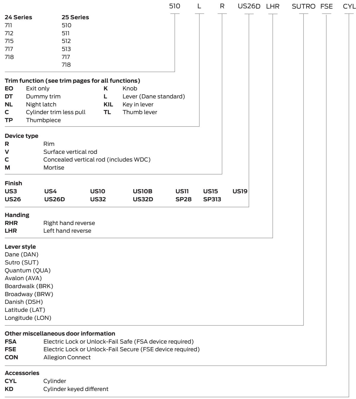
Door thickness
Specify door thickness other than 1 3⁄4"
About Allegion
Allegion (NYSE: ALLE) is a global pioneer in safety and security, with leading brands like CISA®, Interflex®, LCN®, Schlage®, SimonsVoss® and Von Duprin®. Focusing on security around the door and adjacent areas, Allegion produces a range of solutions for homes, businesses, schools and other institutions. Allegion is a $2 billion company, with products sold in almost 130 countries.
For more, visit www.allegion.com