FM8700, 12-FM8700 Surface Vertical Rod Exit Device Installation Instructions
Open the original PDF document
View PDFInstallation Instructions

FM8700, 12-FM8700
Surface Vertical Rod Exit Device
1-800-727-5477 • www.sargentlock.com
⚠ WARNING
This product can expose you to lead which is known to the state of California to cause cancer and birth defects or other reproductive harm. For more information go to www.P65warnings.ca.gov.
A7827E 6/22
Experience a safer and more open world
Surface Vertical Rod Exit Device
Installation Instructions Manual

Note: This device is one component of a specific combination of hardware required for this opening to meet FEMA 361 requirements. Follow all installation stepsas directed, in sequence given.
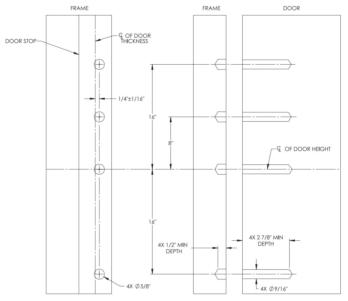
Note: For all 12-FM8700 single door application, (4) thermal pins are required. See Template 4628 in Step 14.
Note: For rail lengths and cutting instructions, see Step10.
Surface Vertical Rod Exit Device
Installation Instructions Manual

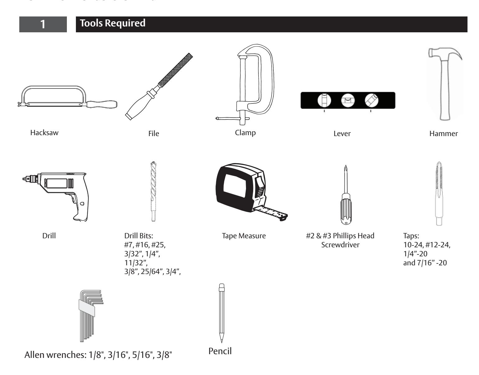
1 Tools Required, continued
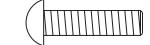
FASTENER CHART
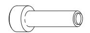
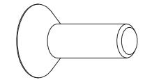

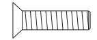
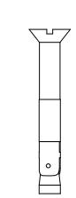
1/4-20 CONCRETE SLEEVE ANCHORS
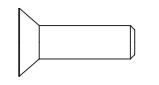
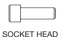
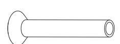

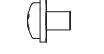
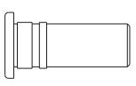
3
Surface Vertical Rod Exit Device
Installation Instructions Manual

2 Door Preparation
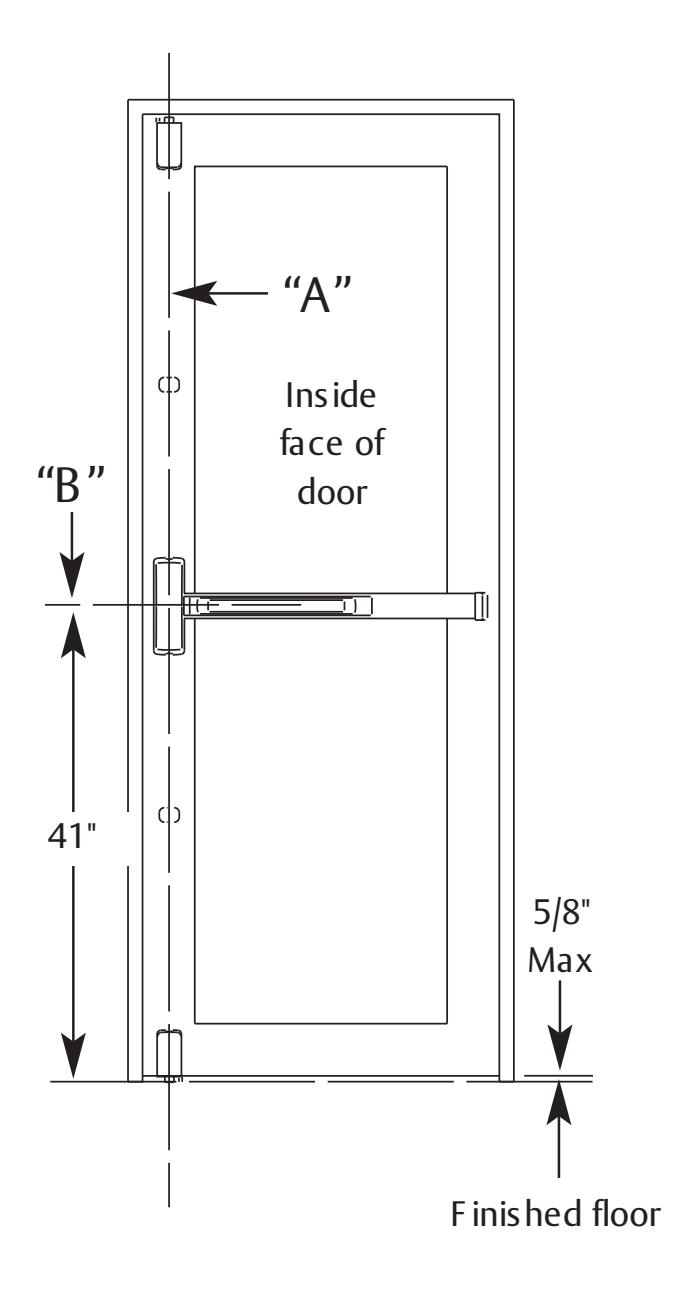
- 1. Mark vertical reference line A. A is the centerline for the chassis, top and bottom cases.
- 2. Mark horizontal reference line B at 41" above the finished floor. B is centerline for the chassis and rail.
- 3. Tape top case and chassis templates to the door (packed with the device).
Surface Vertical Rod Exit Device
Installation Instructions Manual
3 Install Top Bolt and Strike
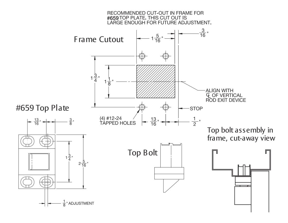
- 1. Prepare cut-out in frame for 659 Top Bolt / Strike. Use 11/64" drill, 12-24 tap, #3 Phillips screwdriver.
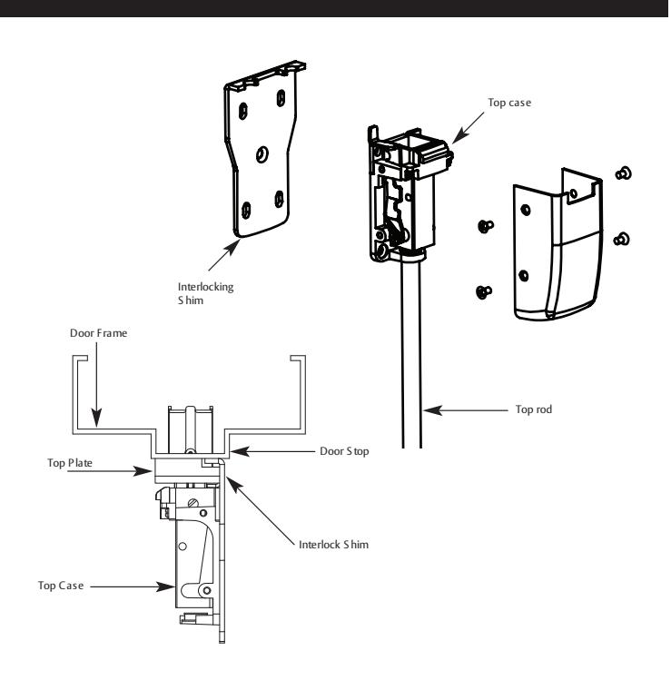
- 2. Install 659 Top Bolt/Strike. Transfer vertical centerline to door frame. With the door closed, align the interlocking shim with the 659 Top Bolt / Strike and place on vertical reference line. Mark and drill four mounting holes using 11/64" drill and 12-24 tap.
- 3. Mount 659 Top Bolt/Strike, (4) #12-24 x 3/4" Phillips Head Flat H.D. machine Screws.
Note: All four fasteners required. Do not tighten until Step 5.
Surface Vertical Rod Exit Device
Installation Instructions Manual

4 Install Top Case
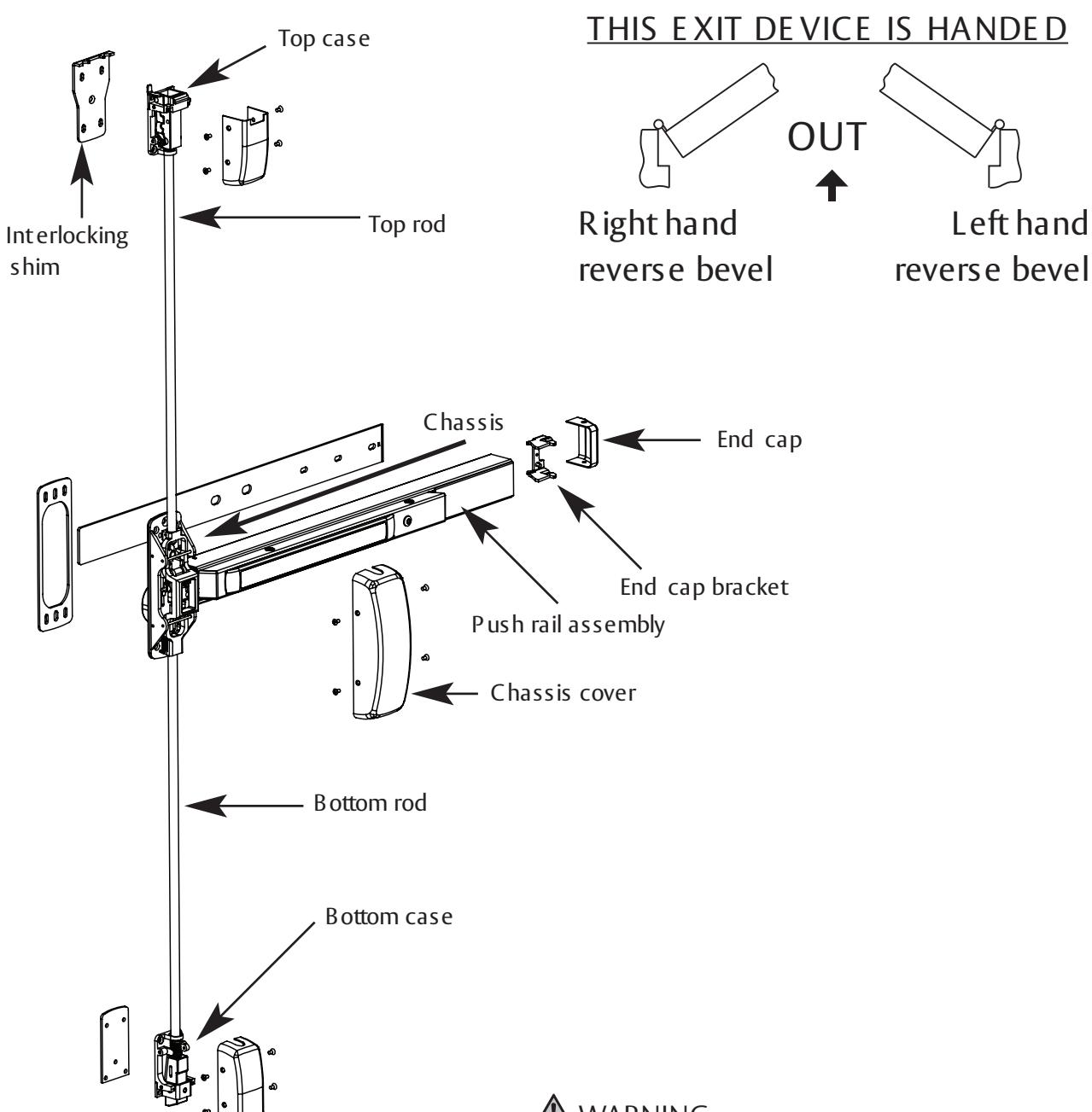
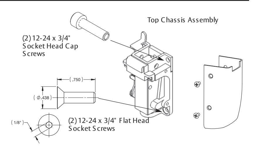
- 1. With the door closed, center the Top Chassis Assembly and Interlocking Shim on the vertical reference line. The Interlocking Shim must be engaged in the Top Bolt/Strike.
- 2. Mark location of (4) mounting screws.
- 3. Use 3/8" Drill Bit to drill two Top Mounting Holes through the door. Install (2) sex nuts, p/n #60-0502 from the outside door surface. Install (2) 12-24 x 3/4 Socket Head Cap Screws from Inside.
- 4. Attach using (2) 12-24 x 3/4" Flat Head Socket Head Screws in two bottom holes (1/8" Allen Wrench).
5 Securing Interlocking Shim
- 1. With the Top Chassis Assembly and Interlocking Shim secured, the 659 Top Bolt / Strike should engage the Top Chassis Assembly and Interlocking Shim when the door is closed.
- 2. Trace the outline of the Interlocking Shim.
- 3. Remove the Top Chassis Assembly to expose the center hole on the Interlocking Shim. Ensure the Interlocking Shim is aligned with the tracing. Mark and tap center hole (1) 12-24 x 3/4" Flat Head Socket Head Screw.
- 4. Reinstall Top Chassis Assembly.
- 5. Check for Top Chassis Assembly and 659 Top Bolt / Strike engagement. Tighten all screws.
- 6. Install Top Case Cover using (4) 8-32 x 5/16" screws.
1-800-727-5477 • www.sargentlock.com A7827E 6/22
Surface Vertical Rod Exit Device
Installation Instructions Manual

6 Install Center Chassis
1. Secure Chassis and Chassis Shim with (4) #10-24 x 3/4" Phillips Head Flat H.D. Machine Screws, 4 corner mounting holes.
Note: Use all four screws provided.
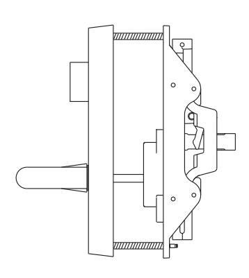
P OS ITION TRIM ON DOOR - Align spindle with B E L L HOUS ING
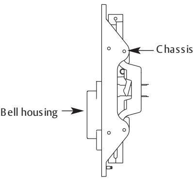
THRU-B OLT C HAS S IS to E T TRIM with (2) 1/4" -20 x 2 3/8" P H.F L .HD.Mach. S crews
7 Rail Shim Lengths and cutting Instructions
1. Refer to rail size listed on the box the device was shipped in. Break Rail Shim to the length that corresponds to the rail size.
Note: If shim needs to be cut, always cut shim from the end closest to the hinge edge.
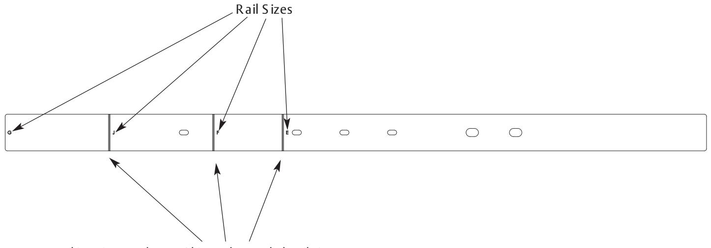
Use Breaking L ines to shorten S him to the needed R ail size
7
Surface Vertical Rod Exit Device
Installation Instructions Manual

8 Install Rail
Note: Do not install through-bolts until installation is complete and all mounting screws are tight. Do not install chassis cover at this time.
- 1. Level rail assembly on door. Use rail assembly as template. Mark and punch locations for threaded holes.
- 2. Remove rail assembly from door.
- 3. Drill and tap (2) holes as shown in door surface (#7 drill, 1/4-20 tap, 25/64" drill, 7/16-20 tap).
- 4. With rail shim under the mount install push rail assembly on to door.
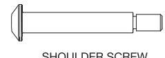
- 5. Install shoulder and socket head screw (3/16" wrench for 1/4"-20 bolt, 3/8" wrench for 7/16" screw).
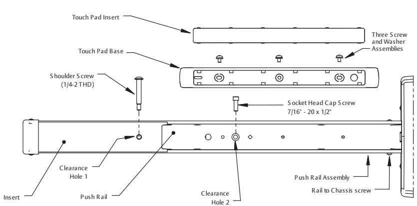
- 1. Attach touch pad base to push rail with (3) screw and washer assemblies.
- 2. Snap touch pad insert into touch pad base.
- 3. Install End Cap Bracket. Attach to door using (2) #10-24 x 3/4" Phillips round head machine screws.
- 4. Tighten all screws. Install hinge side cover using (2) #8-32 x 5/16" Phillips oval head machine screws.
9 Install Bottom Strike
Surface Mount 653 Bottom Strike
- 1. Transfer vertical centerline to threshold.
- 2. Drill holes 1 5/8" to 1 3/4" deep for (3) 1/4" sleeve anchors.
- 3. Disassemble anchors and drop lower portion into hole with threads towards top of hole.
- 4. Align holes in strike with holes in floor.
- 5. Screw top half of anchor onto the installed piece through the holes in the strike. Tighten anchors securely.
653 Strike 653 Strike
653 Bottom Strike Panic & Fire Rated
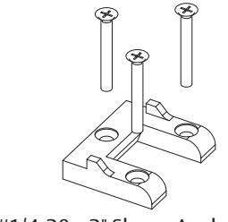
(3) #1/4-20 x 2" Sleeve Anchors
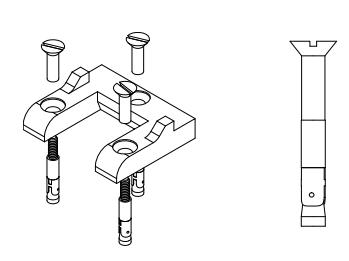
(3) 01-9679 Sleeve Anchors
Note: No Clearance in floor is required.
Surface Vertical Rod Exit Device
Installation Instructions Manual
SARGENT ASSA ABLOY
10
Install Bottom Case
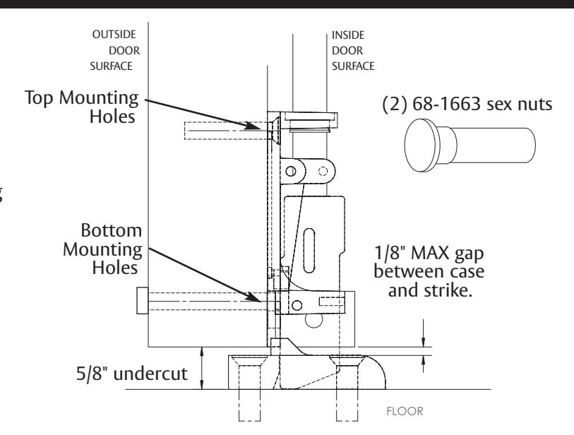
- 1. Using the vertical reference line, with bottom case as a template, Align Bottom Case for 1/8" maximum gap between case and strike.
- 2. Drill and tap top mounting holes for (2) 12-24 x 3/4" flat head socket screws, using 11/64" drill and 12-24 Tap.
- 3. Use 3/8" drill bit to drill two bottom mounting holes through door.
- 4. Install (2) sex nuts, p/n 68-1663 from outside door surface.
- 5. Install (2)12-24 x 3/4 socket head cap screws from inside.
- 6. Tighten Screws with a 1/8" Allen wrench, for the top and 5/32" Allen wrench, for the bottom.
11
Install Rods
- 1. Slide top rod into main slide, center chassis, until center hole is aligned with the hole in the main slide.
- 2. Thread top rod into top caseuntil finger-tight.
- 3. Adjust position and insert rod adjustment pin.
- 4. Slide bottom rod into main slide, center chassis.
-
5. Thread bottom rod into bottom case until finger-tight.
- Rotate to adjust height.
- 6. Unscrew bottom rod until the center hole is aligned with the bottom slot in the main slide.
- 7. Insert rod adjustment pin.
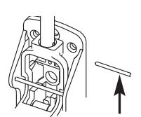
Rod adjustment pin
TOP ROD / CENTER CASE
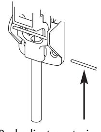
Rod adjustment pin
BOTTOM ROD / CENTER CASE
A7827E 6/22
Surface Vertical Rod Exit Device
Installation Instructions Manual

12 Adjust Top & Bottom Rods
Adjust top and bottom latch bolts for maximum engagement.
Rough adjustments are made by changing the hole used for the adjustment pin.
For Fine adjustments: Turn rod into top and bottom cases to shorten, or turn rod out of top and bottom cases to lengthen.
Top Rod: Push on the door and the rail at the same time. As soon as the door opens, release the rail. The top bolt should be in the hold back position. If not, extend the top bolt.
Note : Top bolt must go into hold back position before the door opens.
Bottom Rod: Extend the bottom bolt for maximum engagement with bottom strike.When the top bolt is in hold back, it also holds the bottom bolt in the retracted position. When the bottom bolt is retracted, the bolt must clear the bottom strike by 1/8" minimum through the swing of the door.
When adjustment is completed, install top and bottom rod guides at midpoint between center and top and bottom chassis, using (2) #10-24 x 1-1/4" oval head screws per guide.
Install center chassis cover using (4) #8-32 x 5/16" screws.
13 Rail Lengths & Cutting Instructions
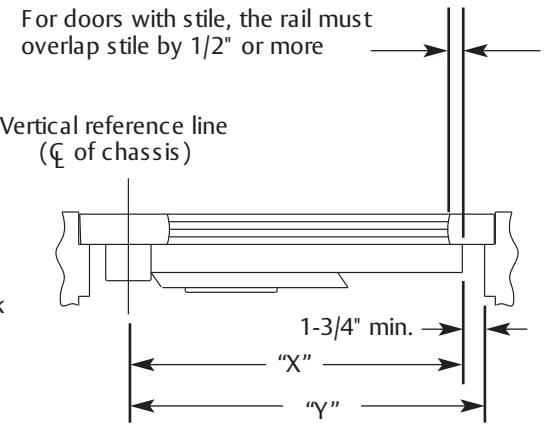
TOP VIE W OF E XIT DE VIC E
| R AIL | MAX DOOR WIDTH | MIN DOOR WIDTH |
|---|---|---|
| E | 32" | 24" |
| F | 36" | 33" |
Determine rail length dimension "X" by subtracting 1-3/4" from dimension "Y".
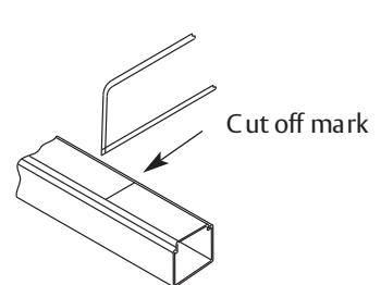
- 1. Dog push rail and cut off at mark.
- 2. C ut must be straight.
- 3. F or (43-) flush end cap use cutting guide provided.
- 4. Remove sharp edges with file.
Surface Vertical Rod Exit Device
Installation Instructions Manual

14 Fire-Rated Single Door, Thermal Pin Template 4628
11
The ASSA ABLOY Group is the global leader in access solutions. Every day we help people feel safe, secure and experience a more open world.