Edwards Signaling Data Sheet K85001-0611 – Analog Addressable Input-Output Modules
Open the original PDF document
View PDF

R O T A R Y ADDRESSING
Technology that saves lives
Intelligent Input-Output Modules
Models: FX-2WIRE, FX-IDC1A, FX-IDC2B, FX-IDCWS, FX-ISO, FX-NAC, FX-RLY, FX-IDC1B
Overview
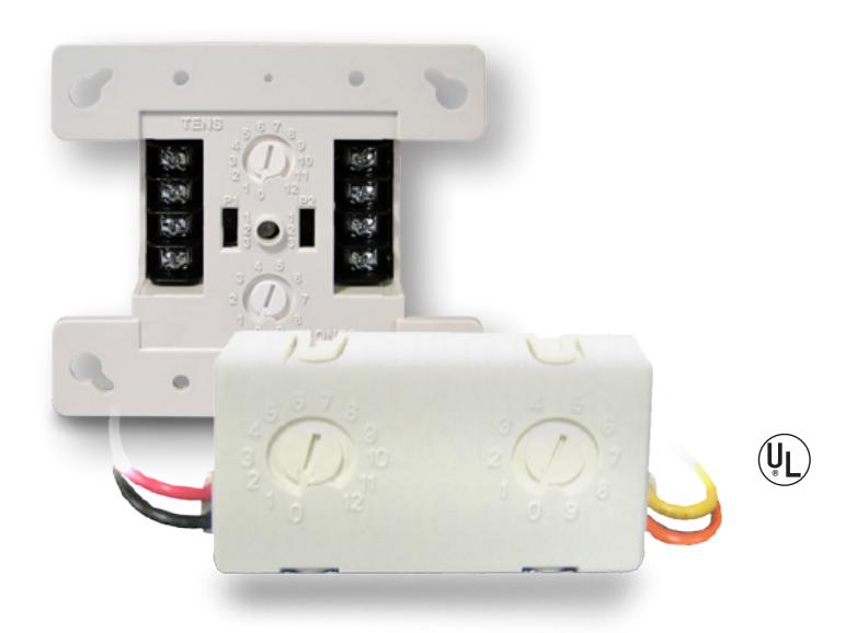
Kidde intelligent modules are engineered to deliver high-performance features, superb reliability, and unbeatable quality. From control of ancillary equipment, to enhanced signaling functionality, these products add flexibility and powerful options to Kidde intelligent systems.
Designed expressly for small buildings, Kidde modules are addressable devices that are uniquely identified on the system by means of familiar rotary switches. Once registered, they share data and update status information that determines how the system behaves and how connected devices interact with one another.
Unique to Kidde modules is ground fault detection so precise that it actually pinpoints the specific module where the wiring problem has occurred. This saves hours of troubleshooting and wire tracing. And only Kidde provides this important feature!
The Kidde family of intelligent modules also offers contractors and installers simple setup and installation, while delivering options that take full advantage of intelligent fire alarm processing. With a microprocessor in each device, intelligence is distributed throughout the system so that command decisions are made instantly at the individual module, rather than bottlenecking at the control panel.
This not only speeds event processing, it also makes a more robust and reliable system – so robust, in fact, that when upgrading from a conventional panel to a Kidde intelligent system, you can usually use existing wiring – no twisted or shielded cable required!
Standard Features
• Class A-B Two-Wire Module
Acts as an interface between conventional two-wire smoke detectors and the Kidde control panel.
• Analog Class A Single Input Module
Used to connect a normally open, alarm, supervisory, or monitor type dry contact initiating device circuit to the Kidde control panel.
• Analog Dual Input Module
Connects two normally open, alarm, supervisory, or monitor type dry contact initiating device circuits to the Kidde control panel.
• Analog Dual Input Waterflow, Supervisory Module
Used to connect normally open waterflow alarm and supervisory initiating device circuits to the Kidde control panel. For Class B circuit operation.
• Analog SLC Fault Isolator Module
Protects a Class A SLC from total collapse due to wire-to-wire short circuits.
• Analog NAC Module
Connects a supervised output circuit to a signal riser.
• Analog Contact Relay Module
Provides one Form C dry relay contact and can be configured to provide polarity reversal of its output.
• Analog Single Input Mini Module
Connects a normally open, alarm, supervisory, or monitor type dry contact initiating device circuit (IDC) to the Kidde control panel. For Class B circuit operation.
Module Addressing
Use a screwdriver to adjust the two rotary switches on the front of the module. Set the TENS rotary switch (0 through 12) for the 10s digit and the ONES rotary switch for the 0 through 9 digit.
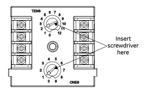
Example: device address 21, set TENS rotary switch to 2 and set the ONES rotary switch to 1.
Refer to the Specifications Table for available address numbers.
LED operation
Modules provide a bicolor LED for status indication.
Flashing Green LED Normal Flashing Red LED Active
Installation
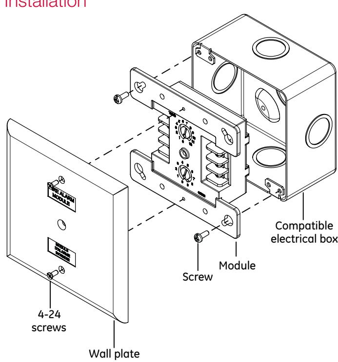
Mount in a North American 4 inch square x 2-1/2 in. (64 mm) deep 2 gang box or a standard 4 in. square box 1-1/2 in. (38 mm) deep.
Class A Single Input Module FX-IDC1A
The Class A Single Input Module is used to connect a normally open, alarm, supervisory, or monitor type dry contact initiating device circuit (IDC) to the Kidde control panel. The module is designed for Class A circuit operation.
The module's device address is set using the two rotary switches located on the front of the module. One device address is required.
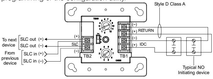
The device can be preset for alarm or supervisory operation using the slide switch located on the front of the module. The module can also be configured for other device types through front panel programming or the configuration utility.
Warning
This module will not operate without electrical power. As fires frequently cause power interruption, you should discuss further safeguards with your local fire protection specialist.
This module does not support conventional smoke detectors.
| Communication line voltage | Maximum 20 V peak-to-peak | |
| Current | ||
| Standby | 400 μA | |
| Activated | 500 μA | |
| Ground fault impedance | 10 k ohm | |
| Operating environment | ||
| Temperature | 32 to 120°F (0 to 49°C) | |
| Humidity |
0 to 93% RH, noncondensing at 90°F
(32°C) |
|
| Storage temperature range | –4 to 140°F (–20 to 60°C) | |
| Compatible electrical boxes | North American 4 inch square x 2-1/2 | |
| in. (64 mm) deep 2 gang box | ||
| Standard 4 in. square box 1-1/2 in. (38 | ||
| mm) deep box | ||
| Wire size | 12, 14, 16, or 18 AWG wire (2.5, 1.5, | |
| 1.0, or 0.75 sq. mm) (Sizes 16 and 18 | ||
| AWG are preferred) | ||
| Device address | 01 to 64 (64 point control panel) | |
| 01 to 127 (1000 point control panel) | ||
| Initiating device circuit (IDC) | ||
| Max. circuit resistance | 50 Ω (25 Ω per wire) | |
| Max. circuit capacitance | 0.1 μF | |
Caution
Wire in accordance with NFPA 72 and CAN/ ULC-S524. Be sure to observe the polarity of the wires as shown in the diagram.
Class A-B Two-Wire Module
The FX-2WIRE module interfaces between conventional two-wire smoke detectors and the Kidde control panel. It monitors the circuit and smoke detectors, and signals the control panel of any trouble or alarm conditions. The module also regulates and supervises the 24 VDC input power.
The FX-2WIRE is configured to operate as a two-wire alarm device that does not require alarm verification. It can be set for two-wire alarm verified operation through front panel programming or the configuration utility. When using the alarm verification feature of the control panel, do not mix normally open contact initiating devices with two-wire conventional smoke detectors.
This module recognizes the CleanMe signal from detectors that support this feature.
The device address is set using the two rotary switches located on the front of the module. One device address is required.
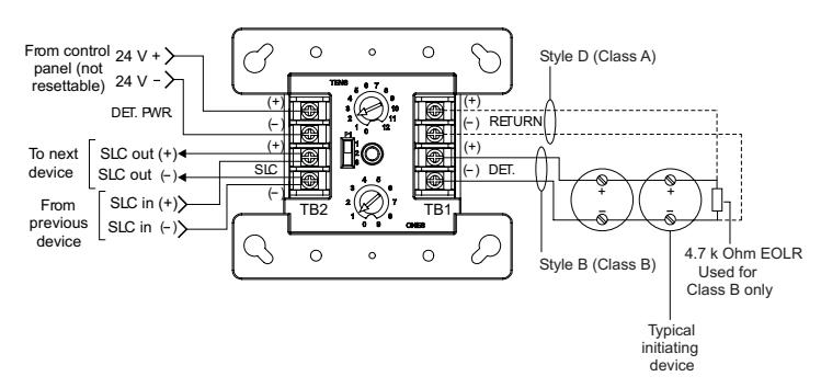
The FX-2WIRE can be set for Class B or Class A operation using the slide switch located on the front of the module.
Note: This module cannot be used on a device loop with isolator modules or isolator bases.
| Communication line voltage | Maximum 20.6 V peak-to-peak | |
| Current | Standby: 350 µA. Activated: 350 µA | |
| Control panel input power | 12.4 to 28.3 VDC (not resettable) | |
| Smoke power current | Standby: 17 mA. Alarm: 58 mA | |
| Smoke detector current | 3 mA | |
| UL compatibility ID | 0.0 | |
| Ground fault impedance | 5 k ohm | |
| Operating environment | ||
| Temperature | 32 to 120°F (0 to 49°C) | |
| Humidity | 0 to 93% RH, noncondensing at 90°F | |
| (32°C) | ||
| Storage temperature | -4 to 140°F (-20 to 60°C) | |
| Compatible | North American 4 inch square x | |
| electrical boxes | 2-1/2 in. (64 mm) deep 2 gang box. | |
| Standard 4 in. square box 1-1/2 in. (38 | ||
| mm) deep | ||
| Wire size | 12, 14, 16, or 18 AWG wire (2.5, 1.5, | |
| 1.0, or 0.75 sq. mm) (Sizes 16 and 18 | ||
| AWG are preferred) | ||
| Device address | 01 to 64 (64 point control panel) | |
| 01 to 127 (1000 point control panel) | ||
| Initiating device circuit | ||
| EOL resistor value | 4.7 kΩ, (P/N: EOL-4.7) | |
| Max. circuit resistance | 50 (25 per wire) | |
| Max. circuit capacitance | 0.1 μF | |
Dual Input Module
The FX-IDC2B connects two normally open, alarm, supervisory, or monitor type dry contact initiating device circuits (IDCs) to the Kidde control panel. This module is designed for Class B circuit operation.
The device address is set using the two rotary switches located on the front of the module. Two consecutive addresses are required. The second address is automatically assigned one number higher than the value set on the rotary switches.
The FX-IDC2B can be preset for alarm or supervisory operation using the slide switch located on the front of the module. It can also be configured for other device types through front panel programming or the configuration utility.
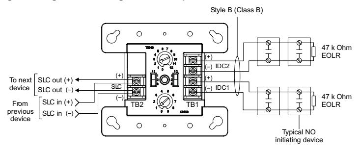
FX-IDC2B
| Communication line voltage | Maximum 20 V peak-to-peak |
|---|---|
| Current | |
| Standby | 550 μΑ |
| Activated | 725 µA |
| Ground fault impedance | 10 k ohm |
| Operating environment | |
| Temperature | 32 to 120°F (0 to 49°C) |
| Humidity | 0 to 93% RH, noncondensing at 90°F (32°C) |
| Storage temperature range | –4 to 140°F (–20 to 60°C) |
| Compatible electrical boxes | North American 4 inch square x 2-1/2 in. (64 mm) deep 2 gang box Standard 4 in. square box 1-1/2 in. (38 mm) deep |
| Wire size | 12, 14, 16, or 18 AWG wire (2.5, 1.5, 1.0, or 0.75 sq. mm) (Sizes 16 and 18 AWG are preferred) |
| Device address | 01 to 63 (64 point control panel) 01 to 126 (1000 point control panel) |
| Initiating device circuit (IDC) | |
| EOL resistor value | 47 kΩ, (P/N: EOL-47) |
| Max. circuit resistance | 50 (25 per wire) |
| Max. circuit capacitance | 0.1 μF |
Dual Input Waterflow, Supervisory Module FX-IDCWS
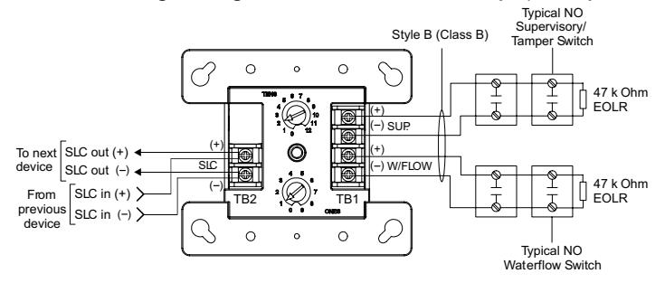
The FX-IDCWS connects normally open waterflow alarm and supervisory initiating device circuits (IDCs) to the Kidde control panel. The FX-IDCWS is designed for Class B circuit operation.
The device address is set using the two rotary switches located on the front of the module. Two consecutive addresses are required. The second address is automatically assigned one number higher that the value set on the rotary switches.
The FX-IDCWS can operate in the following modes:
Waterflow
• Alarm latching delayed: Configures the module for use with only nonretarded waterflow alarm switches. When the NO input contact of an initiating device is closed, an alarm is sent to the control panel, which after a 16 second time delay, generates an alarm signal.
Supervisory
- Supervisory active nonlatching US marketplace
- Supervisory active latching Canadian marketplace
- • Nonlatching: Configures the module for normally open dry
- contact initiating devices. When the NO input contact of an initiating device is closed, a supervisory signal is sent to the control panel and the supervisory condition is not latched at the module.
- • Latching: Configures the module for normally open dry contact initiating devices. When the NO input contact of an initiating device is closed, a supervisory signal is sent to the control panel and the supervisory condition is not latched at the module.
| Communication line voltage | Maximum 20 V peak-to-peak |
| Current | |
| Standby | 550 μA |
| Activated | 725μA |
| Ground fault impedance | 10 k ohm |
| Operating environment | |
| Temperature | 32 to 120°F (0 to 49°C) |
| Humidity | 0 to 93% RH |
| Storage temperature range | –4 to 140°F (–20 to 60°C) |
| Compatible electrical boxes | North American 4 inch square x 2-1/2 |
| in. (64 mm) deep 2 gang box | |
| Standard 4 in. square box 1-1/2 in. | |
| (38 mm) deep | |
| Wire size | 12, 14, 16, or 18 AWG wire (2.5, 1.5, |
| 1.0, or 0.75 sq. mm) (Sizes 16 and | |
| 18 AWG are preferred) | |
| Device address | 01 to 63 (64 point control panel) |
| 01 to 126 (1000 point control panel) | |
| Initiating device circuit (IDC) | |
| EOL resistor value | 47 kΩ, (P/N: EOL-47) |
| Max. circuit resistance | 50 Ω (25 Ω per wire) |
| Max. circuit capacitance | 0.1 μF |
SLC Fault Isolator Module FX-ISO
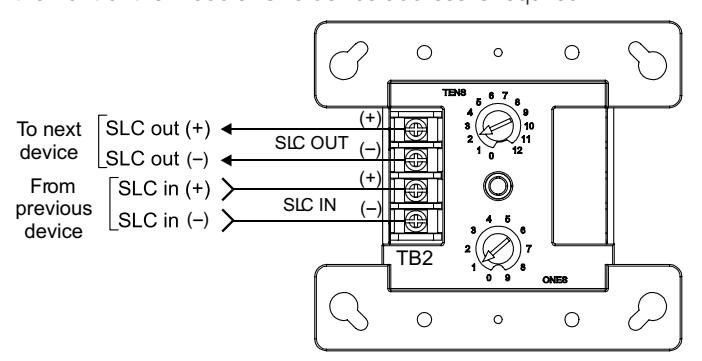
The FX-ISO protects a Class A SLC from total collapse due to wire-to-wire short circuits. The module monitors line voltages and opens the SLC when a short is detected. A short is isolated between the two modules located electrically closest to the short.
The device address is set using the two rotary switches located on the front of the module. One device address is required.
| Communication line voltage | Maximum 20 V peak-to-peak |
| Current | |
| Standby | 175 μA |
| Activated | 200 μA |
| Ground fault impedance | 10 k ohm |
|
Maximum circuit resistance
between isolators |
6 ohm |
| Operating environment | |
| Temperature | 32 to 120°F (0 to 49°C) |
| Humidity | 0 to 93% RH, noncondensing at 90°F |
| (32°C) | |
| Storage temperature range | –4 to 140°F (–20 to 60°C) |
| Compatible electrical boxes | North American 4 inch square x 2-1/2 |
| in. (64 mm) deep 2 gang box | |
| Standard 4 in. square box 1-1/2 in. | |
| (38 mm) deep | |
| Wire size | 12, 14, 16, or 18 AWG wire (2.5, 1.5, |
| 1.0, or 0.75 sq. mm) (Sizes 16 and 18 | |
| AWG are preferred) | |
| Module address | 01 to 64 (64 point control panel) |
| 01 to 127 (1000 point control panel) |
NAC Module
The FX-NAC connects a supervised output circuit to a signal riser. The output wiring is monitored for open and short circuits. A short circuit causes the module to inhibit the activation of the audible/visual signal circuit so the riser is not connected to the wiring fault. Upon command from the control panel, the module connects the output circuit to the riser input. The output circuit energizes a riser to operate polarized audible and visual signals. The module can be used for connection of a Class A or Class B (with EOL) output notification appliance circuit (NAC).
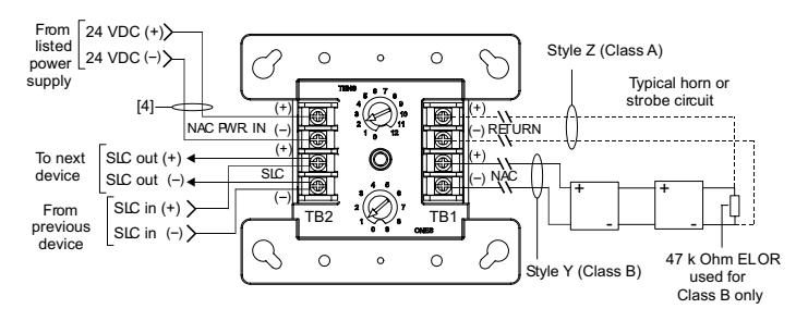
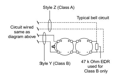
The FX-NAC is configured to operate as a Genesis Audible/Visual/ Silence device type from the factory. It can also be configured for other device types through front panel programming or the configuration utility. Refer to the applicable control panel technical reference manual for a list of available device types.
Genesis Audible/Visual/Silence: Used with Genesis and Enhanced Integrity horns and strobes. Signals maintain synchronization per UL 1971. For Genesis devices, this configuration allows connected horns to be silenced while strobes on the same two-wire circuit continue to flash until the panel is reset.
| Communication line voltage | Maximum 20 V peak-to-peak |
| Current | |
| Standby | 350 µA |
| Activated | 200 μΑ |
| Ground fault impedance | 10 k ohm |
| Operating environment | |
| Temperature | 32 to 120°F (0 to 49°C) |
| Humidity | 0 to 93% RH, noncondensing at 90°F (32°C) |
| Output ratings | |
| Circuit current | 24 VDC at 2 A max. |
| EOL resistor value | 47 kΩ UL listed |
| Storage temperature range | –4 to 140°F (–20 to 60°C) |
| Compatible electrical boxes | North American 4 inch square x 2-1/2 in. (64 mm) deep 2 gang box Standard 4 in. square box 1-1/2 in. (38 mm) deep |
| Wire size | 12, 14, 16, or 18 AWG wire (2.5, 1.5, 1.0, or 0.75 sq. mm) (Sizes 16 and 18 AWG are preferred) |
| Device address | 01 to 64 (64 point control panel) |
| (one address required) | 01 to 127 (1000 point control panel) |
Contact Relay Module
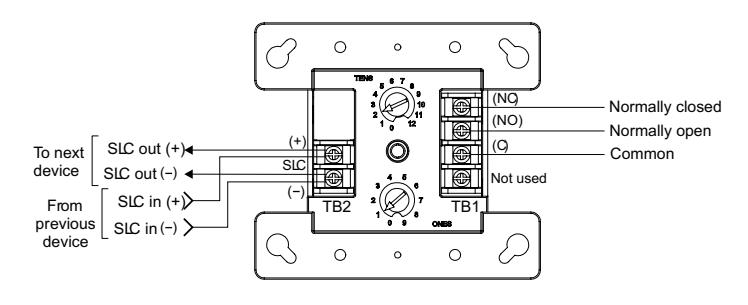
The FX-RLY provides one Form C dry relay contact. It can also be configured to provide polarity reversal of its output. The FX-RLY can be used to control external appliances or shut down equipment.
The FX-RLY is wired according to its operation. It is configured to operate as a relay nonsilence device type, and can function as either a control relay or polarity reversal relay, depending on how it is wired.
Control relay function: Provides one Form C dry relay contact.
Polarity reversal relay function: Provides polarity reversal of its output.
Note: Additional device types are available through front panel programming or the configuration utility. Refer to applicable control panel technical reference manual.
FX-RLY
| Communication line voltage | Maximum 20 V pook to pook | |
|---|---|---|
| Communication line voltage | Maximum 20 V peak-to-peak | |
| Current | 1054 | |
| Standby | 125 µA | |
| Activated | 125 μΑ | |
| Contact ratings (pilot duty) | 0.4 | |
| 30 VDC | 2 A | |
| 125 VAC | 0.5A resistive load 60 W or 62.5 VA max. | |
| Relay type | Form C, programmable | |
| Ground fault impedance | 10 k ohm | |
| Operating environment | ||
| Temperature | 32 to 120°F (0 to 49°C) | |
| Humidity | 0 to 93% RH, noncondensing at 90°F (32°C) | |
| Storage temperature range | -4 to 140°F (-20 to 60°C) | |
| Compatible electrical boxes | North American 4 inch square x 2-1/2 in. (64 mm) deep 1 gang box North American 4 inch square x 2-1/2 in. (64 mm) deep 2 gang box Standard 4 in. square box 1-1/2 in. (38 mm) deep box | |
| Wire size | 12, 14, 16, or 18 AWG wire (2.5, 1.5, 1.0, or 0.75 sq. mm) (Sizes 16 and 18 AWG are preferred) | |
|
Module address
(one address required) |
01 to 64 (64 point control panel)
01 to 127 (1000 point control panel) |
|

Technology that saves lives
Contact us...
Email: kidde.fire@fs.utc.com Web: <u>www.kiddefx.kidde.com</u>
Kidde is a UTC brand. 1016 Corporate Park Drive Mebane, NC 27302
© 2016 United Technologies Corporation. All rights reserved.
Single Input Mini Module
FX-IDC1B
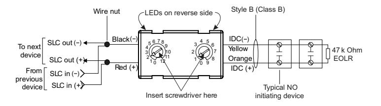
The FX-IDC1B connects a normally open, alarm, supervisory, or monitor type dry contact initiating device circuit (IDC) to the Kidde control panel. This module is for Class B circuit operation.
The device address is set using the two rotary switches located on the front of the module. One device address is required.
The module is configured to operate as an alarm latching device type from the factory. When the NO contact of an initiating device is closed, an alarm signal is sent to the control panel and the alarm condition is latched at the module.
Additional device types are available through front panel programming or the configuration utility. Refer to applicable control panel technical reference manual.
| Communication line voltage | Maximum 20 V peak-to-peak |
|---|---|
| Current | |
| Standby | 350 μΑ |
| Activated | 500 μΑ |
| Ground fault impedance | 10 k ohm |
| Operating environment | |
| Temperature | 32 to 120°F (0 to 49°C) |
| Humidity | 0 to 93% RH, noncondensing at 90°F (32°C) |
| Storage temperature range | -4 to 140°F (-20 to 60°C) |
| Wire size | 12, 14, 16, or 18 AWG wire (2.5, 1.5, 1.0, or 0.75 sq. mm) (Sizes 16 and 18 AWG are preferred) |
| Device address | 01 to 64 (64 point control panel) |
| (two addresses required) | 01 to 127 (1000 point control panel) |
| Initiating device circuit (IDC) | |
| EOL resistor value | 47 kΩ, (P/N: EOL-47) |
| Max. circuit resistance | 50 (25 per wire) |
| Max. circuit capacitance | 0.1 μF |
Ordering Information
| Model | Description | Ship Weight |
|---|---|---|
| FX-IDC1A | Analog Class A Single Input Module | 0.50 lbs. (0.23 kg.) |
| FX-IDC1B | Analog Single Input Mini Module | 0.34 lbs. (0.15 kg.) |
| FX-2WIRE | Analog Class A-B Two-Wire Module | 0.50 lbs. (0.23 kg.) |
| FX-IDC2B | Analog Dual Input Module | 0.50 lbs. (0.23 kg.) |
| FX-2IDCWS | Analog Dual Input Waterflow-Supervisory Module | 0.50 lbs. (0.23 kg.) |
| FX-NAC | Analog NAC Module | 0.50 lbs. (0.23 kg.) |
| FX-RLY | Analog Contact Relay Module | 0.50 lbs. (0.23 kg.) |
| FX-ISO | Analog SLC Fault Isolator Module | 0.50 lbs. (0.23 kg.) |