Edwards Signaling 970519 Technical Bulletin
Open the original PDF document
View PDF

Edwards Signaling Products 90 Fieldstone Court Cheshire, CT 06410 (203) 699-3300 FAX (203) 699-3108
Technical Bulletin # 970519 Date: June 1, 1999 Product: Message Centers
Product Category: Allen-Bradley® SLC-5/03 Connectivity
Subject: How to display text messages from an A-B SLC-5/03 PLC
This technical bulletin will show a way to connect your message center to an Allen-Bradley® SLC-5/ 03 PLC. This method uses A-B's RS-Logix 500® revision 2.10.12.0 to generate the ladder logic and employs text commands from the message center protocol. The message center will be sent a text string from an output file of the PLC using the AWT command. This text string will contain certain commands leading the actual message displayed and other commands lagging the message. These commands are from the message center communications protocol and control the message parameters.
SECTION I: Hardware Connections
Connect your SLC-5/03 PLC to the Message Center using the Channel 0 RS-232C jack on the face of the processor card. Use an adapter and straight through RS-232 cable as shown in diagram 1. You can also use RS-485 connectivity by employing the converter box as shown in diagram 2.
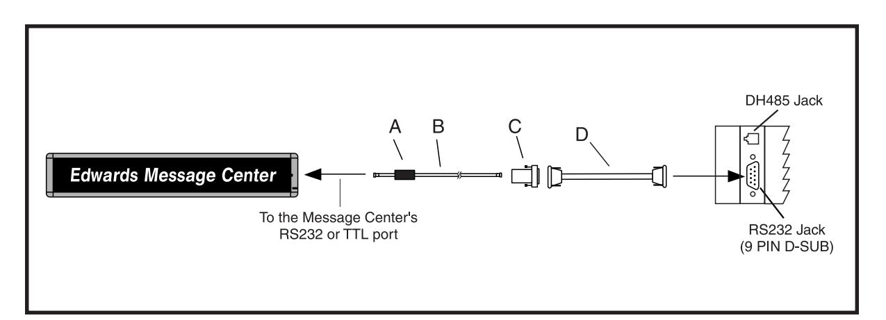
Diagram 1
| Item | Cat. No. | Description |
|---|---|---|
| A | — | Ferrite (ferrite end towards sign) |
| B | MCN232-RJ11-25 | 25 foot, 6-conductor RS-232 cable |
| MCN232-RJ11-50 | 50 foot, 6-conductor RS-232 cable | |
| C | MCN2329FRJ11 | 9 Pin D-Sub/to 6 pos RJ11 adapter |
| D | MCN485CB232A9 | 10 foot 9 pin-to-9pin type A9 RS232 cable |
NOTE: Set internal message center jumper to RS232
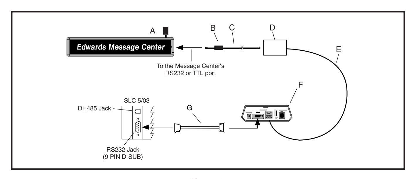
Diagram 2
| Item | Cat. No. | Description |
|---|---|---|
| A | MCN485EOLTCB | EOL Termination |
| B | — | Ferrite (ferrite end towards sign) |
| C | MCN232-RJ11-8 | 8 foot, 4-conductor RS-485 cable |
| MCN485-RJ11-1 | 1 foot, 4-conductor RS-485 cable | |
| D | MCNMNARJ11485 | Modular network adapter |
| E | MCN485-1000 | 1000 foot spool of RS485 cable |
| F | MCN485CB2EOLT | Converter box w/2 EOL terminators |
| G | MCN485CB232A9 | 10 foot 9 pin-to-9 pin type A9 RS232 cable |
NOTE: Set internal message center jumper to RS485
SECTION II: Software Configuration
To configure the RS-Logix 500 software for communications with the Message Center, set the following under Project/Controller/Channel Configuration/Channel 0 User:
Mode: ASCII Baud: 9600 Parity: None Stop Bits: 1 Start Bits: 8
In addition, under Project/Controller/Channel Configuration/General, set the Channel 0 mode to User.
SECTION III: Message Center Setup
There are only a few things needed to set up the Message Center to receive text strings from the PLC. Set up the Message Center for the appropriate communications method RS-232 or RS-485 as shown in the installation manual for the message center. (Set the internal jumper to RS-232 or RS-485 position as needed). Next, Clear the sign's memory (See Section VI) and setup the desired serial address using the remote control.
SECTION IV: Format for the AWT Command:
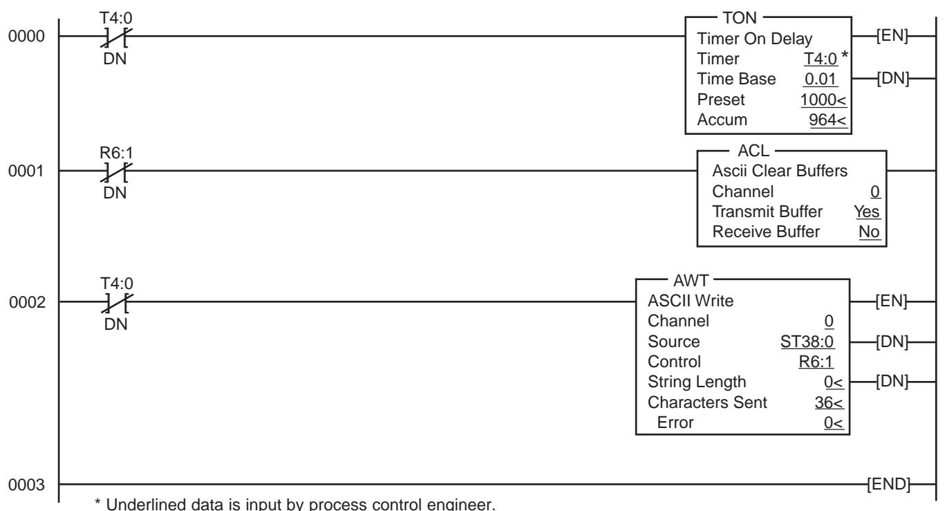
Use the AWT instruction to write characters from a source string file to an external device. Example of Instruction (Parameters shown are examples only, your data will vary) follows:
Entering Parameters
Channel - is the number of the RS-232 port (must be 0)
Source - is the string element you want to write.
Control - is the area that stores the control register required to operate the instruction.
String Length - (.LEN) is the number of characters you want to write from the source string (0-82). If you enter a 0, the entire string will be written. This is Word 1 in the control block.
Characters Sent - (.POS) are the number of characters that the processor sent to the display area (0-82). This field is continuously updated during the execution of the instruction. This value can be greater than the string length if appended characters or inserted values are used. If the string length is greater than 82 the string written to the destination will be truncated to 82 characters. This is Word 2 in the control block.
Error - the hexadecimal error code that indicates why the ER bit was set in the control data file. Refer to ASCII Error Codes in RsLogix's help manual for an explanation of any displayed error code.
Command Operation
- 1. The AWT rung goes from false-to-true, setting the EN (Enable) bit.
- 2. The instruction is put in the ASCII queue, setting the EU (Queue) bit.
- 3. The instruction executes and the RN (Run) bit is set.
- 4. Forty characters are sent from the source string through channel 0.
- 5. The DN (Done) bit is set and a value of 40 is present in .POS word of the ASCII control block.
- 6. When the program scan finds the DN bit set, the processor sets the EM (Synchronous Done) bit.
Execution Errors
The ER (Error) bit is set during the execution of the instruction if the modem is disconnected (control line selection is other than NO HANDSHAKING), or the port is in System mode and is configured for DH485, or the UL (Unload) bit is set.
Sample Ladder Program
Below is a simple ladder program that sends a single text message to a Message Center. The timer T4, in this example, is used to repeat the transmission every 10 seconds. This would normally be replaced with an "examine input or bit" type command. For this example, the source string location is ST38 in element 0 (ST38:0). This is the location where the single text message is stored. Other source string locations can be used simultaneously for multiple message transmissions. For example, a ladder program may consist of multiple rungs, with each rung having its own "examine input" and "AWT" command. If any one of the rungs go true, the rung's AWT command would execute sending out the appropriate source string. For simplicity, the example shown here uses only one source string.
SECTION V: Text String Format Hardware Connections
An ASCII text message can be placed in a source file by going into the RSLogix 500 Data Files Folder and double clicking on the associated source file called out in the AWT command. A message can easily be constructed by typing directly in ASCII to the appropriate data source file. Listed below is a sample string that tells an Edward's Message Center to display the following text and format : "Electrician and Supervisor please report to cell #3 " with Fill text, Red text color, normal font, in hold text mode. The sign's serial address in this example is 01.
Note - every message will have special preamble and trailing characters to denote the start and stop of a text message to the message center. Each message string should begin with five NUL (0h) characters for auto-baud detect of serial data sent to the message center. Messages should follow the text format outlined below:
<NUL><NUL><NUL><NUL><NUL><SOH>[Type Code][Serial Addr]<STX>[CMD Code][File Label][Control Characters][Data Field]<EOT>
Message example 1:
\00\00\00\00\00^AZ01^BAA\1B0b\1C1Electrician and Supervisor please report to cell #3^D
Where:
| \00\00\00\00\00 |
Five consecutive
|
|
|---|---|---|
| ^A |
|
|
| Z | ASCII Type Code for All Message Centers in network | |
| 01 | 2 Byte ASCII-Hex Message Centers Address (see note 1) | |
| ^B |
|
|
| A | Command code A, Write a TEXT File to the Message Centers | |
| A | File Label A name | |
| \1B |
The
|
|
| 0 |
Display position. An ASCII Zero (30h) will fill all available lines, centering
the lines vertically. (see note 2) |
|
| b | A control character that denotes holding the text in place | |
| \1C1 |
A control character that tells the Message Centers to use Red text. (see
note 3) |
|
|
Electrician and Supervisor
please report to cell #3 |
The text that will appear on the Message Centers | |
| ^D |
The
every message string. |
|
Notes:
- (1) This is a two byte ASCII to hexadecimal representation of serial address (00 to FF is the hex range) or 0 to 256 decimal. If 00 is used for serial address, then all signs on the network will respond to the string.
-
(2) On one-line Message Centers, the display Position is irrelevant, but still must be included. The following ASCII characters can be used for display position:
- 0 Fill the Message Center with all available lines centered vertically.
- " " Start text in the middle of the Message Center.
- " Start text on the top line.
- & Start text on the bottom line
- (3) For Message Centers that support colors the following control characters can be used for text color: for red only message centers this code can be omitted.
| \1C1 | Red | \1C7 | Orange |
|---|---|---|---|
| \1C2 | Green | \1C8 | Yellow |
| \1C3 | Amber | \1C9 | Rainbow 1 |
| \1C4 | Dim Red | \1CA | Rainbow 2 |
| \1C5 | Dim Green | \1CB | Color Mix |
| \1C6 | Brown | \1CC | Auto-color |
(4) Other codes are available to change font size and are message center model dependent. See section VII.
SECTION VI: Sample Strings
| Message Action | String Required |
|---|---|
| Flash Red Message | \00\00\00\00\00^AZ01^BAA\1B0c\1C1HARD HATS REQUIRED^D |
| Flash Green Message | \00\00\00\00\00^AZ01^BAA\1B0c\1C2HARD HATS REQUIRED^D |
| Steady Red Message | \00\00\00\00\00^AZ01^BAA\1B0b\1C1HARD HATS REQUIRED^D |
| Steady Green Message | \00\00\00\00\00^AZ01^BAA\1B0b\1C2HARD HATS REQUIRED^D |
Notes:
- 1. In order for text " hold " or other features to properly work, Message Centers should have the "Auto-mode" disabled. This can be done one time, directly from the remote control, in "Program" mode, or can be sent serially via note 2 clear memory.
- 2. The serial string to clear memory is: \00\00\00\00\00^AZ01^BE$AAU0100FD00^D This string sets the message centers's memory configuration for File Label A, Text File A, Unlocked, File Size 0100h (256 bytes), Start Time = FD (Run message All day), Stop Time = 00 and <EOT>
SECTION VII: Additional Support
For questions please call our tech support line 203-699-3300. Additional codes are available for controlling message center text strings in our Communications Protocol available from your local Edwards Signaling representative.
Allen-Bradley® is a registered trademark of Rockwell Automation Inc. RS-Logix 500® is a registered trademark of Rockwell Automation Inc.