Edwards Signaling 93 94 and 97 Series Installation Instructions
Open the original PDF document
View PDF

Cheshire, CT 06410 203-699-3300 (Ph) 203-699-3365 (Cust. Serv. Fax) 203-699-3078 (Tech. Serv. Fax)
Installation Instructions for Catalog Series 93, 93DF, 94, 94DF, 97 and 97DF AdaptaBeacon® Signals
Description
The catalog series 93, 94 and 97 AdaptaBeacon signals are UL and cUL listed strobe lights suitable for indoor or outdoor (weatherproof) installation. A hardware kit is included with the 97 series signals for direct surface mounting applications.
The 93 and 94 series are ac powered; the 97 series signals are dc powered. These signals are also available in double flash versions (denoted by DF in the catalog numbers). Voltage and current ratings for all models are shown in Electrical Specifications.
Replacement Parts for the signals are available. Refer to Table 1 for details.
Electrical Specifications
|
Catalog
Number |
Rated
Voltage |
Current |
|---|---|---|
| 93(*)-N5 | 120V 50/60 Hz | 0.10 Amp |
| 93(*)-R5 | 240V 50/60 Hz | 0.05 Amp |
| 93DF(*)-N5 | 120V 50/60 Hz | 0.10 Amp |
| 93DF(*)-R5 | 240V 50/60 Hz | 0.05 Amp |
| 94(*)-N5 | 120V 50/60 Hz | 0.10 Amp |
| 94(*)-R5 | 240V 50/60 Hz | 0.05 Amp |
| 94DF(*)-N5 | 120V 50/60 Hz | 0.10 Amp |
| 94DF(*)-R5 | 240V 50/60 Hz | 0.05 Amp |
| 97(*)-EK | 12 - 48V DC | 1.20 Amp |
| 97(*)-MP | 75 - 125V DC | 0.20 Amp |
| 97(*)-S1 | 250V DC | 0.10 Amp |
| 97DF(*)-EK | 12 - 48V DC | 1.20 Amp |
| 97DF(*)-MP | 75 - 125V DC | 0.20 Amp |
* The letter (A - amber, B - blue, C - clear, G - green, M - magenta or R - red) in this position signifies the color the supplied lens.
Installation

WARNINGS
To prevent electrical shock, ensure that power is disconnected before installing the signal.
To prevent leakage and potential electrical shock, use care when disassembling the signal to prevent tearing of the permanently affixed gaskets provided for weatherproofing.

CAUTIONS
To prevent damage to the strobe tube, lift the lens straight up and off of the signal.
To prevent damage to the strobe tube, handle the strobe tube only by the base.
-
1. Disassemble the signal using one of the following applicable procedures.
- a. 93 and 97 Series: Refer to Figure 1. Except for the voltage ratings, the 93 and 97 series are identical. Remove the three screws from the skirt, grasp the lens and lift the lens/skirt straight up off of the base. Then, remove the three screws holding the strobe tube support plate to the signal base; grasp the socket (on the strobe tube support plate) and carefully lift the support plate off of the signal base. Proceed to step 2.
- b. 94 Series: Refer to Figure 2. Remove the three screws and the rubber gaskets (washers) holding the protective dome to the signal base. Lift the dome and its rubber gasket straight up off of the signal base. Then loosen the three screws in the keyhole slots in the base of the lens, turn the lens clockwise and lift it off of the strobe tube support plate. Next, remove the three screws holding the strobe tube support plate to the signal base; grasp the socket (on the strobe tube support plate) and carefully lift the support plate off of the signal base. Proceed to step 2.
- 2. The 93 and 94 series signals are conduit mounted. The 97 series can be conduit mounted or direct surface mounted. Install the signal base using one of the following applicable procedures.

WARNINGS
To prevent leakage and a potential shock hazard, when mounting outdoors the signal must be installed with the lens or dome facing directly up.
Conduit Mounting
- a. Route the field wiring from the appropriate power source for the signal through 3/4" (19 mm) NPT conduit and through the conduit entrance hole in the signal base. Refer to Figure 1 for the 93 and 97 series signals and Figure 2 for the 94 series.
- b. Install the signal base on the conduit and proceed to step 3.
Direct Surface Mounting (97 Series Signals Only)
- a. Remove the three outer knockouts from the bottom of the signal base. The location of the knockouts corresponds to the three outer holes in the gasket provided in the direct mounting hardware kit shown in Figure 3.
- b. Place the 7 3/8" (187 mm) mounting gasket on the mounting surface and mark the center of the four holes in the gasket on the surface. Refer to Figure 3. Remove the mounting gasket and drill a 3/8" (9.5 mm) hole at each of the marked positions.
- c. Install the three rubber expansion plugs provided in the hardware kit into the three outer holes in the mounting surface as indicated in Figure 4.
- d. Route the wiring from the required power source for the signal (refer to signal's label for voltage rating) through the center hole in the mounting surface, mounting gasket and signal base. Use a suitable means to protect the wiring from chafing in the hole.
- e. Align the holes in the mounting gasket with the holes in the signal base. Insert the three screws with lockwashers (provided in the hardware kit) through the three mounting holes inside the signal base and align the screws with the rubber expansion plugs as shown in Figure 4. Press the signal base firmly against the mounting surface and tighten the screws. Proceed to step 3.
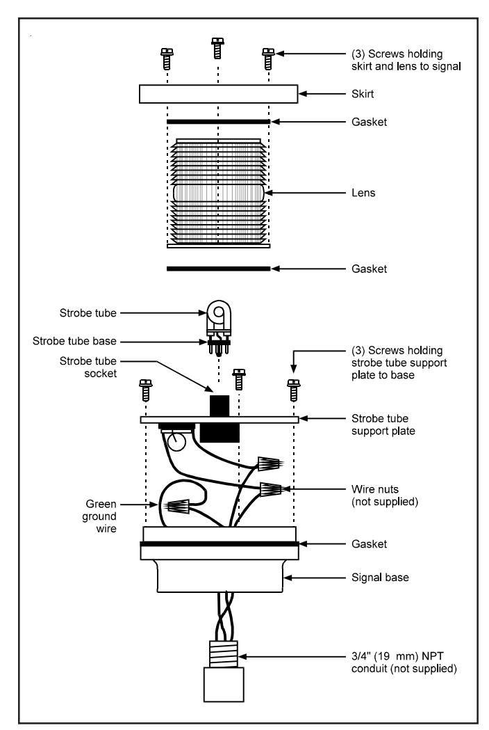
Figure 1. Conduit Mounting of 93 and 97 Series Signals
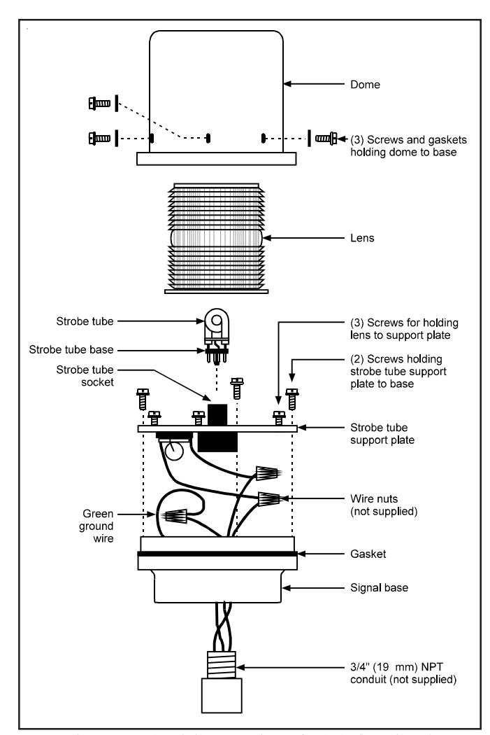
Figure 2. Conduit Mounting of 94 Series Signal
-
3. Connect field wiring to signal wiring.
- a. 93 and 94 Series: Connect the field wiring to the signal's wire leads, using wire nuts (not supplied). Polarity is not important. Connect the green ground wire leads using wire nuts (not supplied).
- b. 97 Series: Connect the field wiring to the signal's wire leads using wire nuts (not supplied) as follows. Polarity must be observed. Connect the red positive (+) wire lead to the positive power source wire and connect the signal's white negative (-) wire lead to the negative power source wire.
- 4. Place the connected wires inside the signal base and reassemble the signal.
- 5. Turn on the power and verify that the signal operates properly.
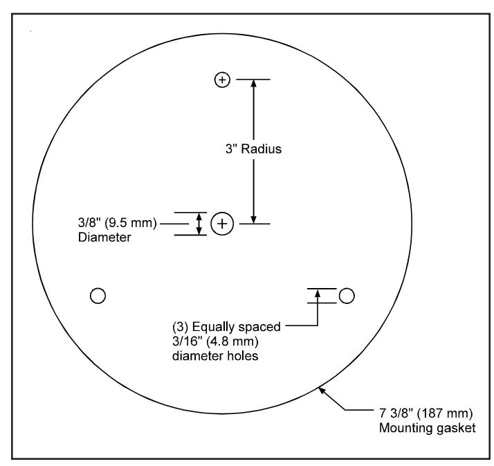
Figure 3. Mounting Gasket for Direct Surface Mounting of 97 Series Signals
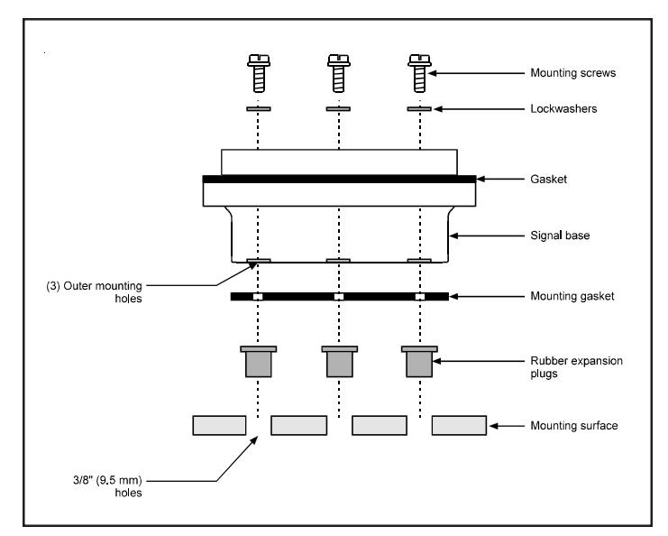
Figure 4. Direct Surface Mounting of 97 Series Signals
Maintenance

WARNINGS
To prevent electrical shock, disconnect power and allow five (5) minutes for stored energy to dissipate before disassembling the signal.
To prevent leakage and potential electrical shock, use care when disassembling the signal to prevent tearing of the permanently affixed gaskets provided for weatherproofing.
Cleaning

CAUTION
To prevent damage to the lens and dome, do not use abrasive materials or cleaners.
Periodically clean the signal lens and dome (as applicable) to maintain optimum light visibility. These items may be cleaned with a soft cloth or sponge using water or a mild detergent solution. Ensure that the lens and dome are completely dry before replacing.
Strobe Tube Replacement
Refer to Table 1 for the required strobe tube.
-
1. After disconnecting the power and waiting five minutes, replace the strobe tube as follows:
- a. 93 and 97 Series: Refer to Figure 1. Remove the three screws from the skirt, grasp the lens and lift the skirt and the lens straight up off of the signal base. Proceed to step 2.
- b. 94 Series: Refer to Figure 2. Remove the three screws and the rubber gaskets holding the protective dome to signal base. Lift the dome and rubber gasket off the signal base. Loosen the three screws in the keyhole slots in the base of the lens, turn the lens clockwise and lift it straight up off the strobe tube support plate. Proceed to step 2.

CAUTION
To prevent damage to the strobe tube, handle the strobe tube only by the base.
- 2. Grasp the base of the strobe tube and pull firmly, or carefully pry between the strobe tube base and the socket, to remove the tube from the socket. Install the new strobe tube by aligning the key on the strobe tube base with the slot in the socket and then pressing the strobe tube base onto the socket. Reassemble the signal.
- 3. Turn on the power and verify that the strobe operates.
Table 1. Replacement Parts Replacement parts for the 93, 94 and 97 series signals are available from your local Edwards distributor.
| Component | Used On |
Catalog or
Part Number |
|---|---|---|
| Xenon Strobe Tube | All series | 92-ST |
| Dome (Clear) | 94 Series | 94-DC |
| Lens (Amber, Blue, Clear, Green, Magenta or Red) | All series | 93-L(*) |
* Specify color of lens by adding one of the following letters to the catalog number or part number: A - amber, B - blue, C - clear, G - green, M - magenta, or R - red.
P-047550-0943 OFFSET SPEC
ADAPTABEACON SIGNALS SERIES 93, 93DF, 94, 94DF, 97 AND 97DF INSTALLATION INSTRUCTIONS FOR CATALOG
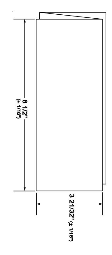
TAIL WITH PART NUMBER ON THE OUTSIDE. THREE TIMES TO DIMENSIONS SHOWN ON DE- (1) 11" X 17" SHEET PRINTED BOTH SIDES. FOLD
MATERIAL: STANDARD WHITE OFFSET STOCK
GROUND CHARACTERS: TO BE BLACK ON WHITE BACK-
REDUCED TO ACTUAL SIZE. NOTE: MECHANICALS HAVE ALREADY BEEN
CHESHIRE, CT 06410 90 FIELDSTONE COURT EDWARDS SIGNALING TECHNICAL WRITING RETURN MECHANICALS TO:
FOLD DETAIL REFERENCE ONLY
ECN: 03-C1662 Issue: 07
File: FCF120 Approved by: KRT