Edwards Signaling 5541M Series Installation Instructions
Open the original PDF document
View PDF

Installation and Operation of the Catalog Number 5541M-Y6 Millennium System Master
DEVELOPED BY EDWARDS SIGNALING
COPYRIGHT NOTICE
© 2003
IMPORTANT IMFORMATION
Limitation of liability
This product has been designed to meet the requirements of Underwriters Laboratories, Inc., Standard 2017 and 864. Installation in accordance with this manual, applicable codes, and the instructions of the Authority Having Jurisdiction is mandatory. The manufacturer shall not under any circumstances be liable for any incidental or consequential damages arising from loss of property or other damages or losses owing to the failure of products beyond the cost of repair or replacement of any defective products. The manufacturer reserves the right to make product improvements and change product specifications at any time.
While every precaution has been taken during the preparation of this manual to ensure the accuracy of its contents, the manufacturer assumes no responsibility for errors or omissions.
FCC Warning
This equipment has been tested and found to comply with the limits for a Class A digital device, pursuant to part 15 of the FCC Rules. These limits are designed to provide reasonable protection against harmful interference when the equipment is operated in a commercial environment. This equipment generates, uses, and can radiate radio frequency energy and, if not installed and used in accordance with the instruction manual, may cause harmful interference to radio communications. Operation of this equipment in a residential area is likely to cause harmful intereference in which case the user will be required to correct the interference at his own expense.
Compliance Statement
Millennium System Master, when properly installed, operates with a Local Protected Premises Fire Alarm System in accordance with the following standard:
• Underwriters Laboratories Standard 864
Millennium System Master, when properly installed, can also be configured to operate as a self-monitored evacuation device, in accordance with the following standard:
• Underwriters Laboratories Standard 2017
Content
| Chapter 1 | System overview and operation | 1 |
|---|---|---|
| 1.1 | System overview 1 | |
| 1.2 | Operations Review 1 | |
| 1.3 | Controls and Indicators 1 | |
| 1.4 | Operating the Panel 5 | |
| Chapter 2 | Installation | 7 |
| 2.1 | Installation checklist 7 | |
| 2.2 | Installing the cabinet 7 | |
| 2.3 | Installing Power 7 | |
| 2.4 | Wiring a Satellite Panel 10 | |
| 2.5 | Connecting Speaker/Amplifiers 11 | |
| 2.6 | Connecting External Initiating Inputs 11 | |
| 2.7 | Connecting to Output Relay 12 | |
| 2.8 | Connecting External Initiating Input to Fire | |
| Alarm Panel 12 | ||
| 2.9 | Connecting to a UL Listed Telephone Access | |
| Module 13 | ||
| 2.10 | Connecting to Remote Paging Units 14 | |
| 2.11 | Adjusting Audio Levels 15 | |
| Chapter 3 | Programming | 16 |
| 3.1 | Overview 16 | |
| 3.2 | Local Alarm Input Assignment 16 | |
| 3.3 | Relay Output Assignment 16 | |
| 3.4 | Device Commission 16 | |
| 3.5 | Dynamic Zone ControlTM 17 | |
| 3.6 | Communications Setup 17 | |
| 3.7 | Panel Address Assignment 17 | |
| 3.8 | Panel Mode 17 | |
| 3.9 | Auto Learn Mode 17 | |
| 3.10 | Zone to Input Assignment 18 | |
| 3.11 | Voice Message Setup 18 | |
| 3.12 | Standby Power Mode 19 | |
| 3.13 | Remote Programming | |
| 3.14 | Text Output String | |
| 3.15 | Security 19 | |
| Chapter 4 | Maintenance | 20 |
| 4.1 | Preventive Maintenance 20 | |
| 4.2 | Preventive Maintenance Schedule 20 | |
| Chapter 5 | LCD Messages and Troubleshooting | 21 |
| 5.1 | Normal Mode 21 | |
| 5.2 | Troubleshooting and Trouble Messages 22 | |
| Appendix A | Calculations | 26 |
| Battery calculation worksheet 26 | ||
| 5532M Audio amplifier voltage drop calculation 27 | ||
| 5532M Audio am. circuit max. wire length calculation 28 | ||
| Suggested RS-485 Network topology 28 | ||
| Appendix B | Programming template | 29 |
| Appendix C | Panel specifications | 30 |
| Appendix D | Wiring | 31 |
Chapter 1 - System Overview and Operation
1.1 - System overview
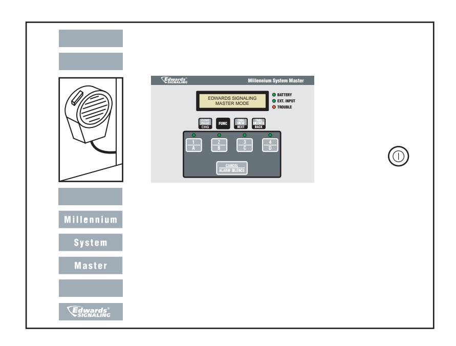
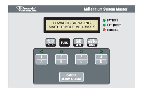
The Millennium System Master is a Four Zone Emergency Evacuation and Routine Signaling control panel that can be programmed to operate in two mode types: Master Mode or Satellite Mode. In either mode, the panel provides reliable emergency and non-emergency notification. In addition to signaling notification, the panel provides area and plant wide voice communications for emergency and non-emergency use. See Figure 1.
The following features are built in:
- 67 field selectable audible tones (See Table 1)
- · Audio, voice & power supervision
- Microphone and input supervision
- Up to 4 five-second field recordable voice messages
- · Hand-held microphone paging
- Standby power by using EBPS10 Booster Power Supply
- Up to 64 Satellite units addressable through RS485 network
- Output & Trouble Relays designed for fail-safe operation
- Multiple knockouts for easy cabinet entry
- · LED Alarm & Status Indication
- 40 character LCD display for system status messages
- Program lockout key
- Adjustable output volume control
- Text output capable with Edwards message center signs
1.1.1 - Master Mode
In Master mode, the panel will be in standby normal operation waiting for either emergency or non-emergency keypad or external initiation. While there is no keypad or external initiation, the panel will perform continuous supervision on the following: RS-485 network via serial polling of configured devices, audio signal output wires, external input channels, remote power loss sense, microphone, audio amplifier and STDBY power input (when enabled). Any encountered troubles will be posted both visually, on the panel's LCD screen, and audibly from the panel's internal piezo buzzer.
During panel initiation of emergency and non-emergency activity, supervision (with the exception of RS-485 polling) will occur after 30 seconds of operation from the start of the initiation request. Polling will continue regardless of the panel's activity state.
1.1.2 - Satellite Mode
When in this mode, the panel will operate the same as in Master mode, except it will not supervise RS-485 network devices. It may, however, respond to serial commands from another panel configured as a master. All supervisory updates will occur once every 30 seconds.
1.2 - Operations overview
In the absence of any alarm, supervisory trouble, or non-emergency events, the control panel monitors the entire system for integrity.
When panel encounters either an emergency or non-emergency event, the panel conducts the following:
- Energizes appropriate output relays (K1-K4) associated with programmed input
- Activates programmed alarm tone/voice audio output
- Enables the appropriate alarm LED on the front panel
- Runs the appropriate programmed output response for the local or external input that signaled the event
- Communicates programmed Dynamic Zone Control event information to appropriate serial devices (Master Mode only)
1.3 - Controls and Indicators
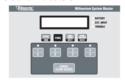
(1) Function Buttons
Button Description

In Setup mode: changes currently selected program variable to next available program variable.
From Master/Satellite mode: Initiates zone paging menu.

From Master/Satellite mode: Selects panel setup mode.

From Setup mode: Selects next program function.
In Setup mode: Selects next available input or output to be programmed or assigned.
From Master/Satellite: Allows viewing of current trouble condition(s).

In Setup mode: changes currently selected program variable to previous selection.
From Master/Satellite: Allows silencing of local trouble buzzer.
(2) Local Alarm Initiating Inputs
Button Description

From Master/Satellite mode: Initiates local alarm program 1 or selects Zone A for local paging. On steady until either CANCEL button is pressed or another local alarm is initiated.
2 B
From Master/Satellite mode: Initiates local alarm program 2 or selects Zone B for local paging. On steady until either CANCEL button is pressed or another local alarm is initiated.
3 C
From Master/Satellite mode: Initiates local alarm program 3 or selects Zone C for local paging. On steady until either CANCEL button is pressed or another local alarm is initiated.

From Master/Satellite mode: Initiates local alarm program 4 or selects Zone D for local paging. On steady until either CANCEL button is pressed or another local alarm is initiated.
PAGE 3 P/N 3100471 ISSUE 3
(2) Local Alarm Initiating Inputs
Button Description
From Master/Satellite mode: Cancels active local alarm program and transmits zone broadcast serial data to serial devices.
From Setup mode: Terminates setup mode and returns panel to normal operation.
(3) Common System LEDs
| LED | Description |
|---|---|
| Alarm |
Flashing Green when there is an active alarm event occurring
on local alarm program inputs. |
| (buttons 1 - 4) | |
| Trouble |
Flashing Red when there is a fault with a monitored circuit or
system component, when in Setup mode or when the panel is in STDBY power mode. |
| EXT Input |
Flashing Green when there is one or more active external
input(s) occurring on the external input channels or if the system audio channel is enabled coming from a Master panel. |
| BATTERY |
Steady Green when the panel has sensed AC
power loss and is on STDBY power |
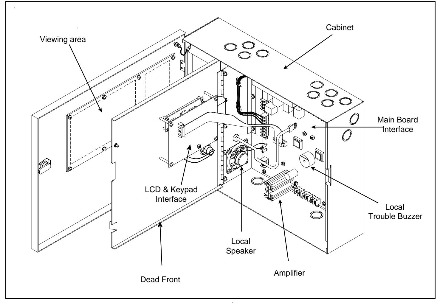
Figure 1. Millennium System Master
1.4 - Operating the Panel
1.4.1 - Resetting the panel
Pressing the RAMM SILENCE button places the panel in the alarm-reset state. The panel should not be reset until the appropriate authority has determined that the hazard is no longer present.
When you reset the panel:
- All local alarm program input LEDs will turn off.
- Active tone/voice audio output is disabled.
- All dynamic zones are disabled (Master panel only).
- All output relays are de-energized.
- Trouble LED will turn off temporarily until supervisory status update is restored. If the panel is configured as Master mode, supervisory status update will occur immediately; if the panel is configured as a Satellite mode, supervisory status will update within 30 seconds. The LED will remain off until it detects system trouble.
- When reset is complete, the local panel buzzer will turn off.
In this state:
- Alarm, trouble, and output relays are returned to the inactive state.
- STDBY POWER detection remains off until supervisory status update resumes.
If at the conclusion of the reset an active external input is detected, the panel will treat the event as a new event and activate the programmed responses.
To reset the panel:
1. Press the CANCEL button.
1.4.2 - Silencing the local panel Trouble buzzer
Pressing the button silences the local buzzer on the panel. While in silence mode, the buzzer will sound once every 10 seconds for 0.5 seconds. This silence mode is restored to continuous mode only after a panel reset.
To silence the panel Trouble buzzer:
- 1. Press the button on the panel.
- Determine the cause of the trouble condition by pressing the button.
1.4.3 - External Input Devices (EID)
External Input Devices (EID) connected to the panel's external input channels cannot be reset from the front panel. If an EID is active and the alarm condition must be cleared, the EID must then be manually reset at the point of origin.

WARNING
The EID should not be disabled until the cause of the alarm is determined and problem is resolved.
Resounding an alarm condition
Pressing the local alarm buttons (1-4) turns the audible devices back on if they were previously disabled or cancelled.
1.4.4 - Performing an Evacuation Drill or Walk Test
You can perform an EVAC drill or Walk Test by simply activating any one of the local alarm buttons. Tone/Voice, output relays and zones associated with the selected alarm button will be enabled. See the programming section for Local Input, Output Relays and Zone assignment. It is recommended that the user reserve a single local alarm button for EVAC drill, Walk Test or both. When programming the local alarm button, all zones and outputs relays should be assigned to this alarm button.
To perform an Evacuation Drill or Walk Test:
- Press the user defined local alarm button.
- 2. To stop the EVAC drill or Walk Test, press the ALARM SILENCE button.
PAGE 5 P/N 3100471 ISSUE 3
THIS PAGE INTENTIONALLY LEFT BLANK
Chapter 2 - Installation
2.1 - Installation checklist
- □ Prepare the site. Make sure the installation location is free from construction dust and debris and extreme temperature ranges and humidity.
- Unpack the equipment.
- ☐ Install the cabinet. See "Installing the Cabinet" for dimensions.
- ☐ Plan wire routing. See Appendix D or the panel label.
A
WARNING
Prior to making any electrical connections, ensure power is disconnected.
- Connect the field wiring. See Appendix D or the panel label. Meter for opens, grounds, and shorts before connecting.
- Connect AC power and ground. See Figure 4 and Appendix D or the panel label.
- □ Connect Standby power. See Figure 5 and Appendix D or the panel label. NOTE: When the System Master is used with a fire alarm panel, Standby Power MUST be installed and enabled.
- □ Program the panel. Refer to Chapter 3.
-
Verify operation.
- 1. Initiate contacts--listen for tones
- 2. Push initiation buttons listen for tones
- 3. Break audio & power leads to test supervision. Panel should go into trouble.
- 4. Adjust audio levels.
- Check program switch is locked, deadfront is installed and door is locked.
2.2 - Installing the cabinet
Cabinets can be surface mounted or semi-flush mounted. See Figure 2 for framing and mounting dimensions.
2.2.1 - Surface Mounting
- 1. Position the cabinet on the finished wall surface.
- Fasten the cabinet to the wall surface where indicated in Figure 2 using (4) 1/4" x 2" lag screws for wood, (4) 1/4" x 1" sheetmetal screws for steel, or (4) 1/4" x 2 1/4" wedge anchors for cement.
2.3 - Installing Power
A
DANGER
High voltage present when power applied. Prior to making any electrical connections, ensure power is disconnected.
- 1. Review specifications Appendix C for power requirements. Provide branch circuit wiring rated for panel requirements.
- Connect green ground wire to terminal "G" on terminal block TB5 (Figures 3 and 4).
- Connect incoming Neutral to terminal "N" on terminal block TB5. Connect incoming Hot to terminal "L" on terminal block TB5 (Figures 3 and 4).
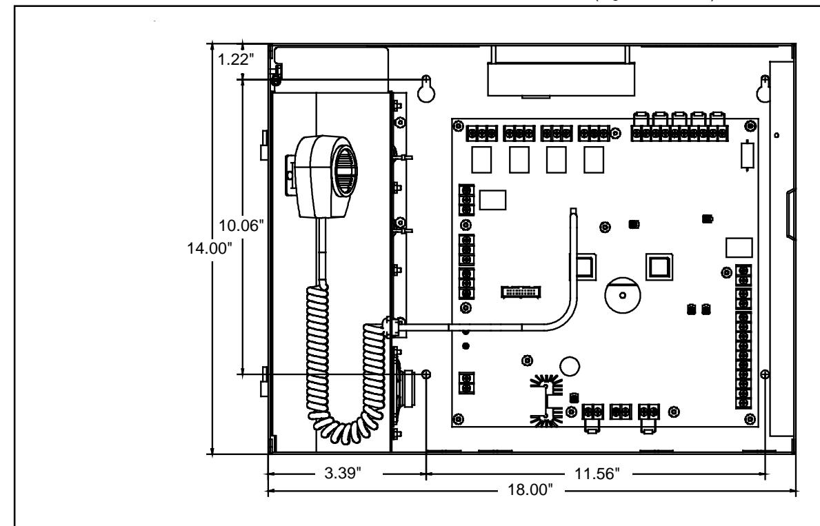
NOTE: System Master Shown without Doors Installed
Figure 2. Panel Dimensions
PAGE 7 P/N 3100471 ISSUE 3
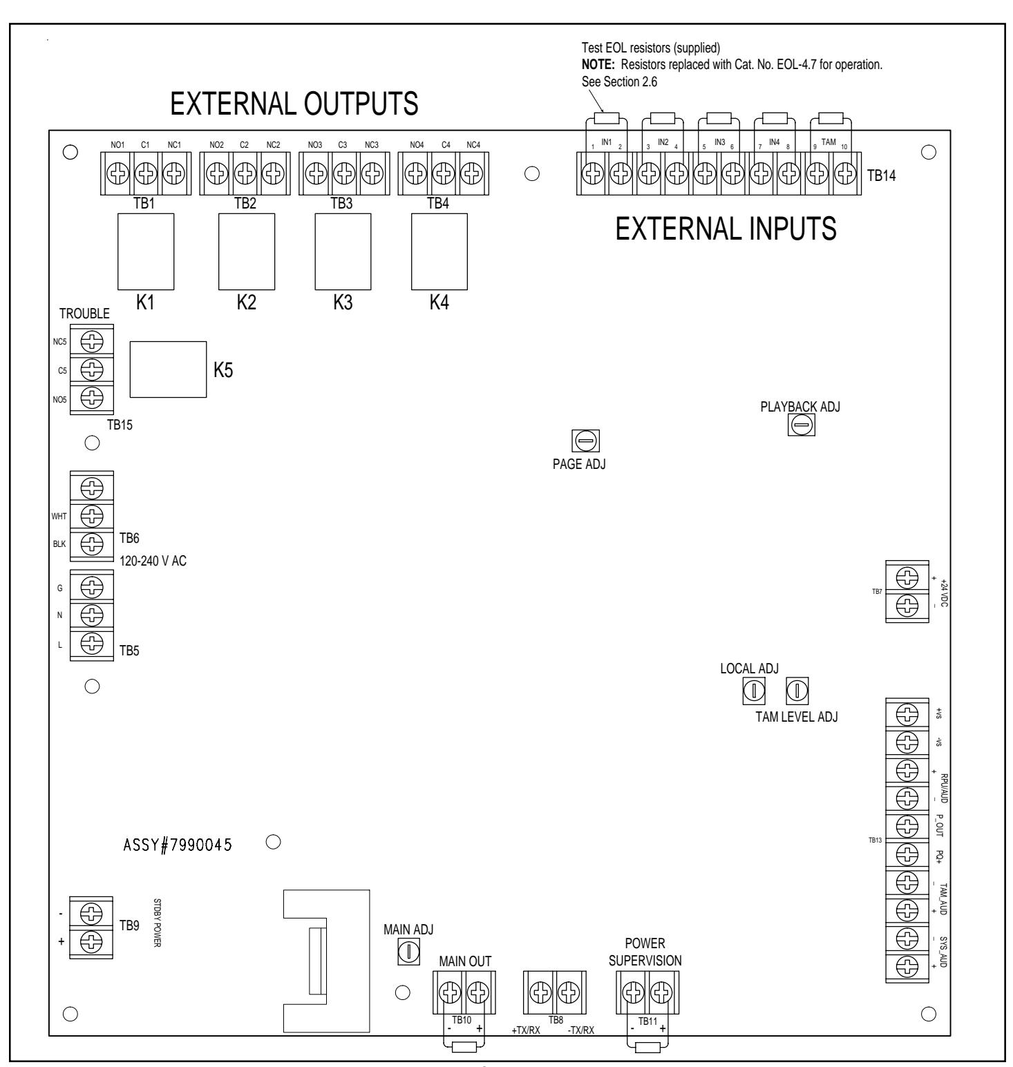
Figure 3. PC Board Locations
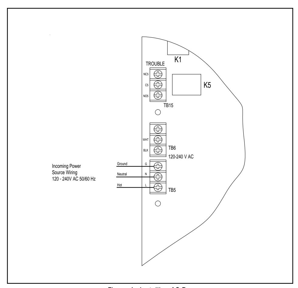
Figure 4. Installing AC Power
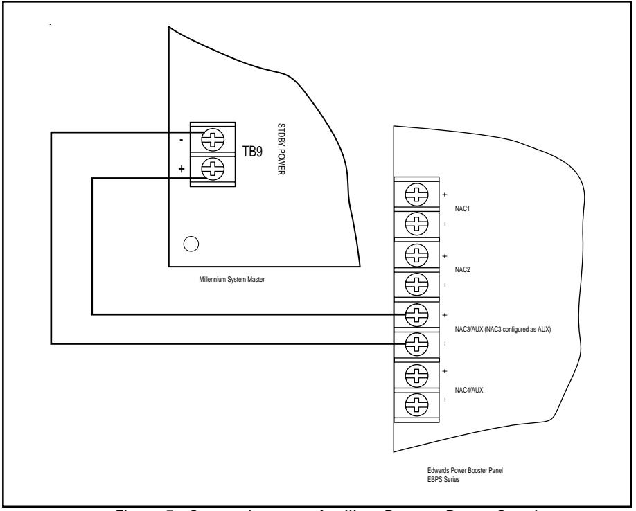
Figure 5. Connecting to an Auxiliary Booster Power Supply
PAGE 9 P/N 3100471 ISSUE 3
2.4 - Wiring a Satellite Panel
The Millennium System Master is capable of driving up to 64 Satellite Panels. Connect the System Masters together as described here (See Figures 3 and 6).
- Connect the RS485 wire from +TX/RX (TB8) on the Master Panel to terminal +TX/RX (TB8) on the Satellite Panel. Connect the RS485 wire from -TX/RX (TB8) on the Master Panel to -TX/ RX (TB8) on the Satellite Panel.
- Connect from MAIN OUT (+) (TB10) on the Master Panel to SYS_AUD (+) (TB13) on the Satellite Panel. Connect from MAIN OUT (-) (TB10) on the Master Panel to SYS_AUD (-) (TB13) on the Satellite Panel ending the loop with a 2.2K ohm end-of-line resistor (Part No. EOL-2.2).
- 3. Speaker/Amplifiers can be connected to the Satellite Panel as described in Section 2.5. NOTE: Speaker/Amplifiers connected to a Satellite Panel are NOT addressable and connections from +TX/RX and -TX/RX are unnecessary.
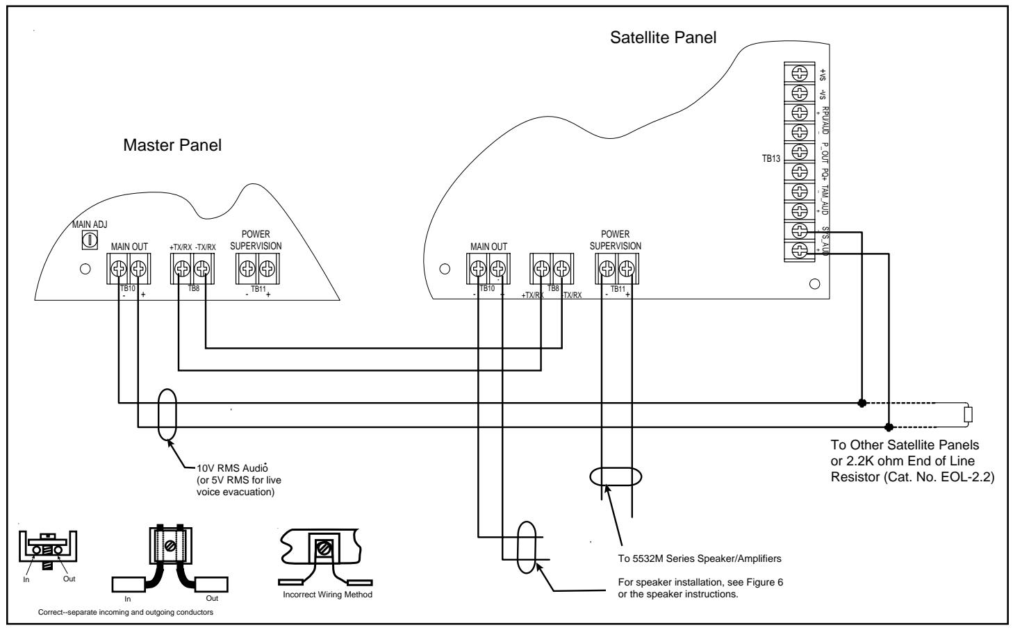
Figure 6. Connecting Satellite Panels to the Master Panel
2.5 - Connecting Speaker/Amplifiers
The Millennium System Master is capable of driving a total of 200 (64 of which can be addressable) 5532M Series speaker/amplifiers. Connect the console to the speaker/amplifiers as described below (See Figures 3 and 7).
- Connect 10V RMS audio line (or 5V RMS for live voice evacuation) from "Main Out" (terminal block TB10) to the first 5532M speaker/amplifier. For connections to the 5532M speaker/amplifier, refer to the instructions supplied with the unit.
- Continue to connect remaining 5532M series speaker/ amplifiers as shown in Figure 7 ending the loop with a 2.2K end-of-line resistor (Part Number EOL-2.2).
- For 5532M-485 Series speaker/amplifiers, connect the RS485 wire from +TX/RX (TB10) on the console board to terminal +TX/RX on the RS485 COMM board. Connect the RS485 wire from -TX/RX (TB10) on the console board to -TX/RX on the RS485 COMM board. For further installation details for 5532M-485 series, refer to installation instructions P/N 3100345.
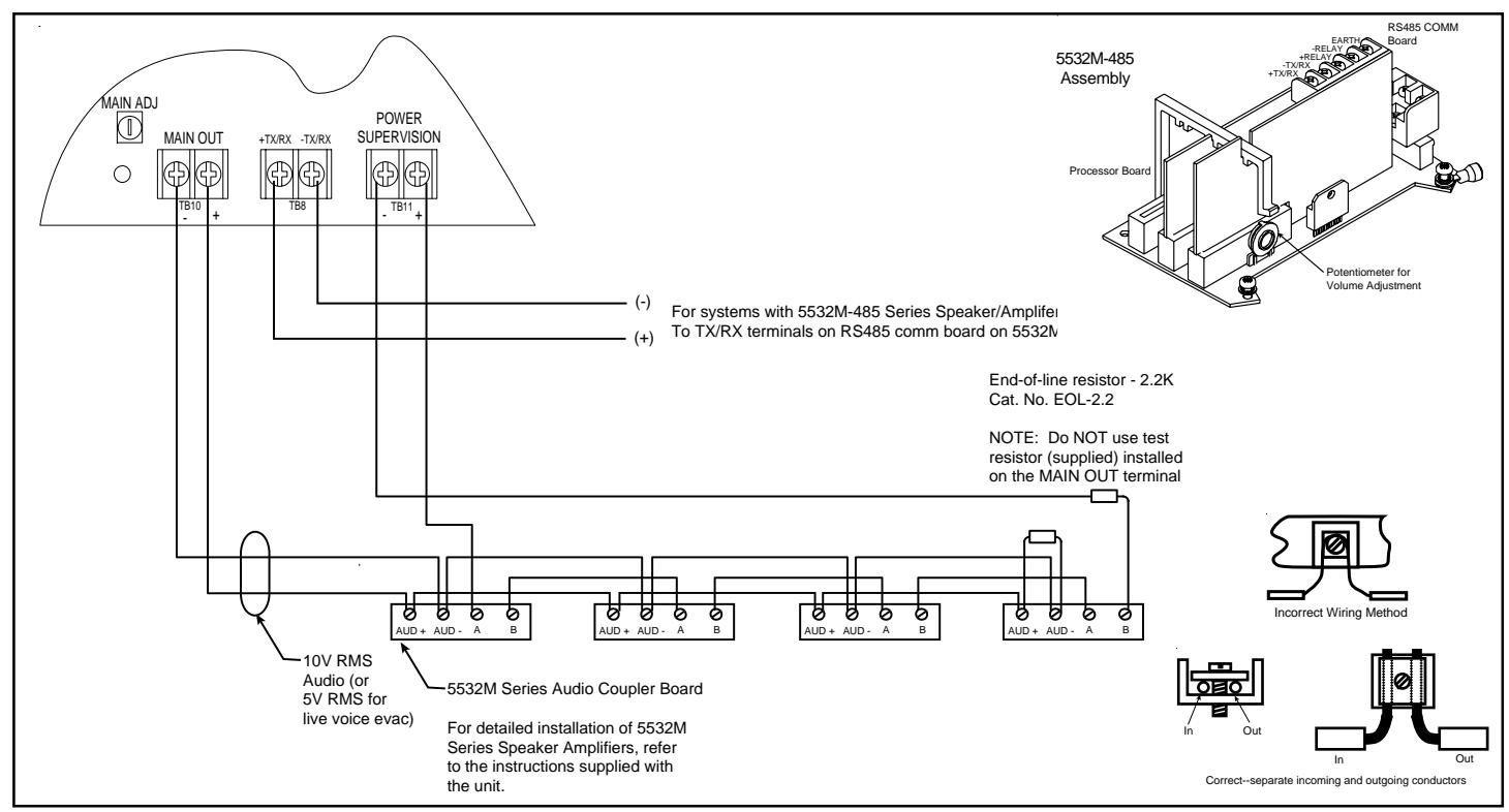
Figure 7. Connecting 5532M Series Speaker/Amplifiers to Audio Main Out
2.6 - Connecting External Initiating Inputs
The initiating contacts operate on a pyramid-type priority system. Output from a contact closure on Input 1 overrides the output from a contact closure on Inputs 2, 3 and 4. The output from a contact closure on Input 2 overrides the output from a contact closure on Inputs 3 and 4. Likewise, the output from a contact closure on Input 3 overrides the output from a contact closure on Input 3 overrides the output from a contact closure on Input 4. The output from a contact closure on Input 4 cannot override the output from any other external input.
- Remove all test resistors from the input terminals. Install 4.7K ohm resistors, Cat. No. EOL-4.7, on terminals that will not have initiating contacts connected to them.
- Connect normally-open initiating contact(s) to input terminals IN1, IN2, IN3, IN4 on External Input terminal block, TB14 (see Figures 3 and 8) as required. Install 4.7K ohm resistors, Cat. No. EOL 4-7, at the end of each circuit as shown in Figure 8.
NOTE: If connecting an external input to a Fire Alarm Panel, refer to Section 2.8.
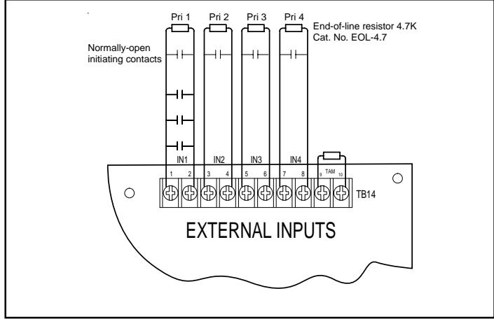
Figure 8. Connecting Normally-Open Initiating Contacts
PAGE 11 P/N 3100471 ISSUE 3
2.7 - Connecting to Output Relay
Up to four loads can be connected to the external output relays. Refer to Figures 3 and 9 for connections and to Appendix C, Panel
Specifications, for maximum contact ratings. Output relays are fail-safe; if the relay coil is faulty, power to the panel is lost or the relay driver fails, the relay, although de-energized, will activate and the load will be energized.
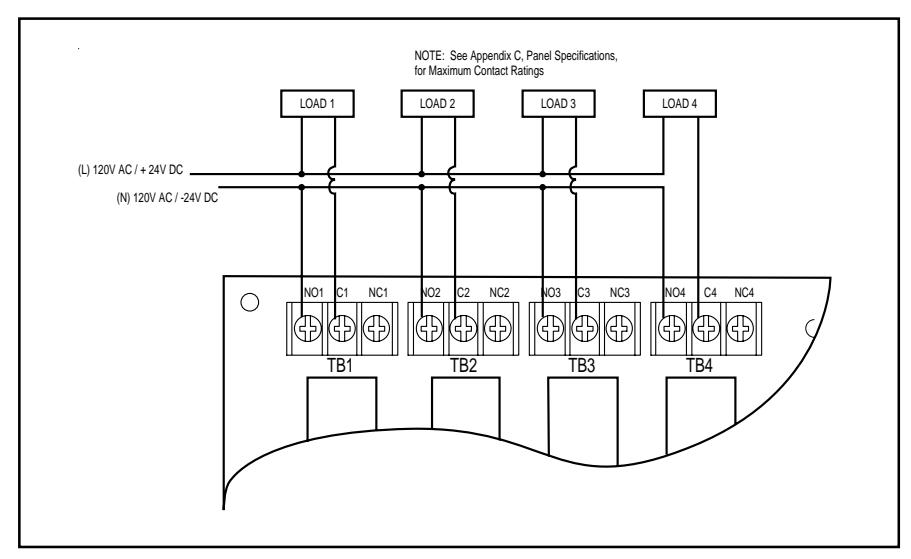
Figure 9. Connecting Output Relays (General Purpose)
2.8 - Connecting External Initiating Input to Fire Alarm Panel
The System Millennium Control Master can be connected to a fire alarm panel for use in evacuation of the building. Connect the fire alarm panel through a Cat. No. 6254B-003 relay to the console as shown in Figure 10.
NOTE: When the System Master is used with a fire alarm panel, Standby Power MUST be installed and enabled.
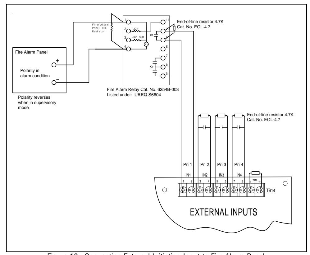
Figure 10. Connecting External Initiating Input to Fire Alarm Panel
2.9 - Connecting to a UL Listed Telephone Access Module
Connect the System Millennium Master to a Telephone Access Module (TAM) as shown in Figure 11. Use only a UL Listed telephone access module with a dry contact initiation and 600 ohm balanced or unbalanced output
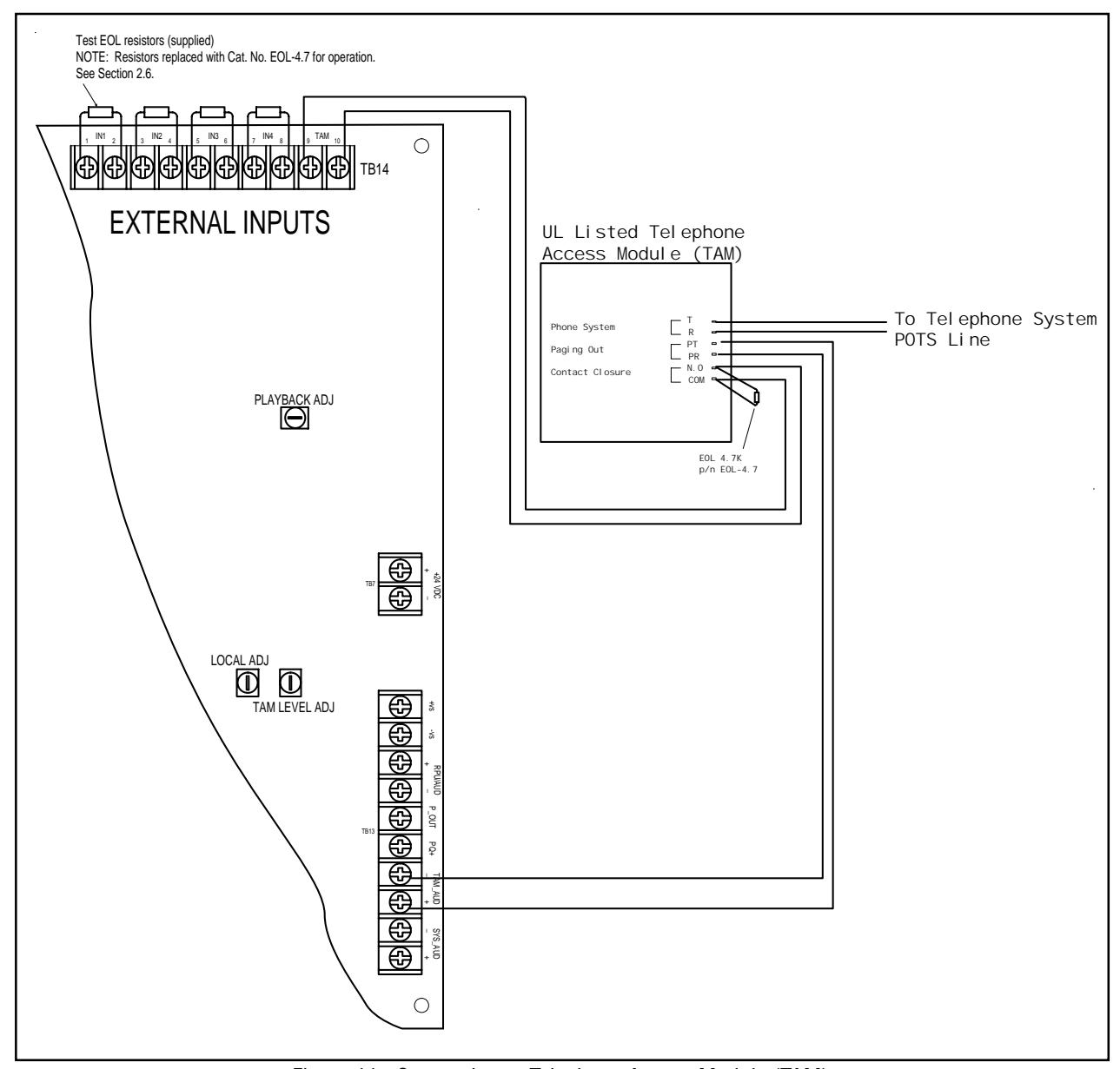
Figure 11. Connecting to Telephone Access Module (TAM)
PAGE 13 P/N 3100471 ISSUE 3
2.10 - Connecting to Remote Paging Units
Up to twenty-five 5542RPUs can be connected to the panel. The first paging unit connected has the highest priority on the system followed by decreasing priorities for the remainder of the 5542RPU paging units connected in series. (Refer to Figures 3 and 12.)
All connections referred to below are made from terminals on terminal block TB13 on the System Master to terminal block TB1 on the 5542RPU.
- Connect from +VS on the System Master to +VS on the 5542RPU.
- Connect from -VS on the System Master to GND on the 5542RPU.
- 3. Connect from RPU/AUD + on the System Master to A+ on the 5542RPU.
- 4. Connect from RPU/AUD on the System Master to A- on the 5542RPU.
- 5. Connect from P_OUT on the System Master to Pin on the FIRST 5542RPU in the series.
- 6. Connect from PQ+ on the System Master to PQ on the 5542RPU.
- 7. Connect from Pout on the first 5542RPU in the series to Pin on the next 5542RPU in the series. Repeat for each 5542RPU in the series.
- 8. For ancillary use only--NOT supervised.
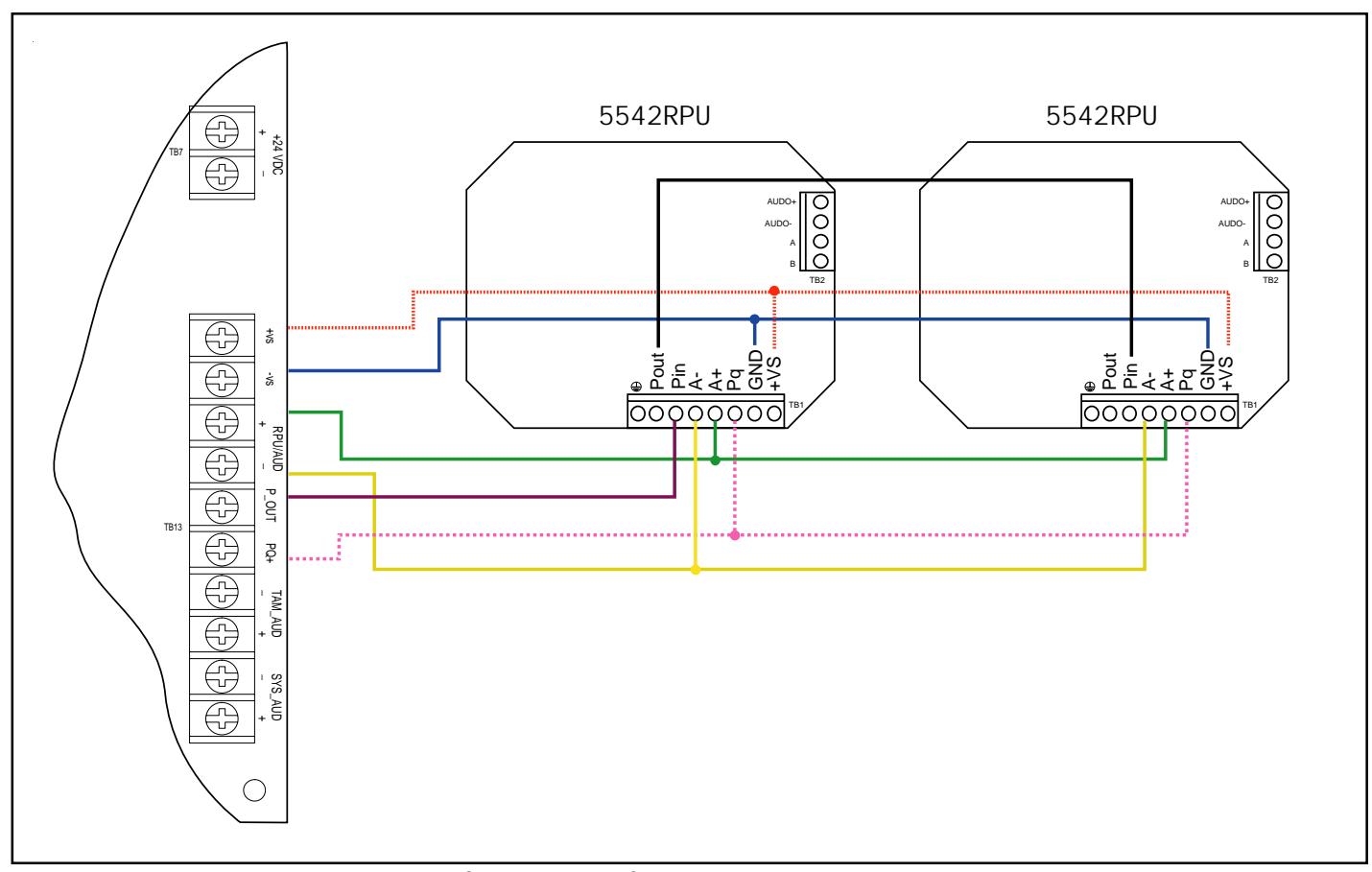
Figure 12. Connecting to a Cat. No. 5542RPU Remote Paging Unit
2.11 - Adjusting Audio Levels
Volume levels can be adjusted for main output, paging, playback, local monitor speaker, and for telephone access module (TAM) audio. Refer to Figure 13 to see locations for potentiometers.
NOTE: Volume increases by turning the potentiometer clockwise.
Page Adjust - Adjusts local microphone level
Playback Adjust - Adjusts voice message level
Local Adjust - Adjusts level of local monitor speaker
<u>TAM Level Adjust</u> - Adjusts level of external telephone audio coming from telephone access module
<u>Main Adjust</u> - Adjusts main system audio out. Needs to be at minimum of 2.5V RMS. Adjusting the main system audio to less than 2.5V RMS will result in a trouble indication.
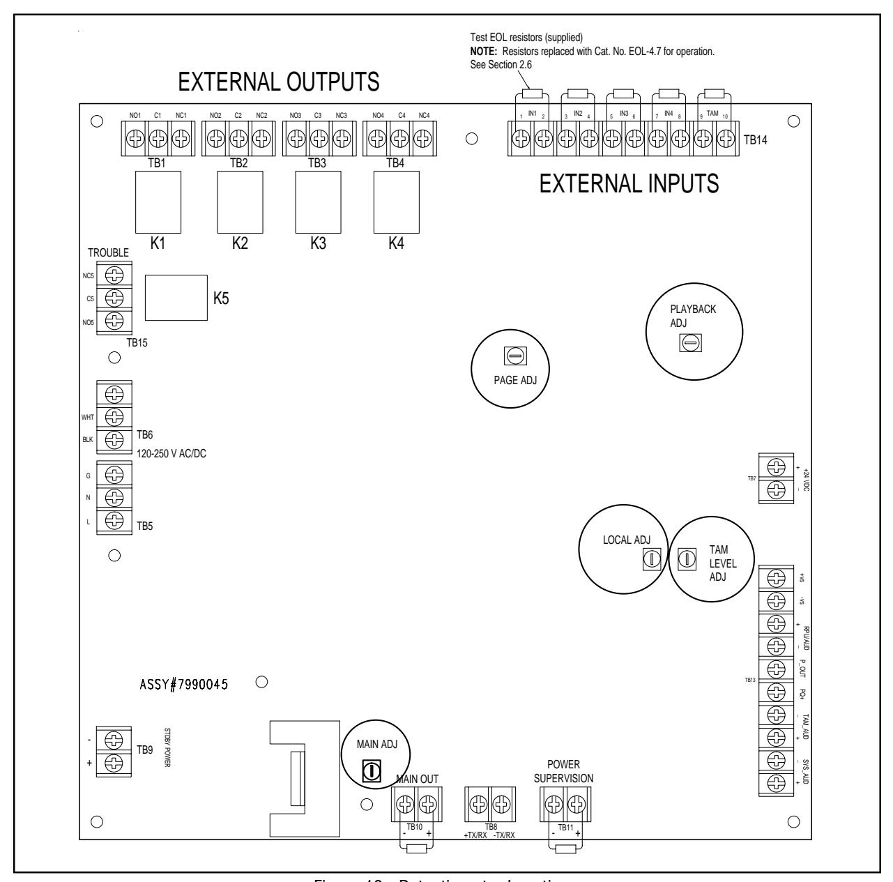
Figure 13. Potentiometer Locations
PAGE 15 P/N 3100471 ISSUE 3
Chapter 3 - Programming
3.1 - Overview
Program options and settings
The features and functions of the Millennium System Master are programmable. To customize the panel, program it as described in this chapter.
Programming Notes
To enable programming, you must insert the key (supplied with the console) into the lock on the inside door (below the LCD panel) and turn it clockwise 90°.
NOTE: The key cannot be removed when programming is enabled.
Pressing at any time during a setup will advance to the next available setup screen.
Pressing (cancel button) at any time during setup mode will exit the setup mode. Pressing cancel will not cancel changes you have made to the panel programming.
The panel will automatically exit setup mode if no buttons are pressed for 60 seconds.
3.2 - Local Alarm Input Assignment
Allows any of the selected tone or voice messages to be programmed to local alarm inputs 1 through 4 located on the front panel.
Tone Label Set Input 01: Tone 02
Using the LCD screen and the tone chart in Table 1 or located on the inside front cover of the panel, press the button to enter the "Setup mode." The LCD displays "Tone Label" with Input 1 and its tone assignment as shown here.
1. Change the tone assignment on Input 1 by pressing the (change button) button until the desired tone is reached.
NOTE: Pressing the (back button) at any time will change the tone selection to the previously selected tone.
- 2. To change the tone assignment on Local Input 2 press the (next button) and repeat step 1.
- 3. To change the tone assignment on Local Inputs 3 and 4 repeat steps 1 and 2.
- 4. After changing the tone assignment on Local Input 4, press to advance to Relay Setup Mode. Relay Assignment is discussed in Section 3.3.
3.3 - Relay Output Assignment
Relay output assignment allows local alarm inputs, once activated, to latch and control up to four relay outputs simultaneously. Relays will deactivate once the user cancels the alarm input. Trouble relay latches when supervisory or communication troubles are encountered.
From the LCD screen, press FUNC button until LCD displays:
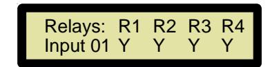
In this program mode, both Local and External Inputs are assigned to a combination of output relays K1-K4. When a Local or External Input Alarm is selected, the configured relays will stay energized as long as the alarm input is active. This is useful for driving other industrial or control signals during tone and voice activation from the panel.
1. In the "Relays: R1 R2 R3 R4" program mode, press the button to deactivate the current relay R1 selection for Input 1.
NOTE: "N" - the relay WILL NOT activate upon alarm or trouble conditions on the displayed input
"Y" - the relay WILL activate upon alarm or trouble conditions on the displayed input
2. Press to advance to the next available relay. Repeat step 1.
NOTE: Press to return to the previously programmed relay.
- 3. Repeat steps 1 and 2 to finish relay output assignment on Relays R3 and R4 on Input 1.
- 4. Press to advance to the next alarm input, Input 2.
- 5. Repeat steps 1 4 for each of the 4 local inputs as required.
- 6. Pressing after activation/deactivation of Relay 4 on Local Input 4 will advance to "Device Commission" setup. See Section 3.4.
3.4 - Device Commission
Device Commission allows for manual entry of serial devices located on the RS-485 data network. Once the device map is configured, devices will be continuously polled for their activity status. Devices not responding to a POLL command from the Master Panel, or devices reporting supervisory trouble can be viewed from the Trouble View on the front panel.
When the panel is in Master mode, the setup screen allows manual assignment and entry of serial devices into the device map and is used for future polling and zoning of devices on the RS-485 communications network.
IMPORTANT: This should only be done when devices are being commissioned for the very first time or devices are removed or added to the network. When a serial device is commissioned on the RS-485 network, it is assigned a unique physical address ranging from 00-3F Hex (64 decimal addresses). No two devices should be assigned the same address .
1. From the Master LCD screen, press full until LCD displays:
Device Commission Device: 00 Erased
NOTE: Device commission is only for use on the Master panel. If Satellite panels are connected to the Master panel, all devices on the satellite panel are non-addressable.
1. For each serial device on the network, press to display the device address. Once that device is displayed, press to store the device (or if the device has been removed from the network, press to change it to "Erased.")
NOTE: Pressing the button at any time will jump back to the previous serial device address.
NOTE: A device that is "Stored" will be polled by the Millennium System Master. A device that has been "Erased" is NO
longer active in the device map and will not be addressed during supervisory polling from the panel.
NOTE: "Stored" devices can also support zoning functions during panel output activity.
3.5 - Dynamic Zone Control™
When the panel is in Master mode, the Dynamic Zone Control (DZC™) program setup provides zone assigned for each of the serial devices "Stored" in the device map (See Section 3.4). The panel supports up to four zones but only one zone can be assigned to each serial device.
The zone assignment assigns a zone to each serial device. If the zone is not set, it will automatically default to Zone A.
NOTE: Non-serial devices connected to the Millennium System Master will be activated with any zone activation.
1. From the Master LCD screen, press ruc until LCD displays:
Device Zone Assign Device: 00 Zone: A
- 2. Press to change the displayed device to the desired zone (A D).
- 3. Press to advance to the next available serial device configured in the device map.
- Repeat steps 2 and 3 until all serial devices have been assigned a zone.
NOTE: Serial devices not manually assigned zones will default to Zone A.
NOTE: In order for a device to receive a new Dynamic Zone Control assignment, the panel must complete one successful poll to the unit. Please allow approximately 1 minute for poll completion prior to testing and verification of zones.
3.6 - Communications Setup
Communications Setup allows for setup of the baud rate. Supported baud rates are: 1200, 2400, 9600, 19200. Default is 9600 BPS. Parity, data and stop bits are not programmable and are restricted to No Parity, 8 data bits and 1 stop bit.
NOTE: Before setting the panel baud rate, be sure to properly configure remote devices to the same baud rate as the panel baud rate. This will avoid a trouble alarm associated with communication failures on remote serial devices. Refer to instructions supplied with remote devices for settings.
1. From the LCD screen, press Func until LCD displays:
Communications Setup BAUD: 9600,N,8,1
2. Press to advance to the desired baud rate.
3.7 - Panel Address Assignment
The panel address assignment is used only when the panel is in Satellite mode. Each satellite panel must be assigned a unique station address. The valid address range is 00-3F.
CAUTION
To avoid a communication failure, do not assign an address that has been assigned to another serial device on the network. See Section 3.4.
1. From either the LCD screen, press runc until LCD displays:
Set Panel Address Address: 00
- 2. Press the button to advance to the next available address. The valid address range is 00-3F.
- 3. Press the button to return to the previous address selection.
3.8 - Panel Mode
The panel must be configured as either a Master or Satellite panel. Panels configured as Master will initiate poll requests, assign dynamic zones and communicate to serial devices. Panels configured as Satellite will only reply to poll/status requests and accept dynamic zone commands from the Master Panel.
1. From the LCD screen, press the Func button until LCD displays:
Panel Mode Mode: MASTER
2. Press the button to select the desired mode of operation.
NOTE: When changing from "Satellite" to "Master" mode, be sure that previously "Stored" devices in the device map have been configured properly for baud rate (Section 3.6) and device commission selection (Section 3.4). This will eliminate any possible communication trouble conditions encountered once the panel resumes the polling sequence.
3.9 - Auto Learn Mode
The Auto Learn Mode allows for automatic entry and storage of serial devices into the device map. During this program setup, the panel will detect active devices on its RS-485 network and build a device map based on the active devices found. The device map is then stored in the panel's non-volatile memory indefinitely. As new serial devices are added or removed from the network, this utility should be run for updating the device map.
1. From the LCD screen, press the Func button until LCD displays:
AUTO LEARN MODE <chg> - Yes, <func> - No
Press the button to begin auto learn mode detection.
NOTE: If you do not want to use the auto learn mode, pressing will advance to the next setup screen.
PAGE 17 P/N 3100471 ISSUE 3
When the button is pressed, the panel will begin to poll all unit addresses beginning at address 00 and ending at address 3F. As devices are found, they are stored in the panel's device map. The program setup will run two times for redundancy and reliability. Once complete, the LCD screen with display:
AUTO LEARN COMPLETE <func> - continued
Press Func button to advance to the next setup screen.
After running the Auto Learn mode, devices detected and stored in the device map should be verified by the user in the Device Commission program setup (See Section 3.4). Each configured device can be viewed.
When devices are first stored in the device map, they are assigned Dynamic Zone A. Dynamic zones for the individual devices can be changed in the Device Zone Assignment Program Setup (See Section 3.5).
NOTE: In order for a device to receive a new Dynamic Zone assignment, the panel must complete one successful poll to the serial unit. Please allow approximately 1 minute for poll completion prior to testing and verification of zones.
Only Master panels support Dynamic Zones.
3.10 - Zone to Input Assignment
Each serial device on the panel's RS-485 network can be assigned a specific dynamic zone from A through D. Dynamic zone assigned for each device configured in the device map is stored in non-volatile memory. Each time a serial device is polled, its stored Dynamic Zone assignment command is sent out. When system audio is initiated from the Master panel, those devices with matching Dynamic Zones will broadcast the Master panel's system audio; all other serial devices will be prohibited from the current audio broadcast.
NOTE: Non-serial devices connected to the Master panel will broadcast system audio for any and all zones.
From the LCD screen, press the putton until LCD displays "Zones: A B C D" as shown below. From this mode, both local and external alarm inputs can be assigned to a combination of zones (up to 4 zones maximum for each alarm input)
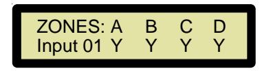
To activate or deactive the current Zone for Alarm Input 1, press the button. More than one zone can be active for each input.
NOTE: "N" - the zone WILL NOT broadcast when the input is active "Y" - the zone WILL broadcast when the input is active
3. Press to advance to the next zone. Repeat step 2.
NOTE: Press to return to the previously programmed relay.
- 4. Repeat steps 2 and 3 to finish zone to input assignment on Input 1.
- 5. Press to advance to the next alarm input, Input 2.
- 6. Repeat steps 2 5 for each of the 4 local inputs as required.
Pressing after activation/deactivation of Zone D on Input 4 will advance to "Voice Message Setup" menu. See Section 3.11.
3.11 - Voice Message Setup
The panel features voice messaging capability. This program setup allows the user to easily record and store voice messages in four separate message locations. Voice messages can then be selected and assigned to Local Alarm Inputs in the "Local Inputs" Assignment program setup screen.
CAUTION
The panel supervision must detect recorded audio in each location or the panel will receive a trouble indication.
From the LCD screen, press the button until LCD displays:
Voice Message Setup Location: 01 REC-OFF
This mode allows recording and storage of voice messages for later playback. The panel supports up to four five-second voice messages. Message lengths greater than five seconds are possible by extending the recording length.
Note: Voice messages that become longer than five seconds will physically require two or more message locations. For example, a 20-second message would occupy all four message locations limiting the user to only ONE message. If a 20-second message is desired, record only in the first message location (tone 17) and assign this location to any four of the Local Alarm Inputs for playback. If other locations are assigned for playback, the message may be partial or incomplete. For a 15-second message, record in the second message location (tone 18); for a 10-second message, record in the third message location (tone 19). Any of these messages can be assigned to any of the Local Alarm Inputs.
To record a message:
- 1. Press the microphone's press-to-talk (PTT) button and speak clearly into the microphone. When finished recording, release the PTT button.
- To advance to the next voice message location, press the button.
- 3. Repeat steps 1 and 2 until all desired messages have been recorded.
NOTE: To play back the message(s) that you have recorded, cancel out of programming mode (by pressing) and activate the local input with the voice message programmed on it. If the voice message does not play, ensure that the input is programmed to play the recorded message. See Section 3.2 and Table 1.
3.12 - Standby Power Mode
The panel can be programmed to accept standby power from an Edwards EBPS10 auxiliary power supply or other UL regulated standby power source listed for fire. When this feature is enabled, the standby power input is continuously monitored for integrity. When disabled, the standby power input is only monitored when the panel has detected the loss of AC main power.
NOTE: When the System Master is used with a fire alarm panel, Standby Power MUST be installed and enabled.
From the LCD screen, press the button until LCD displays:
Standby Power Mode Mode: DISABLED
2. Press the button to enable/disable the standby power mode.
3.13 - Remote Programming
Millennium System Master panels can be programmed remotely using Edwards System Master programmer P/N XXXXXX. Enabling program mode to 'ready' begins to upload and download the sequence to the programmer. Once programming is complete, mode will change back to disabled.
Remote Programming MODE: Disabled Remote Programming MODE: Ready
The panel will be inoperative until the program sequence is completed and the panel has timed out of setup mode.
3.14 - Text Output String
Millennium System Master Panel is capable of interfacing to Edwards Message Center signs. Key inputs 1-4 can be programmed to recall message sign file labels A-Z. Up to two file labels can be assigned to each of the four key inputs. Each input can also address individual signs between addresses 00 and FF.
Text Output String Format is as follows:
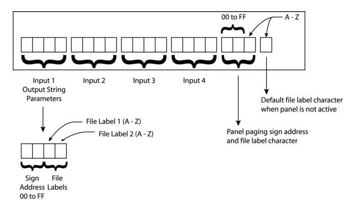
Example: Text Output String
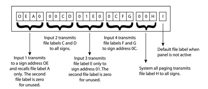
NOTES: Sign address 00 transmits to all signs on the network. Any unused file labels should be programmed with a zero "0" in the file label location as shown in the example above.
3.15 - Security
The panel programming can be secured after programming is complete. Using the keys supplied with the console, turn the lock on the inside door (below the LCD panel) until it stops. In this position, all alarm and paging inputs can be activated but the function key is disabled.
PAGE 19 P/N 3100471 ISSUE 3
Table 1. Tone Programming
| Tone | Description | HEX |
|---|---|---|
| Ding-Dong | Percussive pairs of 700 and 570 Hz tones, each damped to zero | 01 |
| Warble | 575 and 770 Hz alternately, 87 ms each | 02 |
| Siren | 600-1250 Hz up and down sweep in 8 seconds and repeat | 03 |
| Stutter | Percussive 470 Hz, 83 ms on, 109 ms off | 04 |
| Slow Whoop | 600-1250 Hz upward sweep in 4 seconds and repeat | 05 |
| Beep | 470 Hz, 0.55 seconds on, 0.55 seconds off | 06 |
| Chime 1 | 700 Hz percussive repeat at 1 Hz | 07 |
| Fast Whoop | 600-1250 Hz upward sweep in 1 second and repeat | 08 |
| Hi/Lo | 780 to 600 Hz alternately, 0.52 seconds each | 09 |
| Rapid Siren | 600-1250 Hz up and down sweep in 0.25 seconds and repeat | 0A |
| Yeow | 1250-600 Hz downward sweep in 1.6 seconds and repeat | 0B |
| Horn | 470 Hz continuous | 0C |
| Air Horn | 370 Hz continuous | 0D |
| Dual Tone | 450-500 Hz, 0.4 to 0.5 second cycle | 0E |
| Chime 2 | 575 Hz percussive repeat at 1 Hz | 0F |
| Westminster | Two measures, 411 Hz, 520 Hz, 407 Hz, 312 Hz | 10 |
| Three Blind Mice | Four measures, 787 Hz, 714 Hz, 625 Hz, 952 Hz, 333 Hz | 11 |
|
Phasor
Telephone |
416-625 Hz up and down sweep in 13 ms and repeat
570 and 770 Hz alternately, 50 ms each for 1.2s, 1.5s delay and repeat |
12
13 |
| Staircase | 440-2000 Hz up and down steps, 750 ms delay and repeat | 14 |
| 3 Tone Alert | 463, 641 and 896 Hz, 200 ms each, 1 second delay and repeat | 15 |
| Presignal Chime | 470 Hz percussive repeat at 1.5 Hz, followed by Message 1 | 16 |
| Message 1 | Field recorded voice message | 17 |
| Message 2 | Field recorded voice message | 18 |
| Message 3 | Field recorded voice message | 19 |
| Message 4 | Field recorded voice message | 1A |
| NFPA Whoop | Three 422-775 Hz upward sweeps, 850 ms each, 1s delay and repeat | 1B |
| 3 Pulse Horn | 470 Hz, 3 0.5 second pulses separated by 0.5 seconds followed by a 1.5 second delay and repeatFor Evacuation Use Only | 1C |
| 3 Pulse Air Horn | 370 Hz, 3 0.5 second pulses separated by 0.5 seconds followed by a 1.5 second delay and repeatFor Evacuation Use Only | 1D |
| 3 Pulse Dual Tone | 450-500 Hz, 0.4 to 0.5 second cycle, 3 0.5 second pulses separated by 0.5 seconds followed by a 1.5 second delay and repeatFor Evacuation Use Only | 1E |
| 3 Pulse Chime 2 | 575 Hz, 3 0.5 second pulses separated by 0.5 seconds followed by a 1.5 second delay and repeatFor Evacuation Use Only | 1F |
| European Police | 969 Hz and 800 Hz alternately 0.250 seconds each | 20 |
| European Fire | 982 Hz and 864 Hz downward sweep in 0.134 seconds | 21 |
| European Slow Whoop | 658 Hz to 1312 Hz upward sweep in 3 seconds followed by 0.5 second delay and repeat | 22 |
| European General | 1087 Hz for 0.5 seconds followed by 0.5 second delay and repeat | 23 |
| European Toxic | 982 Hz continuous | 24 |
| European Police 2 | 554 Hz and 440 Hz alternately 0.800 seconds each | 25 |
| European Stutter | 3876 Hz for 0.146 seconds followed by 0.102 seconds delay and repeat | 26 |
| European Sweep | 1315 Hz to 413 Hz downward sweep in 1.17 seconds and repeat | 27 |
| Telephone 2 | Alternate tones at 567 Hz and 326 Hz, for 0.052 seconds each | 28 |
| Buzzer 1 | 1315 Hz and 746 Hz alternating for 0.003 seconds each | 29 |
| Genesis Horn Cont. | Continuous Genesis horn | 2A |
| Genesis Horn Temp. | Temporal Genesis horn | 2B |
| Warning 1 | 1207 Hz and 493 Hz, alternately 0.002 seconds each | 2C |
| Warning 2 | 2336 Hz and 493 Hz, alternately 0.005 seconds each | 2D |
| Warning 2 Beep | 0.500 second of 2336 Hz and 493 Hz, each alternating for 0.005 seconds, followed by 1 second delay | 2E |
| Caution | 453 Hz for 0.040s, 235 Hz for 0.020s, 235 Hz for 0.160s, 260 Hz for 0.050s, 260 Hz for 0.1009s, 235 Hz for 0.050s | 2F |
| Multi-Tone | 376, 357, 352, 382, 355, 375, 384, 375 and 364 Hz alternately on for 0.050 seconds | 30 |
| Attention | 2232, 4545, 3704, 2777, 4347, 3704, 2500 Hz alternately on for 0.003 seconds | 31 |
| High Freq. StdyAlert | 2500 Hz continuous | 32 |
| High Freq. Fast Siren | 2500 to 3048 Hz up and down sweep in 0.130 seconds | 33 |
| High Freq. Slow Siren | 2500 to 3048 Hz up and down sweep in 0.500 seconds | 34 |
| DIN PFEER | Ramp downward from 1336 Hz to 522 Hz in 1.2 seconds and repeat | 35 |
| NFS 32 001 | 584 Hz for 0.100 seconds and 461 Hz for 0.400 seconds | 36 |
| Ode to Joy | 6.45 seconds of melody followed by 1 second delay and repeat | 37 |
| Twinkle Little Star | 13.2 seconds of melody followed by 1 second delay and repeat | 38 |
| Dueling Banjos | 10.84 seconds of melody followed by 1 second delay and repeat | 39 |
| La Cucaracha | 7.10 seconds of melody followed by 1 second delay and repeat | 3A |
| Yellow Rose of Texas | 19.34 seconds of melody followed by 1 second delay and repeat | 3B |
| Presignal Message 2 | 470 Hz percussive repeat at 1.5 Hz, followed by Message 2 | 3C |
| Presignal Message 3 | 470 Hz percussive repeat at 1.5 Hz, followed by Message 3 | 3D |
| Presignal Message 4 | 470 Hz percussive repeat at 1.5 Hz, followed by Message 4 | 3E |
| Non Repeating Voice Msg 1 | Non Repeating Field Recorded Voice Message | 3F |
| Non Repeating Voice Msg 2 | Non Repeating Field Recorded Voice Message | 40 |
| Non Repeating Voice Msg 3 | Non Repeating Field Recorded Voice Message | 41 |
Chapter 4 - Maintenance
4.1 - Preventive Maintenance
Before commencing testing, notify all areas where the alarm sounds and off-premises locations that receive alarm and trouble transmissions that testing is in progress.
- Records of all testing and maintenance shall be kept as required by the authority having jurisdiction.
-
· Required tools:
- Slotted or Phillip style #2 screwdriver, insulated
- Alligator style jumper clips (12 inch lead length)
- Digital multi-meter
- Front panel door key
- Program mode security key
- Sound level meter
- A complete check of installed field wiring and devices should be made at regular intervals in accordance with NFPA 72 requirements. This includes testing all alarm and supervisory initiating devices and circuits and any off-premises connections.
- Panel operation should be verified in the alarm, supervisory and trouble modes.
- To ensure that the panel can be powered when primary power is lost, standby power to the panel should be periodically inspected, tested, and replaced (at a minimum) every four years.
4.2 - Preventive Maintenance Schedule
Refer to NFPA 72, Chapter 7, Inspection, Testing and Maintenance for more information on required inspection and testing methods and frequency of fire alarm systems and devices. For detector sensitivity and functionality testing, refer to the detector manufacturer's installation instructions.
PAGE 21 P/N 3100471 ISSUE 3
Chapter 5 - LCD Messages and Troubleshooting
5.1 - Normal Mode
When in normal mode, the following messages will be displayed on the LCD screen of the Millennium System Master. It should be noted that the zones shown below will not appear if the panel is in satellite mode.
Display Illuminated LED's Description
None Displayed when the panel is in Standby mode. If panel is set for Master, bottom line will be as shown. If panel is set as Satellite, bottom line on LCD display will read "SATELLITE MODE." Panel is performing supervision while this message is being displayed.
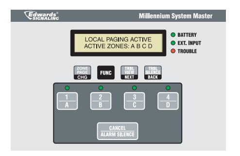
None Displayed when the panel microphone push to talk (PTT) button is depressed. Message will return to normal upon release.
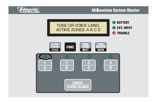
Input LED (1, 2, 3, or 4) When alarm is activated using local based on input key selected inputs 1, 2, 3 or 4 on the keypad, the display will show "TONE OR VOICE LABEL." Message will return to standby message when cancel/alarm silence key is pressed.
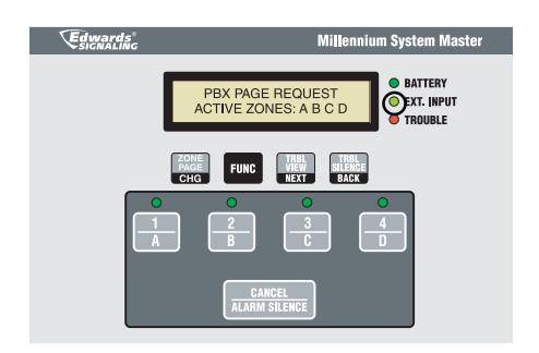
External Input Displayed when the telephone access input is activated via contact closure from the UL Listed telephone access module interface. Message will return to standby message upon contact release.
Display
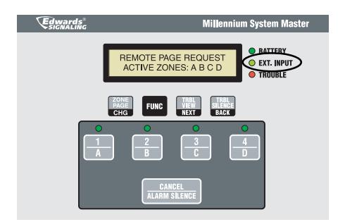
Illuminated LED's
External Input
Description
Displayed while a message is being sent via a 5542RPU microphone. Message will return to standby message once the RPU request line is inMactive.
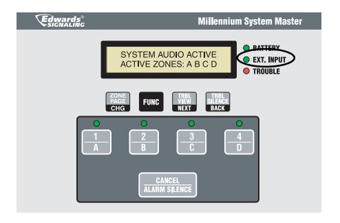
External Input on Satellite panel
Displayed with the panel is in Satellite Mode and a serial system audio command is received, along with the zone qualifier, the panel will switch on and pass sytem audio through to its conventional system amplifiers. Message will return to standby message when either a serial system audio disable command is received or if the user presses the cancel/alarm silence key.
5.2 - Troubleshooting and Trouble Messages
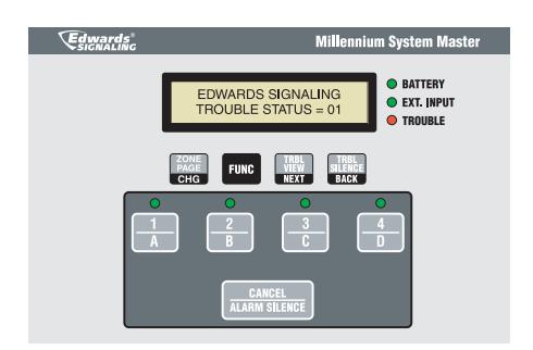
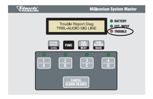
When in trouble mode, the following messages will be displayed on the LCD screen of the Millennium System Master. When a trouble indication is received, the trouble LED will illuminate and the display will read as shown below. The number after "TROUBLE STATUS" indicates the number of troubles the panel has received. To view the trouble, press the button. If more than one trouble status exists, you can press the button again to see each of the remaining indications. The following information will describe the trouble indications, what they mean and possible solutions to the problem.
Display
Illuminated LED's
Trouble
Description
Wiring is faulty on MAIN OUT terminals. The panel is not able to detect the end-of-line resistor on the line. Ensure that end-of-line resistor is properly connected and wiring loop is not broken or shorted.
PAGE 23 P/N 3100471 ISSUE 3
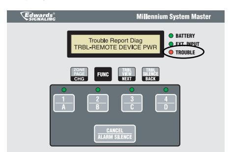
Display Illuminated LED's Description
Trouble The panel has detected a missing end-ofline resistor, trouble with wiring (break in wiring or fault wiring), or a speaker/ amplifier has lost power.
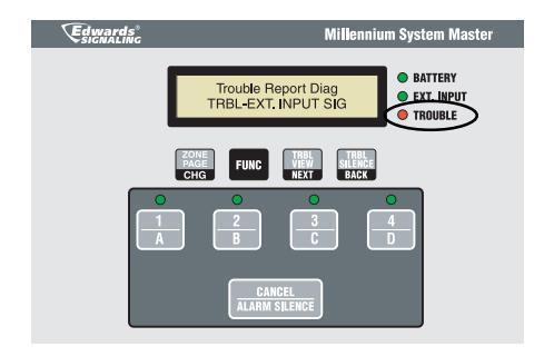
Trouble The panel has detected bad wiring or a faulty or missing end-of-line resistor on one of the external input contacts.
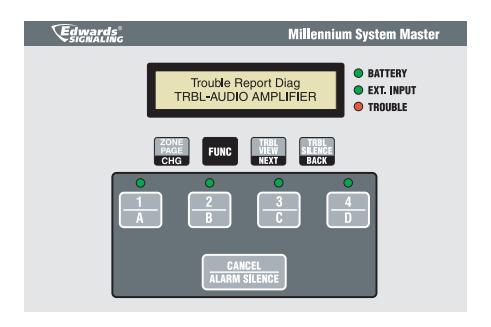
Trouble The amplifier or associated circuitry is faulty, MAIN OUT volume adjustment is set below 2.5V RMS.
To increase MAIN OUT volume, turn the potentiometer located on the main PC board clockwise. Press the button to silence the trouble see if the trouble has been cleared.
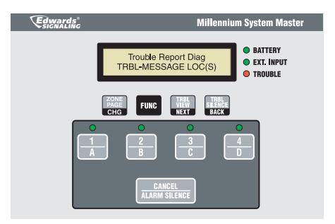
Trouble (1) or more message locations are empty or the associated circuitry is faulty.
Message locations can be checked by pressing the input button that the message location is associated with. If the message location is not being used, it can be temporarily assigned to an input contact. See Chapter 3 - Programming.
NOTE: In the case of voice message failure, the System Master will automatically generate a 3 Pulse evacuation tone within 30 seconds of an evacuation alarm activation. All four LEDs associated with the input keys will be illuminated during this activation.
Trouble Indication caused by a decrease of the battery backup voltage to less than 19V. Check to see that the battery backup is connected properly and that the batteries are properly charged.
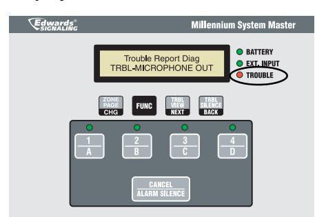
Display Illuminated LED's Description
Trouble Indication occurs when the microphone is missing or wiring is faulty.
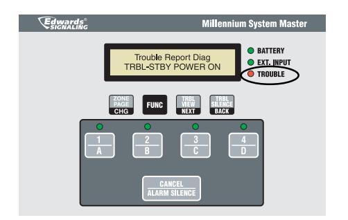
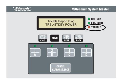
Trouble When Standby Power Mode is enabled and AC power is lost, this indicates that the panel is running on battery backup
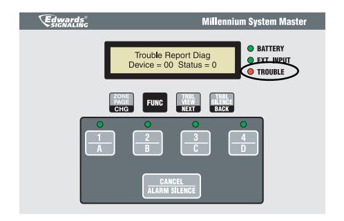
Trouble Panel has lost communication with serial device indicated.
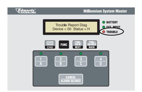
Trouble Satellite panel assigned to this device address is reporting a trouble condition on one or more functions. To see the trouble indications, you must use the TRBL VIEW on the satellite panel.
Appendix A - Calculations
Battery calculation worksheet
Use this worksheet to determine the minimum amperage capacity required for the panel's standby power source. You can obtain operating current requirements for amplifier units from their respective installation sheets. For 5532M series amplifiers, the audio signal draw for each audio amplifier is approximately 2 mA at 470 Hz.
NOTE:
Base panel includes the main controller board with no system audio output loading and only EOL resistors.
Standby current: Master and Satellite - 230 mA
Alarm current: Master and Satellite - 215 mA
NOTE:
Alarm current with no amplifier loading is less because EOL resistor path is opened during alarm condition and closed
during supervision.
|
Standby
Current (mA) |
Alarm
Current (mA) |
||
|---|---|---|---|
| Base Millennium System Master Panel [1] | |||
|
RPU Current draw
(See Form A) |
|||
|
Audio Amplifier Loading
(See Form B) |
0 | ||
| Total Current | |||
| Required standby and alarm time | Standby time 24 or 60 hour |
Alarm time 5 min = 0.083
10 min = 0.167 15 min = 0.250 30 min = 0.500 |
|
| mAh | + mAh = mAh | ||
| /1000 | |||
| Battery amp hour total = Ah | |||
| x 1.2 | |||
| + 0.25 | |||
| Minimum battery size [2] = Ah |
Form A
| Product | Quantity |
Standby
current (mA) |
Qty x Standby
current (mA) |
Paging
current |
Qty x Paging
current (mA) |
|---|---|---|---|---|---|
| 5542RPU | 5 | 22 | |||
|
Total RPU
Current [2] |
[1] See Appendix C for the maximum number of amplifiers supported by the panel.
[2] RPU power supplied by panel cannot exceed 0.55A (paging current). If more than 0.55A is required, you must reduce number of RPU devices supplied by the panel.
Form B
|
Audio
Amplifier |
Quantity of
Audio Amplifiers [1] |
Individual
Amplifier Current Draw (mA) |
Total Current Draw (quantity x Amplifier current in mA) |
|---|---|---|---|
| 5532M | |||
| Total current draw for all amplifiers = |
[1] See Appendix C for the maximum number of amplifiers supported by the panel.
5532M Audio Amplifier Voltage Drop Calculation
| Circuit length (single conductor) | Total Circuit current to unit |
Wire resistance
per 1000 ft [1] |
Voltage
drop |
|||
|---|---|---|---|---|---|---|
| feet | x 2 x | Amps | Х | ohms | /1000 = | |
| Audio output from panel or previous unit's End of line circuit | Voltage drop | End of line voltage [3] | Voltage drop | ||||
|---|---|---|---|---|---|---|---|
| - | _ | / |
| Voltage drop | Audio output from panel or previous unit's end of line circuit [2] |
Voltage
drop % |
||
|---|---|---|---|---|
| / | = | |||
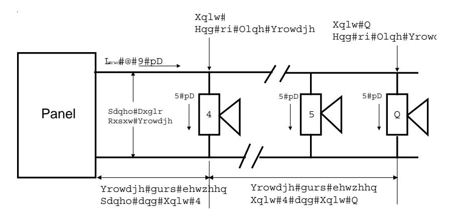
Example -- Determine voltage drop from Panel to Unit 2
Steps
- 1. Obtain single conductor wire legnth from Panel to Unit 2.
- 2. Obtain total circuit current from Panel's audio output
- 3. Using wire type from below and table from above, calculate voltage drop to Unit 2.
- 4. Unit 2 End of Line Voltage = Panel Audio Output or Previous Unit s End of Line Voltage Unit 2 Voltage Drop
Notes
- [1] Use 1.6 for 12 AWG and 2.5 sq mm wire, 2.6 for 14 AWG and 1.5 sq mm wire, 4.2 for 16 AWG and 1.0 sq mm wire and 6.6 for 18 AWG and 0.75 sq mm wire
- [2] Panel audio output voltage is 10.6V
- [3] In order to produce a minimum 75 d output, voltage should not be less than 9
PAGE 27 P/N 3100471 ISSUE 3
5532M Amplifier Circuit Maximum Wire Length Calculation
Use this worksheet to determine the maximum wire length of an Audio Amplifier appliance circuit. Fill in one worksheet for each Audio Amplifier appliance circuit connected to the panel.
Wire length matrix
Wire lengths in the following table are based on a voltage drop of 1.6 volts or 15% of the Panel's audio output End of line appliance.
| Current | ! | Maximum wire length (ft) | ||||||||
|---|---|---|---|---|---|---|---|---|---|---|
| required (A) | 18 AWG | 16 AWG | 14 AWG | 12 AWG | ||||||
| 0.25 | 584 | 950 | 1460 | 2170 | ||||||
| 0.50 | 292 | 474 | 730 | 1084 | ||||||
| 0.75 | 194 | 316 | 486 | 722 | ||||||
| 1.00 | 146 | 236 | 364 | 542 | ||||||
| 1.25 | 116 | 190 | 292 | 434 | ||||||
| 1.50 | 92 | 158 | 242 | 362 | ||||||
| Maximum signal loss allowed [1] | V | |
|---|---|---|
| x _ | 1000 | |
| Wire resistance per 1000 ft/pair x 2 [2] | ||
| (2x the number in note 2) | /_ | ohms |
| ohms | ||
| Total operating current required | / | A |
| Maximum wire length | ft |
Notes
- [1] 1.6V<sub>ms</sub> loss in order to produce 75 dBA minimum. [2] Use 1.6 for 12 AWG and 2.5 sq mm wire, 2.6 for 14 AWG and 1.5 sq mm wire, 4.2 for 16 AWG and 1.0 sq mm wire and 6.6 for 18 AWG and 0.75 sq mm wire
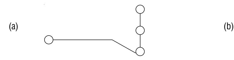
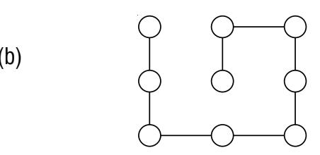
Suggested Network Topology Node Schemes

PAGE 29 P/N 3100471 ISSUE 3
Appendix B - Programming Template
| (1) Project Name | Project Address | |||||
|---|---|---|---|---|---|---|
| Programmed by | Date | Tested by | Date | |||
| (2) Local Input Assignment | (9) Device Map and Dynamic Zone Assignment | |||||
| Input 1 - Tone # | Device | |||||
| Input 2 - Tone # | ||||||
| Input 3 - Tone # | (Circle one only) | |||||
| Input 4 - Tone # | 00 |
A
B C D |
||||
| 01 |
A
B C D |
|||||
| (3) Output Relay Assignment | 02 |
A
B C D |
||||
| Relays | R1 | R2 | R3 | R4 | 03 |
A
B C D |
|
Y
N |
Y
N |
Y
N |
Y
N |
04 |
A
B C D |
|
| Input 1 | 05 |
A
B C D |
||||
| Input 2 | 06 |
A
B C D |
||||
| Input 3 | 07 |
A
B C D |
||||
| Input 4 | 08 |
A
B C D |
||||
| 09 |
A
B C D |
|||||
| (4) Alarm Input to Zone Assignment | 0A |
A
B C D |
||||
| Zones | ZA | ZB | ZC | ZD | 0B |
A
B C D |
|
Y
N |
Y
N |
Y
N |
Y
N |
0C |
A
B C D |
|
| Input 1 | 0D |
A
B C D |
||||
| Input 2 | 0E |
A
B C D |
||||
| Input 3 | 0F |
A
B C D |
||||
| Input 4 | 10 |
A
B C D |
||||
| 11 |
A
B C D |
|||||
| (5) Communications Setup | 12 |
A
B C D |
||||
| Baud Rate | 1200 | 2400 | 9600 | 19200 | 13 |
A
B C D |
| 14 |
A
B C D |
|||||
| (6) Satellite Panel Address | 15 |
A
B C D |
||||
| Satellite Unit Name | Address | 16 |
A
B C D |
|||
| 17 |
A
B C D |
|||||
| (7) Panel Mode | 18 |
A
B C D |
||||
| Mode | Master | Satellite | 19 |
A
B C D |
||
| (8) Standby Power Mode | 1A |
A
B C D |
||||
Mode Enabled Disabled
| (9) Device Map and Dynamic Zone Assignment | ||||||
|
Device
Address Description |
Zone | Erased | Stored | |||
| (Circle one only) | ||||||
| 00 | A | B | C | D | ||
| 01 | A | B | C | D | ||
| 02 | A | B | C | D | ||
| 03 | A | B | C | D | ||
| 04 | A | B | C | D | ||
| 05 | A | B | C | D | ||
| 06 | A | B | C | D | ||
| 07 | A | B | C | D | ||
| 08 | A | B | C | D | ||
| 09 | A | B | C | D | ||
| 0A | A | B | C | D | ||
| 0B | A | B | C | D | ||
| 0C | A | B | C | D | ||
| 0D | A | B | C | D | ||
| 0E | A | B | C | D | ||
| 0F | A | B | C | D | ||
| 10 | A | B | C | D | ||
| 11 | A | B | C | D | ||
| 12 | A | B | C | D | ||
| 13 | A | B | C | D | ||
| 14 | A | B | C | D | ||
| 15 | A | B | C | D | ||
| 16 | A | B | C | D | ||
| 17 | A | B | C | D | ||
| 18 | A | B | C | D | ||
| 19 | A | B | C | D | ||
| 1A | A | B | C | D | ||
| 1B | A | B | C | D | ||
| 1C | A | B | C | D | ||
| 1D | A | B | C | D | ||
| 1E | A | B | C | D | ||
| 1F | A | B | C | D |
Appendix B - Programming Template (Cont'd)
| (1) Project Name | Project Address | ||
|---|---|---|---|
| Programmed by | Date | Tested by | Date |
| (9) Device Map and Dynamic Zone Assignment (Cont'd) | |||||
|
Device
Address Description |
Zone | Erased | Stored | ||
| (Circle one only) | |||||
| 20 |
A
B |
C
D |
|||
| 21 |
A
B |
C
D |
|||
| 22 |
A
B |
C
D |
|||
| 23 |
A
B |
C
D |
|||
| 24 |
A
B |
C
D |
|||
| 25 |
A
B |
C
D |
|||
| 26 |
A
B |
C
D |
|||
| 27 |
A
B |
C
D |
|||
| 28 |
A
B |
C
D |
|||
| 29 |
A
B |
C
D |
|||
| 2A |
A
B |
C
D |
|||
| 2B |
A
B |
C
D |
|||
| 2C |
A
B |
C
D |
|||
| 2D |
A
B |
C
D |
|||
| 2E |
A
B |
C
D |
|||
| 2F |
A
B |
C
D |
|||
| 30 |
A
B |
C
D |
|||
| 31 |
A
B |
C
D |
|||
| 32 |
A
B |
C
D |
|||
| 33 |
A
B |
C
D |
|||
| 34 |
A
B |
C
D |
|||
| 35 |
A
B |
C
D |
|||
| 36 |
A
B |
C
D |
|||
| 37 |
A
B |
C
D |
|||
| 38 |
A
B |
C
D |
|||
| 39 |
A
B |
C
D |
|||
| 3A |
A
B |
C
D |
|||
| 3B |
A
B |
C
D |
|||
| 3C |
A
B |
C
D |
|||
| 3D |
A
B |
C
D |
|||
| 3E |
A
B |
C
D |
|||
| 3F |
A
B |
C
D |
|||
PAGE 31 P/N 3100471 ISSUE 3
Appendix C - Panel Specifications
|
External Initiating
Device Circuits (EID) |
Contact Closure
Initiating Circuit |
4 total | ||
|---|---|---|---|---|
|
5532M Series Audio
Amplifier Circuits |
Class B, Style Y | 200 maximum | ||
|
Maximum System Audio Output to
5532M Amplifier units |
1.0 amp @ 10V RMS at ambient 25C | |||
| Standby Current | Alarm Current | |||
| AC input* | 120V AC 50/60 Hz | 0.14A | 0.37A | |
| 240V AC 50/60 Hz | 0.10A | 0.22A | ||
| Base panel DC current draw** | 230 mA | 215 mA | ||
| Battery standby voltage | 19 - 25.7V DC | |||
| +VS RPU supply current (max.) | 0.55A (used for Remote Paging Units) | |||
| +VS RPU output voltage |
+24V DC + 10% (main AC power present),
19 - 25.7V DC (battery standby) |
|||
| System Audio Output Circuit |
Maximum loop resistance: 26 ohms
Maximum loop capacitance: 440 µF |
|||
| External Initiating Device Circuit |
Maximum loop resistance: 13 ohms
Maximum loop capacitance: 15 µF |
|||
| Alarm and Trouble Output Contact |
Form C: 4A @ 30V DC (resistive load)
Form C: 5A @ 240V AC (general use) |
|||
| Environmental |
Temperature: 0 - 49C (32 - 120F)
Humidity: 5 - 93% relative humidity, non-condensing |
|||
| Terminal rating | All terminals rated for 12 to 18 AWG (0.75 to 2.5 sq mm) | |||
| Serial communications |
Style 4
Communication Circuit |
Asynchronous communications
Maximum resistance: 13 ohms Maximum capacitance: 0.03 µF |
||
* Full system load (except max. RPU loading)
** No load except EOL resistors on System Audio Out and External Initiating Input contacts
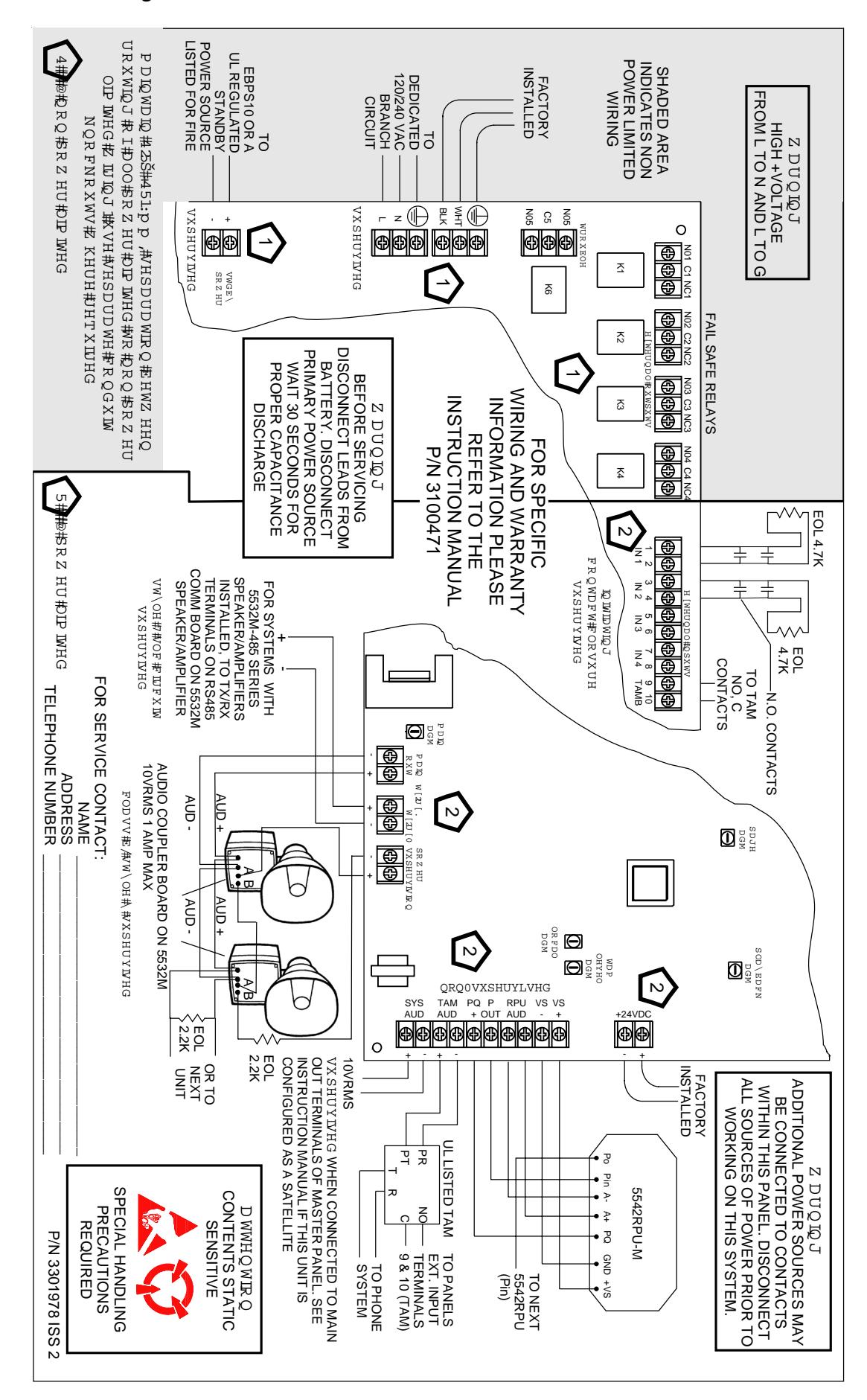
Appendix D - Wiring
PAGE 33 P/N 3100471 ISSUE 3