Edwards Signaling 5536M Series Installation Instructions
Open the original PDF document
View PDF

EDWARDS Installation Instructions for Catalog Series 5536M-24 and SIGNALING 5536MHV-24 Adaptatone® Millennium Local/System Signal
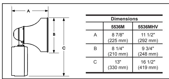
Figure 1. Dimensions
Description and Operation
Edwards Adaptatone is a heavy-duty, tone-selectable, stand alone, indoor/outdoor audible signaling device intended for industrial applications where high audible output and microcomputer reliability are required. Catalog Numbers ending with suffixes -24AQ or -24Y6 are CE Marked and TUV-RHEINLAND Certified for compliance to the European Union's Electromagnetic Compatibility (Industrial) and Low Voltage Safety Directives (see Declaration of Conformtiy, available upon request). Additionally, the Adaptatone Millennium series are UL and cUL Listed as Audible Signal Appliances for use in the following hazardous locations.
|
Catalog
Number |
Hazardous
Locations |
Temp.
Code |
|---|---|---|
| 5536M-24AQ | Class I, Div. 2, Groups A, B, C, D | T4 (135C) |
|
5536M-24N5
5536M-24Y6 5536MHV-24AQ 5536MHV-24Y6 |
Class II, Div. 2, Groups F, G
Class III, Div. 1 and 2 |
T5 (100C) |
The Adaptatone operates from local power and sounds a high decibel signal determined by the setting of miniature programming switches inside the unit. The Adaptatone may be programmed for any of the 27 tones listed in Figure 11.
Three tones may be programmed into the unit at any time. These tones operate on a pyramid-type priority system. The tone programmed on SW2 overrides the tones programmed on SW3 and SW4. The tone on SW3 overrides the tone programmed on SW4. An external audio signal up to 12V RMS can be connected to take priority over all internally generated tone signals.
The decibel output level and speaker lateral position are both easily adjustable.
Mechanical Specifications
| Weight | 9 Pounds (4.1 kg) |
|---|---|
| Hazardous Locations, UL S | |
| Ambient Temp | +41F to +104F (+5C to +40C) |
Non-Hazardous Locations Variable Ambient Temp. ..... -40F to +151F (-40C to +66C)
Hazardous Locations and Variable Ambient Conditions apply only where UL listings are accepted and do not apply to CE conformity or TUV-Rheinland Certification.
Electrical Specifications
| Input Board | Main Power | |||||
|---|---|---|---|---|---|---|
| Catalog | Curre | ent (A) | ||||
| Number | Voltage | Current | Voltage | Standby | Tone On | |
| Standard Volume | ||||||
| 5536M-24AQ | 24V DC | 6 mA |
24V DC
24V AC 50/60 Hz |
0.10
0.10 |
0.74
1.3 |
|
| 5536M-24N5 | 24V DC | 6 mA | A 120V AC 50/60 Hz 0.10 | 0.36 | ||
| 5536M-24Y6 | 24V DC | 6 mA |
125V DC*
250V DC* 120V AC 50/60 Hz 240V AC 50/60 Hz |
0.10
0.02 0.10 0.10 |
0.21
0.10 0.32 0.20 |
|
| High Volume | ||||||
| 5536MHV-24AQ | 24V DC | 6 mA |
24V DC
24V AC 50/60 Hz |
0.10
0.10 |
1.5
2.3 |
|
| 5536MHV-24Y6 | 24V DC | 6 mA |
125V DC*
250V DC* 120V AC 50/60 Hz 240V AC 50/60 Hz |
0.10
0.02 0.10 0.10 |
0.39
0.19 0.56 0.34 |
|
* CE mark and TÜV-Rheinland Certifications do not apply to 125V DC or 250V DC.
Installation
The Adaptatone may be mounted to any flat surface or may be used as a freestanding unit mounted to a rigid pipe. The Adaptatone must be installed in accordance with the latest edition of the National Electrical Code or other regulations applicable to the country and locality of installation and by a trained and qualified electrician.
NOTE: The increased resistance due to long wire runs needs to be accounted for in sizing wire. Consult Applications Engineering for details.
For catalog numbers ending in "AQ", 24V AC power must be transformer isolated from mains or line power.

WARNING
To prevent fire, shock and component damage, NO work, including circuit board removal, should be performed while the circuit is energized.
NOTE: Any kind of service or maintenance performed while unit is energized will void the warranty.
-
1. Mount Adaptatone as shown in Figure 2.
- a. Flat Surface Mounting . Secure unit to mounting surface using the (4) mounting holes in the mounting plate on the rear of the box. Use the #10 x 3" (76 mm) wood screws (furnished loose) or other hardware (not supplied) suitable for the mounting surface.
- b. Rigid Pipe Mounting . Loosen the (4) cover screws from the signal box and lift off signal box cover.
NOTE: Cover screws are captive. Do not remove from cover
Remove the center knockout in lower wall of box and mount box to a 1/2" (12.7 mm) conduit pipe using suitable connector.
Table 1. Programming Logic Controller (PLC) Compatibility: PLC output to meet following product input parameters. See Figure 10.
| Cat. No. |
Operating voltage
(Volts*) |
Max. off state
leakage current (mA) |
Continuous on current (mA) |
Surge (inrush/duration)
(Amps/milliseconds) |
|---|---|---|---|---|
| 5536M-24AQ | 24V DC only | 2 | 740 | 8/4 |
| 5536M-24N5 | 120V 60 Hz | 2 | 360 | 2.82/4 |
| 5536MHV-24AQ | 24V DC only | 2 | 1500 | 8/4 |
| Input Board Circuit | 24V DC | 2 | 6 |
2. Install wires through a knockout hole in the bottom of the box from a raceway that is, with its connections to the 1/2" (12.7 mm) conduit knockout hole, approved for the same degree of protection and enclosure type needed by the application. Use the provided plastic tie-wrap, on the barrier to the electronics, to separate incoming power leads from signal and tone initiating leads, per NEC (Figure 3).
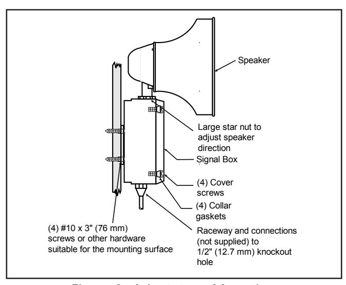
Figure 2. Adaptatone Mounting
A
WARNING
To prevent fire and shock, wire the Adaptatone only as described in this installation instruction.
-
3. Wire as follows:
- a. Connect green and yellow striped earth-ground wire to earth-ground.
- b. Select the appropriate method for wiring to the input board (Figure 9) from Figures 5 10. Connect the Adaptatone as shown.
- c. Connect incoming power to wire leads using a butt splice or other method listed, certified, or otherwise approved by local authorities. Leads are both black for -AQ and -N5 models and are black for line and white for neutral for -Y6 models.
- d. Optional. Connect external 24V DC battery (not supplied) in series with separate diode assembly part 2600010 (supplied) to TB1 terminals 3 and 4 on the main board as shown in Figure 4 and marked on the diode assembly.
NOTE: Terminal Block TB1 can be unplugged from the main board to complete wiring as shown in Figure 4.
Refer to Figures 9 and 11 and select desired tones. Set the miniature programming switches on the input board.
For input connected to IN2, set on SW2; IN3, set on SW3; IN4, set on SW4, in order of priority desired.
NOTE: Connection to IN1 is factory wired from Audio Input Board for the external audio signal and has priority over other signals when activated by the 24V DC priority signal (Figures 7 and 8).
A
WARNING
HIGH VOLTAGE is present when product is energized. High volume may cause harm to personnel in close proximity.
5. Adjust volume level, if desired, by turning potentiometer located on the main board (Figure 9).
A
WARNING
To ensure integrity of the Adaptatone assembly when adjusting the speaker direction, make sure threads in the enclosure remain fully engaged and do not turn speaker more than 360 degrees from the original factory installed position.
To adjust speaker direction, loosen large star nut (Figure 2) and turn speaker to the approximate desired position. Retighten nut and turn speaker slightly clockwise until locked into place.
A
WARNING
To ensure integrity of the enclosure: Ensure the cover gasket, part number P-007549-0069, is adhered into groove at cover perimeter before replacing the signal box cover
Ensure that the (4) collar gaskets, part number P-041930-0362, are in place on each cover screw before securing the signal box cover.
When securing cover, start screws by hand, making sure they are threaded into tapped holes in housing bosses before securing with a screwdriver. Torque signal box cover screws to a minimum of 20 in-lbs. This ensures the required tight fit.
- Tightly secure the signal box cover using (4) retained cover screws.
- 8. Torque signal box cover screws to a minimum of 20 in-lbs.
- 9. Verify operability.
P/N 3100009 ISSUE 2 Page 2
Maintenance and Test
WARNING To prevent fire, shock and component damage, NO work, including circuit board removal, should be performed while the circuit is energized. NOTE: Any kind of service or maintenance performed while unit is energized will void the warranty.
Examine the unit semi-annually for accumulation of dirt. Clean if necessary.
The Adaptatone should be tested annually or as required by the authority having jurisdiction to ensure continuous service.
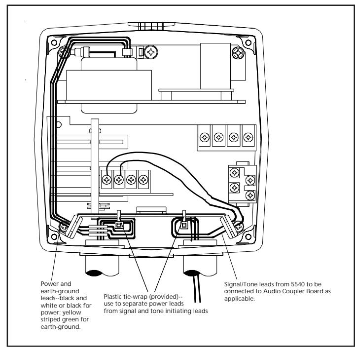
Figure 3. Wiring the Adaptatone
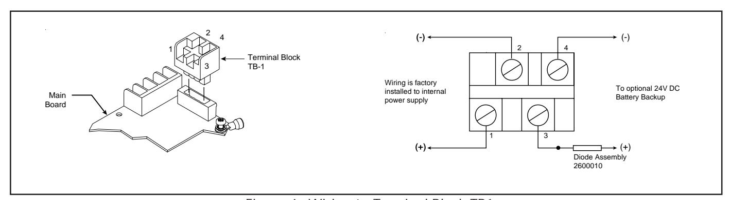
Figure 4. Wiring to Terminal Block TB1
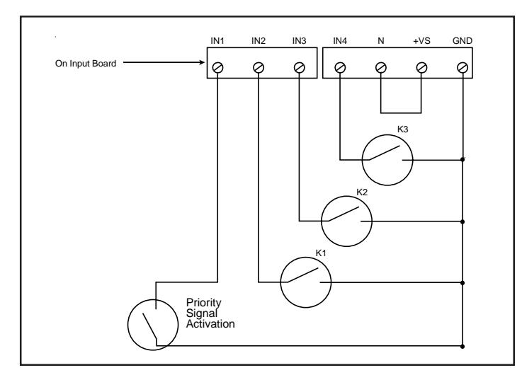
Figure 5. Installing with Multiple Dry Relay Contacts Internally Generated Tones Only
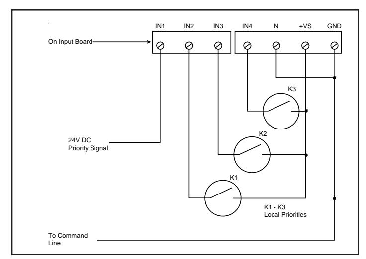
Figure 6. Connecting 24V DC Priority Signal to the Input Board for Activation of External Audio Signal Connected to Audio Input Board (Figure 8)
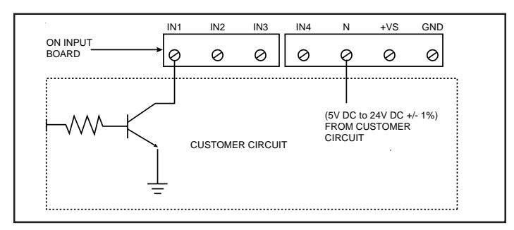
Figure 7. Installing with an open collector transistor for 24V DC tone initiation to IN1, IN2, IN3 or IN4
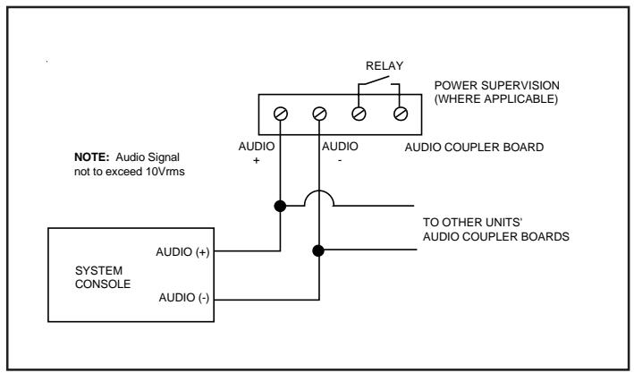
Figure 8. Connecting Audio Signal, not to exceed 10Vrms, from Tone Generator to 5536M Audio Input Board
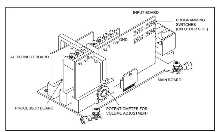
Figure 9. PC Board Locations
P/N 3100009 ISSUE 2 Page 4
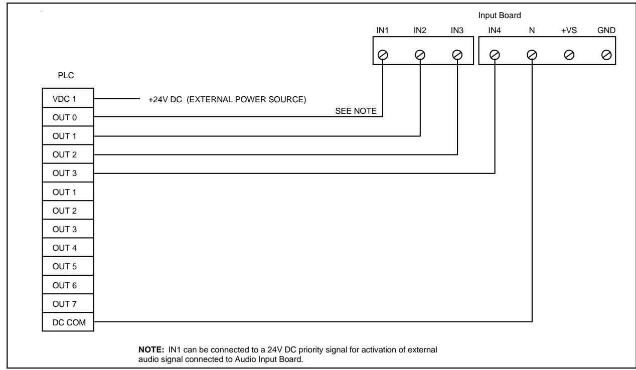
Figure 10. Connecting 24V Input Board to a PLC. See Table 1.
Figure 11. Tone Programming
| Switch | |||||||
|---|---|---|---|---|---|---|---|
| Tone | Description | 1 | 2 | 3 | 4 | 5 | HEX |
| No Tone | 00 | ||||||
| Ding-Dong | Percussive pairs of 700 and 570 Hz tones, each damped to zero | 01 | |||||
| Warble | 575 and 770 Hz alternately, 87 ms each | 02 | |||||
| Siren | 600-1250 Hz up and down sweep in 8 seconds and repeat | 03 | |||||
| Stutter | Percussive 470 Hz, 83 ms on, 109 ms off | 04 | |||||
| Slow Whoop | 600-1250 Hz upward sweep in 4 seconds and repeat | 05 | |||||
| Beep | 470 Hz, 0.55 seconds on, 0.55 seconds off | 06 | |||||
| Chime 1 | 700 Hz percussive repeat at 1 Hz | 07 | |||||
| Fast Whoop | 600-1250 Hz upward sweep in 1 second and repeat | 08 | |||||
| Hi/Lo | 780 to 600 Hz alternately, 0.52 seconds each | 09 | |||||
| Rapid Siren | 600-1250 Hz up and down sweep in 0.25 seconds and repeat | 0A | |||||
| Yeow | 1250-600 Hz downward sweep in 1.6 seconds and repeat | 0B | |||||
| Horn | 470 Hz continuous | 0C | |||||
| Air Horn | 370 Hz continuous | 0D | |||||
| Dual Tone | 450-500 Hz, 0.4 to 0.5 second cycle | 0E | |||||
| Chime 2 | 575 Hz percussive repeat at 1 Hz | 0F | |||||
| Westminster | Two measures, 411 Hz, 520 Hz, 407 Hz, 312 Hz | 10 | |||||
| Three Blind Mice | Four Measures, 787 Hz, 714 Hz, 625 Hz, 952 Hz, 333 Hz | 11 | |||||
| Phasor | 416-625 Hz up and down sweep in 13 ms and repeat | 12 | |||||
| Telephone | 570 and 770 Hz alternately, 50 ms each for 1.2s, 1.5s delay and repeat | 13 | |||||
| Staircase | 440-2000 Hz up and down steps, 750 ms delay and repeat | 14 | |||||
| 3 Tone Alert | 463, 641 and 896 Hz, 200 ms each, 1 second delay and repeat | 15 | |||||
| Presignal Chime | 470 Hz percussive repeat at 1.5 Hz, followed by Message 1 | 16 | |||||
| NFPA Whoop | 422-775 Hz, upward sweeps, 850 ms each, 1 second delay and repeat | 1B | |||||
| 3 Pulse Horn |
470 Hz, 3 0.5 second pulses separated by 0.5 seconds followed
by a 1.5 second delay and repeatFor Evacuation Use Only |
1C | |||||
| 3 Pulse Air Horn |
370 Hz, 3 0.5 second pulses separated by 0.5 seconds followed
by a 1.5 second delay and repeatFor Evacuation Use Only |
1D | |||||
| 3 Pulse Dual Tone |
450-500 Hz, 0.4 to 0.5 second cycle, 3 0.5 second pulses separated
by 0.5 seconds followed by a 1.5 second delay and repeatFor Evacuation Use Only |
1E | |||||
| 3 Pulse Chime 2 |
575 Hz, 3 0.5 second pulses separated by 0.5 seconds followed
by a 1.5 second delay and repeatFor Evacuation Use Only |
1F |
CAUTION
The use of evacuation signals on this product, that is not specifically Listed for Fire Alarm Use, is subject to the approval of the Authority Having Jurisdiction.
P/N 3100009 ISSUE 2 Page 5