Edwards Signaling 5530M-485 Installation Instructions
Open the original PDF document
View PDF

Installation Instructions for Catalog Series 5530M-485 Adaptatone® Millennium Signal
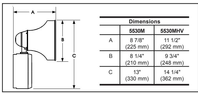
Figure 1. Dimensions
Description and Operation
Edwards Adaptatone is a heavy-duty, tone-selectable, stand alone, indoor/outdoor audible signaling device intended for industrial applications where high audible output and microcomputer reliability are required. The Adaptatone Millennium series are UL and cUL Listed as Audible Signal Appliances for use in the following hazardous locations.
|
Catalog
Number |
Hazardous
Locations |
Temp.
Code |
|---|---|---|
| 5530M-485Y6 | Class I, Div. 2, Groups A, B, C, D | T4 (135C) |
|
5530MHV-485Y6
5530MV-485Y6 |
Class II, Div. 2, Groups F, G
Class III, Div. 1 and 2 |
T5 (100C) |
The Adaptatone operates from local power and sounds a high decibel signal determined by the setting of miniature programming switches inside the unit. The Adaptatone may be programmed for any of the 27 tones listed in Figure 7.
Speaker direction and the output level are easily adjustable.
Mechanical Specifications
| Weight | 9 Pounds (4.1 kg) |
|---|---|
|
Hazardous Locations, UL Stand
Ambient Temp +4 |
|
|
Non-Hazardous Locations
Variable Ambient Temp41 |
OF to +151F (-40C to +66C) |
Electrical Specifications
| Catalog | Current (A) | |||
|---|---|---|---|---|
| Number | Voltage | Standby | Tone On | |
| Standard Volume | ||||
| 5530M-485Y6 | 125V DC | 0.10 | 0.21 | |
| 250V DC | 0.02 | 0.10 | ||
| 120V AC 50/60 Hz | 0.10 | 0.32 | ||
| 240V AC 50/60 Hz | 0.10 | 0.20 | ||
| 5530MHV-485Y6 | 125V DC | 0.10 | 0.39 | |
| 250V DC | 0.02 | 0.19 | ||
| 120V AC 50/60 Hz | 0.10 | 0.56 | ||
| 240V AC 50/60 Hz | 0.10 | 0.34 | ||
| 5530MV-485Y6 | 125V DC | 0.10 | 0.20 | |
| 250V DC | 0.02 | 0.10 | ||
| 120V AC 50/60 Hz | 0.10 | 0.31 | ||
| 240V AC 50/60 Hz | 0.10 | 0.20 | ||
Installation
The Adaptatone may be mounted to any flat surface or may be used as a freestanding unit mounted to a rigid pipe. The Adaptatone must be installed in accordance with the latest edition of the National Electrical Code or other regulations applicable to the country and locality of installation and by a trained and gualified electrician.

CAUTION
During installation, care must be taken so that components on the printed circuit board are not damaged.
-
1. Mount Adaptatone as shown in Figure 2.
- a. Flat Surface Mounting . Secure unit to mounting surface using the (4) mounting holes in the mounting plate on the rear of the box. Use the #10 x 3" (76 mm) wood screws (furnished loose) or other hardware (not supplied) suitable for the mounting surface.
- b. Rigid Pipe Mounting . Loosen the (4) cover screws from the signal box and lift off signal box cover.
NOTE: Cover screws are captive. Do not remove from cover.
Remove the center knockout in lower wall of box and mount box to a 1/2" (12.7 mm) conduit pipe using suitable connector.
2. Install wires through a knockout hole in the bottom of the box from a raceway that is, with its connections to the 1/2" (12.7 mm) conduit knockout hole, approved for the same degree of protection and enclosure type needed by the application. Use the provided plastic tie-wrap, on the barrier to the electronics, to separate incoming power leads from signal and tone initiating leads, per NEC (Figure 5).
WARNING
To prevent fire and shock, wire the Adaptatone only as described in this installation instruction.
-
3. Wire as follows referring to Figures 5 and 6.
- a. Connect green and yellow-striped earth-ground wires to earth-ground.
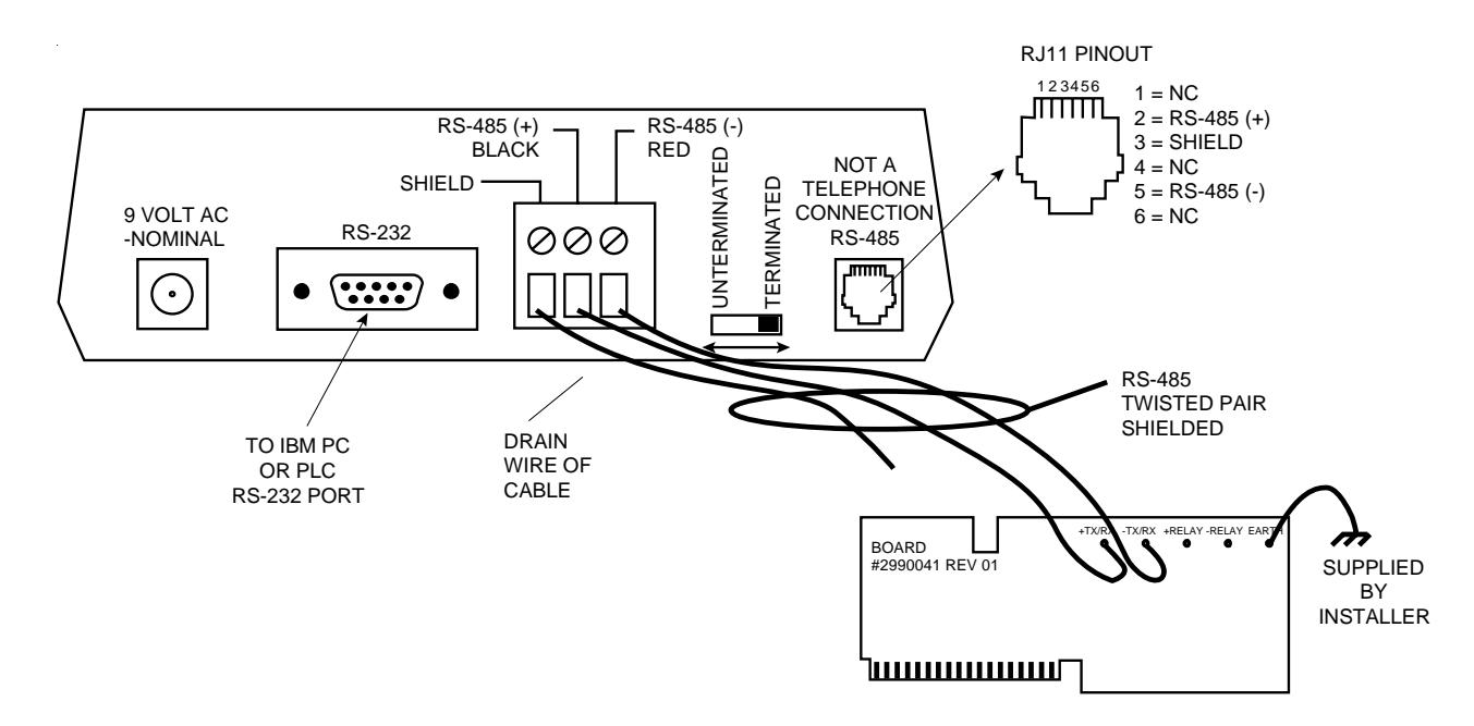
- b. Connect the RS485 wires to terminals +TX/RX and -TX/RX on the RS485 COMM board (Figure 6).
- c. If using the optional MR201/C relay, connect the relay to +RELAY and -RELAY on the RS485 COMM board (Figure 6).
- d. Connect incoming power to wire leads using a butt splice or other method listed, certified, or otherwise approved by local authorities. Leads are black and white.
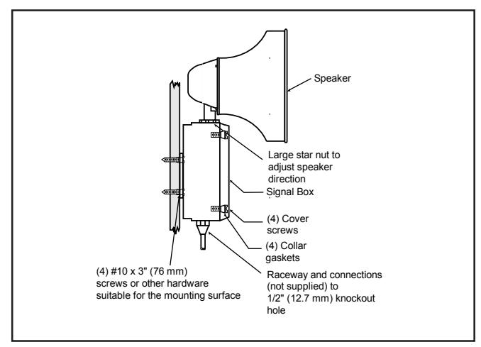
Figure 2. Adaptatone Mounting
e. Optional. Connect external 24V DC battery (not supplied) in series with separate diode assembly part 2600010 (supplied) to TB1 terminals 3 and 4 on the main board as shown in Figures 3 and 4 and marked on the diode assembly.
NOTE: Terminal Block TB1 can be unplugged from the main board to complete wiring as shown in Figure 3.
A
WARNINGS
HIGH VOLTAGE is present when product is energized. High volume may cause harm to personnel in close proximity.
5. Adjust volume level, if desired, by turning potentiometer located on the main board (Figure 11).
A
WARNING
To ensure integrity of the enclosure: Ensure the cover gasket, part number P-007549-0069, is adhered into groove at cover perimeter before replacing the signal box cover.
Ensure that the (4) collar gaskets, part number P-041930-0362, are in place on each cover screw before securing the signal box cover.
When securing cover, start screws by hand, making sure they are threaded into tapped holes in housing bosses before securing with a screwdriver. Torque signal box cover screws to a minimum of 20 in-lbs. This ensures the required tight fit.
- Tightly secure the signal box cover using (4) retained cover screws.
- 7. Torque signal box cover screws to a minimum of 20 in-lbs.
A
WARNING
To ensure integrity of the Adaptatone assembly when adjusting the speaker direction, make sure threads in the enclosure remain fully engaged and do not turn speaker more than 360 degrees from the original factory installed position.
8. To adjust speaker direction, loosen large star nut (Figure 2) and turn speaker to the approximate desired position.
A
WARNING
To ensure integrity of the Adaptatone assembly, prior to completion of installation, make sure threads in the enclosure are fully engaged and ensure that the star nut is wrench tight.
- 9. Regardless of speaker direction adjustment, it is important that the star nut be tightened wrench tight to ensure the speaker position is maintained securely.
- 10. Verify operability.
- 11. For tone selection and operation, refer to Figure 7 and the " Protocol " section of these installation instructions.
Maintenance and and Test
CAUTION
Ensure that power is disconnected before cleaning inside of unit.
Examine the unit semi-annually for accumulation of dirt. Clean if necessary.
The Adaptatone should be tested annually or as required by the authority having jurisdiction to ensure continuous service.
Protocol Protocol
1.0 Setting Unit Address and Network Baud Rate
- 1.1 Locate the 8-position dip switch, S1, on the top edge of the RS485 COMM board (Figure 6).
- 1.2 Unit address range is 00-1F hex. (00-31 decimal). Refer to Table 2.2 for unit address configuration. Set S1 positions 1-5 for the desired unit address configuration.
| Table 2.2 Unit Address Switch Configuration | |
|---|---|
| Unit Address | S1-1 | S1-2 | S1-3 | S1-4 | S1-5 | |
|---|---|---|---|---|---|---|
| Hex | Decimal | |||||
| 00 | 00 | OPEN | OPEN | OPEN | OPEN | OPEN |
| 01 | 01 | CLOSED | OPEN | OPEN | OPEN | OPEN |
| 02 | 02 | OPEN | CLOSED | OPEN | OPEN | OPEN |
| 03 | 03 | CLOSED | CLOSED | OPEN | OPEN | OPEN |
| 04 | 04 | OPEN | OPEN | CLOSED | OPEN | OPEN |
| 05 | 05 | CLOSED | OPEN | CLOSED | OPEN | OPEN |
| 06 | 06 | OPEN | CLOSED | CLOSED | OPEN | OPEN |
| 07 | 07 | CLOSED | CLOSED | CLOSED | OPEN | OPEN |
| 08 | 08 | OPEN | OPEN | OPEN | CLOSED | OPEN |
| 09 | 09 | CLOSED | OPEN | OPEN | CLOSED | OPEN |
| 0A | 10 | OPEN | CLOSED | OPEN | CLOSED | OPEN |
| 0B | 11 | CLOSED | CLOSED | OPEN | CLOSED | OPEN |
| 0C | 12 | OPEN | OPEN | CLOSED | CLOSED | OPEN |
| 0D | 13 | CLOSED | OPEN | CLOSED | CLOSED | OPEN |
| 0E | 14 | OPEN | CLOSED | CLOSED | CLOSED | OPEN |
| 0F | 15 | CLOSED | CLOSED | CLOSED | CLOSED | OPEN |
| 10 | 16 | OPEN | OPEN | OPEN | OPEN | CLOSED |
| 11 | 17 | CLOSED | OPEN | OPEN | OPEN | CLOSED |
| 12 | 18 | OPEN | CLOSED | OPEN | OPEN | CLOSED |
| 13 | 19 | CLOSED | CLOSED | OPEN | OPEN | CLOSED |
| 14 | 20 | OPEN | OPEN | CLOSED | OPEN | CLOSED |
| 15 | 21 | CLOSED | OPEN | CLOSED | OPEN | CLOSED |
| 16 | 22 | OPEN | CLOSED | CLOSED | OPEN | CLOSED |
| 17 | 23 | CLOSED | CLOSED | CLOSED | OPEN | CLOSED |
| 18 | 24 | OPEN | OPEN | OPEN | CLOSED | CLOSED |
| 19 | 25 | CLOSED | OPEN | OPEN | CLOSED | CLOSED |
| 1A | 26 | OPEN | CLOSED | OPEN | CLOSED | CLOSED |
| 1B | 27 | CLOSED | CLOSED | OPEN | CLOSED | CLOSED |
| 1C | 28 | OPEN | OPEN | CLOSED | CLOSED | CLOSED |
| 1D | 29 | CLOSED | OPEN | CLOSED | CLOSED | CLOSED |
| 1E | 30 | OPEN | CLOSED | CLOSED | CLOSED | CLOSED |
| 1F | 31 | CLOSED | CLOSED | CLOSED | CLOSED | CLOSED |
PAGE 3 P/N 3100345 ISSUE 2
1.3 RS485 COMM supports 1200, 2400, 9600 and 19200 baud rate using 8 data bits and one stop bit. Parity is not supported. Refer to Table 1.3 for Baud Rate switch configuration. Set S1 positions 6-7 for the desired Baud Rate configuration.
Table 1.3 Network Baud Rate setting
| Baud Rate | S1-6 | S1-7 |
|---|---|---|
| 1200 | OPEN | OPEN |
| 2400 | CLOSED | OPEN |
| 9600 | OPEN | CLOSED |
| 19200 | CLOSED | CLOSED |
1.4 Set 100-ohm termination resistor (if required). Network termination is required if the unit is located at the beginning or end of the network bus. Termination reduces unwanted reflections caused by data signal propagation due to long wire runs. Refer to Table 1.4 for switch configuration. Set S1 position 8 for network termination if required.
Table 1.4 Termination setting
| Termination (100 ohms) | S1-8 |
|---|---|
| Enabled | CLOSED |
| Disabled | OPEN |
2.0 Messaging Format
2.1 The RS485 COMM utilizes the Edwards SigNet ASCII protocol for data messaging. Each unit is capable of consuming and/or producing messages from the master controller. SigNet message format is illustrated below.
<STX> <UA> <DDDD> <ZONE> <ETX> <CHKSUM>
| <21X> | every message (1 byte). |
|---|---|
|
|
Two byte ASCII representation of the hex Unit. Example - If unit address 0A is chosen, the two byte
|
|
|
ASCII data field. (4 bytes total). These bytes contain commands, tone/message and timed sequence data. |
|
|
Programmable unit Zone issued by the master or controlling computer |
| Range ASCII A-D (1 byte). Note – Zone value is not retained after power loss unless battery backup is installed. Value defaults to Zone A on power up. | |
|
|
The
|
3.0 Message Command Set
3.1 Tone/Message Command - 00-1F
<UA>
<CHKSUM>
Send Format: <STX><UA><TONE> <TIME> <ZONE> <ETX> <CHKSUM>
<TONE> Tone/Message to be played by the unit. Example - If tone 06 is chosen, the two byte <TONE> data field should contain ASCII '0' and '6' written in ASCII format as 06. Range ASCII 00-1F(2 bytes). See Tone Chart for a list of available tones or
Unit address characters (2 bytes). See Section 2.0, Messaging Format
messages.
<TIME> Time sequence for Tone/Message to be played (00-99 seconds). For continous play
of Tone/Message, use '00' in this data field. Range ASCII 00-99 (2 bytes)
<ZONE> Units matching this zone field will play Tone/Message indicated in the <TONE>
data field for specified time indicated in <TIME> data field. All other zones remain
Optional two byte Message Block checksum (2 bytes). Refer to Section 4.0 for Block checksum calculation and verification. If checksum is not desired, must pad
in standby mode.
P/N 3100345 ISSUE 2 PAGE 4
these two bytes with two ASCII zeros 00.
<ETX> The <ETX> character has a value of 3 hexadecimal and is required at the end of
every message (1 byte)
<CHKSUM> Optional two byte Message Block checksum (2 bytes). Refer to Section 4.0 for
Block checksum calculation and verification. If checksum is not desired, must pad
these two bytes with two ASCII zeros 00.
3.2 BROADCAST COMMAND - 41
Send Format: <STX> 41 <TONE> <TIME> <ZONE> <ETX> <CHKSUM>
<41> In this command type, two byte ASCII '41' replaces <UA> characters. This command
is issued to all units containing the identical <ZONE> field.
<TONE> Tone/Message to be played by the unit. See tone chart for a list of available tones/
messages. Range ASCII 00-1F (2 bytes).
<TIME> Time sequence for Tone/Message (00-99 seconds). For continuous play of Tone/
Message, use '00' in this data field. Range ASCII 00-99 (2 bytes)
<ZONE> Units matching this zone field will play Tone/Message indicated in the <TONE>
data field for specified time indicated in <TIME> data field. All other zones remain
in standby mode.
<ETX> The <ETX> character has a value of 3 hexadecimal and is required at the end of
every message (1 byte)
<CHKSUM> Optional two byte Message Block checksum (2 bytes). Refer to Section 4.0 for
Block checksum calculation and verification. If checksum is not desired, must pad
these two bytes with two ASCII zeros 00.
Unit Response: None
Example: <STX>410530B<ETX>00
Units programmed with Zone 'B' only to play Tone 05 for 30 seconds then shut off
automatically. Checksum characters not used in this example.
Note: do not use spaces between message characters in the above example.
3.3 POLL COMMAND and SET UNIT ZONE - 43
Send Format: <STX><UA>43<00><ZONE><ETX><CHKSUM>
<UA> Unit address, ASCII Range 00-1F (two bytes)
<43> Two byte ASCII Command denoting POLL Command or Zone Assignment (2 byte).
<00> Two byte ASCII '00' used as protocol padding (two byes)
<ZONE> Programmable unit zone character. Range ASCII A-D. (1byte)
<ETX> The <ETX> character has a value of 3 hexadecimal and is required at the end of
every message (1 byte)
<CHKSUM> Optional two byte Message Block checksum (2 bytes). Refer to Section 4.0 for
Block checksum calculation and verification. If checksum is not desired, must pad
these two bytes with two ASCII zeros 00.
Unit Response: <STX><UA>43<STATUS><ZONE><ACK><ETX><CHKSUM>
<UA> Unit address, ASCII Range 00-1F (two bytes)
<43> Two byte ASCII Command echoed back from receiving unit (2 byte).
<STATUS> Unit's current diagnostic state. Range ASCII A - D. (1byte)
A = Tone/Message is active and Local Power is absent
B = Tone/Message is active and Local Power is present
C = Tone/Message is not active and Local Power is absent
D = Tone/Message is not active and Local Power is present
<ZONE> Unit's programmed zone character
<ACK> This <ACK> character has a value of 6 hexadecimal and represents
acknowledgement of the received command with valid checksum (1byte).
PAGE 5 P/N 3100345 ISSUE 2
Note: In the event that a bad checksum is calculated, by the receiving unit, it will reply with a <NAK> character instead. The <NAK> character has a value of 15 hexadecimal.
<ETX> The <ETX> character has a value of 3 hexadecimal and is required at the end of
every message (1 byte)
<CHKSUM> Receiving unit calculates two-byte checksum and returns ASCII value. Refer to
Section 4.0 for Block checksum calculation and verification.
Example 1: <STX>014300A<ETX>00
Unit 01 is being polled and programmed to Zone A
Unit Response: <STX>0143DA<ACK><ETX>56
The unit returned a <STATUS> 'D' for its current diagnostic state and an <ACK> character because both message and checksum are valid. The unit is not actively playing Tone/Message. The calculated two-byte message checksum was '56'.
Example2: <STX>014300A<ETX>00
Unit 01 is being polled and programmed to Zone A. Unit 01 is currently playing a
Tone/Message.
Unit Response: <STX>0143BA<ACK><ETX>54
The unit returned a <STATUS> 'B' for its current diagnostic state and an <ACK> character. The unit is actively playing a Tone/Message at the time this command was received. The calculated two-byte message checksum was '54'.
3.4 TIME SEQUENCE, TIME REMAINING COMMAND - 44
Send Format: <STX><UA>44 00 <ZONE> <ETX> <CHKSUM>
<UA> Unit address characters (2 bytes). See Section 2.0, Messaging Format
<44> Two byte ASCII Command denoting a Time Sequence (2 bytes).
<00> Two byte ASCII '00' used as protocol padding (two byes)
<ZONE> Programmable unit Zone issued by the master or controlling computer
Range ASCII A-D (1 byte).
<ETX> The <ETX> character has a value of 3 hexadecimal and is required at the end of
every message (1 byte)
<CHKSUM> Optional two byte Message Block checksum (2 bytes). Refer to Section 4.0 for
Block checksum calculation and verification. If checksum is not desired, must pad
these two bytes with two ASCII zeros 00.
Unit Response: <STX><UA> 44 <TIME LEFT><ACK><ETX> <CHKSUM>
<UA> Unit address characters (2 bytes). See Section 2.0, Messaging Format
<44> Two byte ASCII Command 43 echoed back from the receiving unit (2 bytes).
<TIME LEFT> Represents seconds left, in hexadecimal format, until the unit stops playing active
Tone/Message. Range 00-63 hex (2 bytes). The unit's internal counter returns the time remaining in seconds represented by a two byte hexadecimal value in the
above data field.
Note: For non-timed events, the unit returns two ASCII zeros '00'.
<ACK> Unit received a complete message and checksum characters are valid.
Note: In the event that a bad checksum is calculated, by the receiving unit, it will reply with a <NAK> character instead. The <NAK> character has a value of 15
hexadecimal.
<ETX> The <ETX> character has a value of 3 hexadecimal and is required at the end of
every message (1 byte)
<CHKSUM> Receiving unit calculates two-byte checksum and returns ASCII value. Refer to
Section 4.0 for Block checksum calculation and verification.
Example 1: Prior to issuing Command 44, the master issues a 99 second timed sequence event
for Tone/Message 03 to play on unit address 1F.
Command: <STX>1F0399A<ETX>00
9 seconds after issuing command from above, the master issues the "Time Remaining" Command 44
Command: <STX>1F4400A<ETX>00 and the unit replies with the following message.
Reply: <STX>1F445A<ACK><ETX>5E
Value 5A (90 decimal) is the hexadecimal representation of seconds left before the timed sequence event completes and Tone/Message stops.
3.5 DEVICE TYPE COMMAND - 45
Send Format: <STX><UA>45<00> <ZONE> <ETX> <CHKSUM>
Unit address characters (2 bytes). See Section 2.0, Messaging Format
<45> Two byte ASCII Command 45 denoting receiving unit's Device type (2 bytes).
<00> Two byte ASCII '00' used as protocol padding (two byes)
<ZONE> Programmable unit Zone issued by the master or controlling computer
Range ASCII A-D (1 byte).
<ETX> The <ETX> character has a value of 3 hexadecimal and is required at the end of
every message (1 byte)
<CHKSUM> Optional two byte Message Block checksum (2 bytes). Refer to Section 4.0 for
Block checksum calculation and verification. If checksum is not desired, must pad
these two bytes with two ASCII zeros 00.
Unit Response: <STX> <UA> <DEVICE TYPE> <vXX> <ETX> <CHKSUM>
<UA> Unit address characters (2 bytes). See Section 2.0, Messaging Format
<45> Two byte ASCII Command 45 echoed back from the receiving unit (2 bytes).
<DEVICE TYPE> Device type is an ASCII string transmitted by the receiving unit that defines the
unit family product code. For Millennium devices, the return ASCII string is "M-
485". For Édward's Visual devices, the return ASCII string is "S-485".
<vXX> Receiving Unit's Firmware version and revision level.
<ETX> The <ETX> character has a value of 3 hexadecimal and is required at the end of
every message (1 byte).
<CHKSUM> Receiving unit calculates two-byte checksum and returns ASCII value. Refer to
Section 4.0 for Block checksum calculation and verification.
Example: Command: <STX>014500A<ETX>00
Response: <STX>01M-485v1.0<ETX>84
Unit address 01 returns "M-485" string and is configured with version 1, rev.0
firmware. Calculated two-byte checksum is '84'.
3.6 RELAY ENERGIZE COMMAND - 31
Send Format: <STX><UA>31<TIME> <ZONE> <ETX> <CHKSUM>
<UA> Unit address characters (2 bytes). See Section 2.0, Messaging Format
<31> ASCII Command 31 denoting Relay Energize (2 bytes).
<TIME> Time sequence for relay 'ON' duration (00-99 seconds). For Continuos 'ON', use
ASCII '00' in this data field. Range ASCII 00-99 (2 bytes)
<ZONE> Programmable unit Zone issued by the master or controlling computer
Range ASCII A-D (1 byte).
<ETX> The <ETX> character has a value of 3 hexadecimal and is required at the end of
every message (1 byte)
<CHKSUM> Optional two byte Message Block checksum (2 bytes). Refer to Section 4.0 for
Block checksum calculation and verification. If checksum is not desired, must pad
P/N 3100345 ISSUE 2
these two bytes with two ASCII zeros 00.
Response: <STX><UA>31<TIME> <ACK> <ETX> <CHKSUM>
PAGE 7
Example: <STX>1F3105<ACK><ETX>00
Unit address 1F energizes relay for 5 seconds then shut off automatically. Checksum
characters not used in this example.
<UA> Unit address
<31> Two byte ASCII Command 31 echoed back from receiving unit.
<TIME> Received two byte ASCII time value
<ACK> Unit received valid message and checksum
<ETX> The <ETX> character has a value of 3 hexadecimal and is required at the end of
every message (1 byte).
<CHKSUM> Receiving unit calculates two-byte checksum and returns ASCII value. Refer to
Section 5.0 for Block checksum calculation and verification.
Note: Relay output commands are only valid when there is no tone/voice message actively playing. Any tone/voice messages automatically overrides any relay output commands sent to the unit.
3.7 RELAY DE-ENERGIZE COMMAND - 30
Send Format: <STX><UA>30<00> <ZONE> <ETX> <CHKSUM>
<UA> Unit address characters (2 bytes). See Section 2.0, Messaging Format
<30> ASCII Command 30 denoting Relay De-Energize (2 bytes). <00> Two byte ASCII '00' used as protocol padding (two byes)
<ZONE> Assigned unit Zone. Range ASCII A-D (1 byte)
<ETX> The <ETX> character has a value of 3 hexadecimal and is required at the end of
every message (1 byte).
<CHKSUM> Receiving unit calculates two-byte checksum and returns ASCII value. Refer to
Section 4.0 for Block checksum calculation and verification.
Response: <STX><UA>3000 <ACK> <ETX> <CHKSUM>
Example: <STX>1F3000<ACK><ETX>43
Unit address 1F de-energizes relay output
<UA> Unit address
<30> Two byte ASCII Command 30 echoed back from receiving unit.
<00> Two byte ASCII '00' used as protocol padding (two byes)
<ACK> Unit received valid message and checksum
<ETX> The <ETX> character has a value of 3 hexadecimal and is required at the end of
every message (1 byte).
<CHKSUM> Receiving unit calculates two-byte checksum and returns ASCII value. Refer to
Section 4.0 for Block checksum calculation and verification.
4.0 Verify and Calculate Message Block Checksum
- 4.1 Message Block checksum can be verified by adding up all the hexadecimal characters in the received message string, excluding the first character <STX> and the very last two checksum characters.
- 4.2 The sum of these characters will produce a three-byte hexadecimal value. The higher order byte is not used and should be dropped. The lower two bytes are used for comparison to the received checksum characters. See example Message String received below:
Message String Received:

4.3 Calculating the checksum is done by first converting each ASCII character, found in the message string, to the hexadecimal equivalent and then summing these characters. See below.
| ASCII | HEXAD | ECIMAL |
|---|---|---|
| 0 | 0x30 | |
| 1 | 0x31 | |
| 4 | 0x34 | |
| 3 | 0x33 | |
| D | 0x44 | |
| Α | 0x41 | |
| √ (ACK) | 0x06 | |
| → (ETX) | 0x03 | |
| 0v1 FC | hovodooim |
0x1 56 hexadecimal total
4.4 Dropping the upper hexadecimal byte from the above total yields a final result of 56 hexadecimal. The calculated hexadecimal checksum value should match the ASCII value received in the message string. If it does not match, a possible error occurred during transmission and the message is considered unreliable. The master or controlling computer should try to resend the message again.
Example of a POLL Command 43 issued to unit 05, Zone B
<STX>054300B<ETX>
| ASCII | HEXAD | ECIMAL. |
|---|---|---|
| 0 | 0x30 | |
| 5 | 0x35 | |
| 4 | 0x34 | |
| 3 | 0x33 | |
| 0 | 0x30 | |
| 0 | 0x30 | |
| В | 0x42 | |
| 」 (ETX) | 0x03 | |
| 0x171 | hexadecimal total |
The calculated Message Block checksum are appended to the message string. Two bytes, ASCII 7 and ASCII 1, consume these two checksum data fields. See below.
Send format: <STX>054300A<ETX> 71
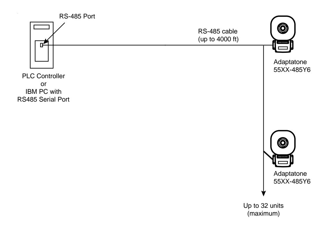
5.0 Wiring applications
RS-232 to RS-485 Multi or Single drop
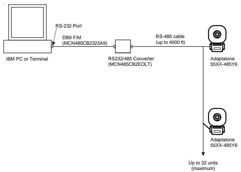
PAGE 9 P/N 3100345 ISSUE 2
PLC to RS-485 Multi or Single drop
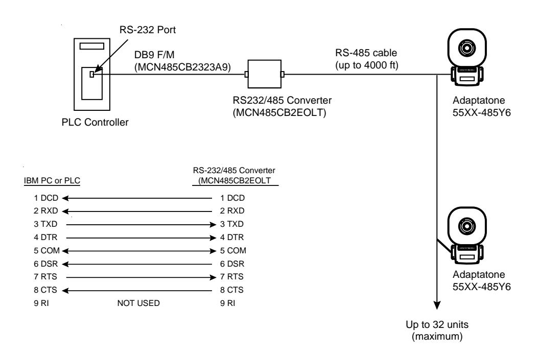
RS-485 Multi or Point to Point
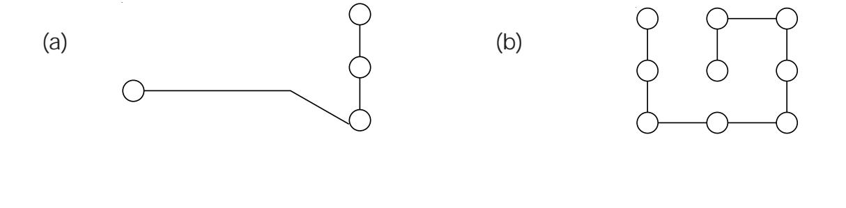
Suggested Network Topology Node Schemes

Wiring to RS-232/485 Convert Box (MCN485CB2EOLT)
PAGE 11 P/N 3100345 ISSUE 2
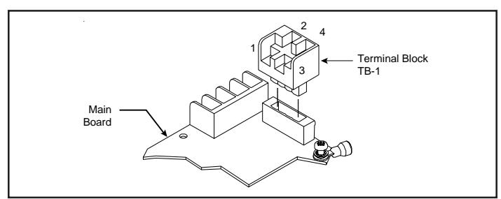
Figure 3. Terminal Block TB1
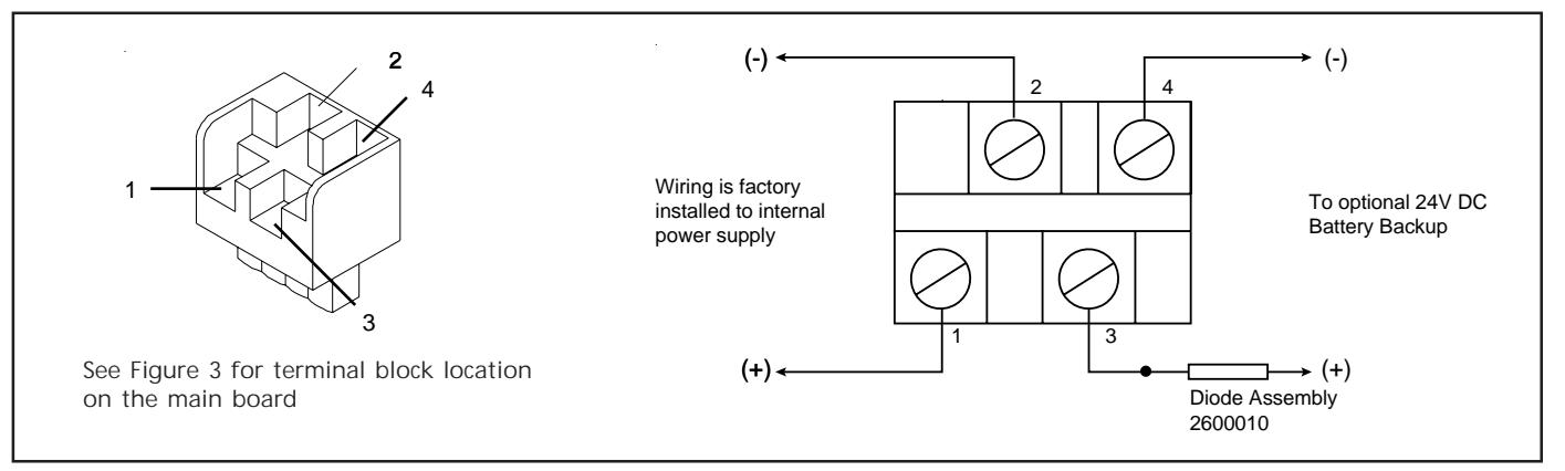
Figure 4. Wiring to Terminal Block TB1 Input Circuit
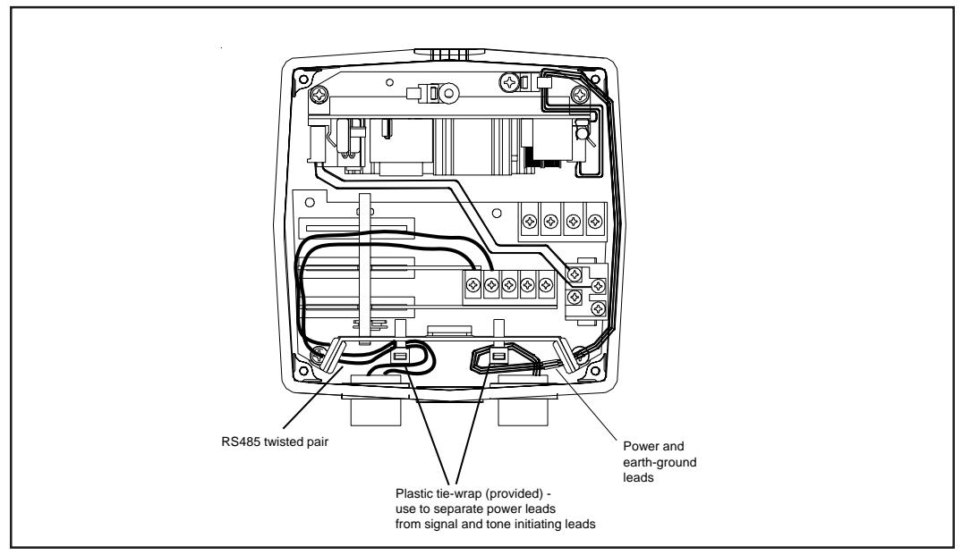
Figure 5. Wiring the Adaptatone
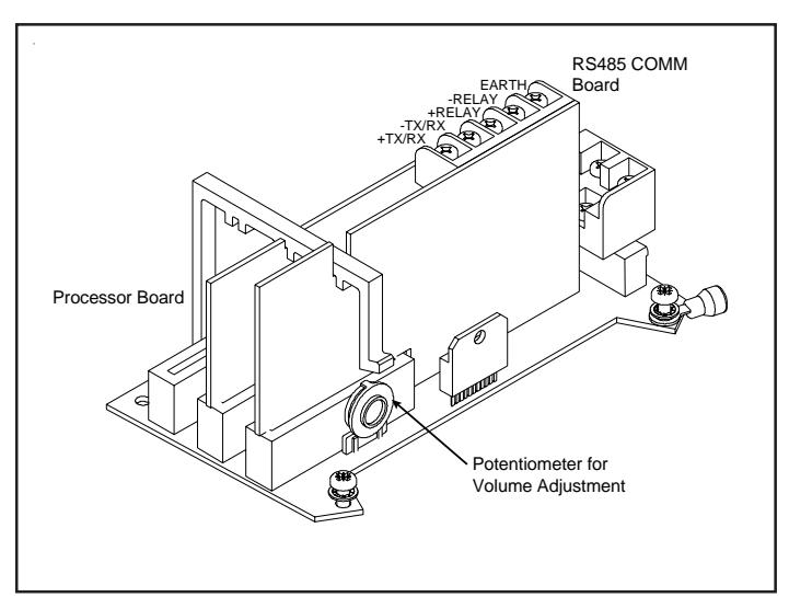
Figure 6. PC Board Locations
Figure 7. Tone Programming
| Switch | |||||||
|---|---|---|---|---|---|---|---|
| Tone | Description | 1 | 2 | 3 | 4 | 5 | HEX |
| No Tone | 00 | ||||||
| Ding-Dong | Percussive pairs of 700 and 570 Hz tones, each damped to zero | 01 | |||||
| Warble | 575 and 770 Hz alternately, 87 ms each | 02 | |||||
| Siren | 600-1250 Hz up and down sweep in 8 seconds and repeat | 03 | |||||
| Stutter | Percussive 470 Hz, 83 ms on, 109 ms off | 04 | |||||
| Slow Whoop | 600-1250 Hz upward sweep in 4 seconds and repeat | 05 | |||||
| Beep | 470 Hz, 0.55 seconds on, 0.55 seconds off | 06 | |||||
| Chime 1 | 700 Hz percussive repeat at 1 Hz | 07 | |||||
| Fast Whoop | 600-1250 Hz upward sweep in 1 second and repeat | 08 | |||||
| Hi/Lo | 780 to 600 Hz alternately, 0.52 seconds each | 09 | |||||
| Rapid Siren | 600-1250 Hz up and down sweep in 0.25 seconds and repeat | 0A | |||||
| Yeow | 1250-600 Hz downward sweep in 1.6 seconds and repeat | 0B | |||||
| Horn | 470 Hz continuous | 0C | |||||
| Air Horn | 370 Hz continuous | 0D | |||||
| Dual Tone | 450-500 Hz, 0.4 to 0.5 second cycle | 0E | |||||
| Chime 2 | 575 Hz percussive repeat at 1 Hz | 0F | |||||
| Westminster | Two measures, 411 Hz, 520 Hz, 407 Hz, 312 Hz | 10 | |||||
| Three Blind Mice | Four Measures, 787 Hz, 714 Hz, 625 Hz, 952 Hz, 333 Hz | 11 | |||||
| Phasor | 416-625 Hz up and down sweep in 13 ms and repeat | 12 | |||||
| Telephone | 570 and 770 Hz alternately, 50 ms each for 1.2s, 1.5s delay and repeat | 13 | |||||
| Staircase | 440-2000 Hz up and down steps, 750 ms delay and repeat | 14 | |||||
| 3 Tone Alert | 463, 641 and 896 Hz, 200 ms each, 1 second delay and repeat | 15 | |||||
| Presignal Chime | 470 Hz percussive repeat at 1.5 Hz, followed by Message 1 | 16 | |||||
| NFPA Whoop | 422-775 Hz, upward sweeps, 850 ms each, 1 second delay and repeat | 1B | |||||
| 3 Pulse Horn |
470 Hz, 3 0.5 second pulses separated by 0.5 seconds followed
by a 1.5 second delay and repeatFor Evacuation Use Only |
1C | |||||
| 3 Pulse Air Horn |
370 Hz, 3 0.5 second pulses separated by 0.5 seconds followed
by a 1.5 second delay and repeatFor Evacuation Use Only |
1D | |||||
| 3 Pulse Dual Tone |
450-500 Hz, 0.4 to 0.5 second cycle, 3 0.5 second pulses separated
by 0.5 seconds followed by a 1.5 second delay and repeatFor Evacuation Use Only |
1E | |||||
| 3 Pulse Chime 2 |
575 Hz, 3 0.5 second pulses separated by 0.5 seconds followed
by a 1.5 second delay and repeatFor Evacuation Use Only |
1F | |||||

CAUTION
The use of evacuation signals on this product, that is not specifically Listed for Fire Alarm Use, is subject to the approval of the Authority Having Jurisdiction.
PAGE 13 P/N 3100345 ISSUE 2