Edwards Signaling 5522D & 5523D Series Installation Instructions
Open the original PDF document
View PDF

INSTALLATION INSTRUCTIONS FOR DUOTRONIC® SIGNALS CATALOG NUMBERS 5522D-G1, 5523D-G1, 5524D-G1 AND 5525D-G1 FOR USE IN HAZARDOUS LOCATIONS
DESCRIPTION
Edwards' DUOTRONIC® signals, catalog numbers 5522D-G1, 5523D-G1, 5524D-G1, and 5525D-G1, are high decibel, diode-polarized signaling appliances intended for use in systems requiring electrical supervision of signaling circuit field wiring. The 5522D-G1 and 5524D-G1 models are horns, and the 5523D-G1 and 5525D-G1 models are sirens.
Models 5522D-G1 and 5523D-G1 are UL listed for use in Class I, Groups B, C and D locations, for both Divisions 1 and 2.
Models 5524D-G1 and 5525D-G1 are UL listed for use in Class I, Groups C and D; Class II, Groups E, F and G, and Class III locations, for both Divisions 1 and 2.
For all models, flange bolts are sealed in accordance with UL requirements to prevent disassembly and tampering.
ELECTRICAL AND MECHANICAL SPECIFICATIONS
The following specifications apply to all four DUOTRONIC signal models:
| Voltage | 24 V dc |
|---|---|
| Alarm Current | |
| Weight | |
| Dimensions | . Refer to Figure 1 |
INSTALLATION
- Assemble Unit. Fasten mounting bracket, bell, and re-entrant assembly to horn or siren driver using hardware provided. Refer to assembly instructions A-PP41944-0008 packaged with the unit.
- 2. Choose Mounting Location. The horn or siren may be mounted to any solid surface. Ensure that mounting location provides adequate clearance to enable adjustment of the signal to desired position after mounting. The signal position may be adjusted within an approximate 180-degree range vertically or horizontally depending on mounting of bracket.
- Install Unit. Mount unit in selected location using its mounting bracket and three bolts (not supplied). Refer to Figure 1 for size and location of mounting holes.
- Signal Direction Adjustment. To adjust signal direction, loosen two bolts, shown in Figure 1, rotate signal to desired position, and then tighten bolts.
-
5. Determine Signaling Circuit Wire Size. The signaling circuit wiring must be of adequate size to prevent excessive voltage drop that would affect signal performance. To determine the minimum wire size required:
- a. Calculate the value R<sub>max</sub>, as follows:
- Determine the total length of the signaling circuit wiring.
- c. Select a wire size having a resistance value that is less than the value R<sub>max</sub> for the length of signaling circuit wiring required. Approximate resistance values for 1,000 feet of several commonly used wire sizes are as follows: (AWG/ohms) 12/2.0, 14/3.2, 16/5.0, 18/8.0.
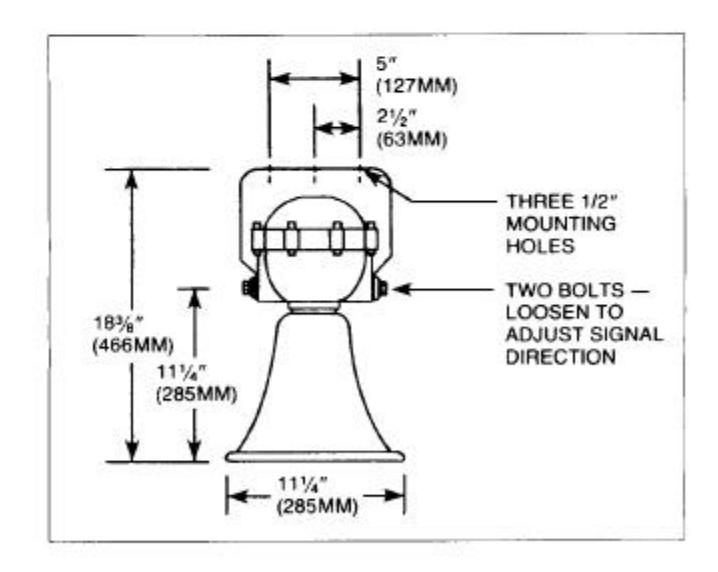
Figure 1. Signal Dimensions and Mounting Details
DUOTRONIC® is a registered trademark of Edwards Company, Inc.
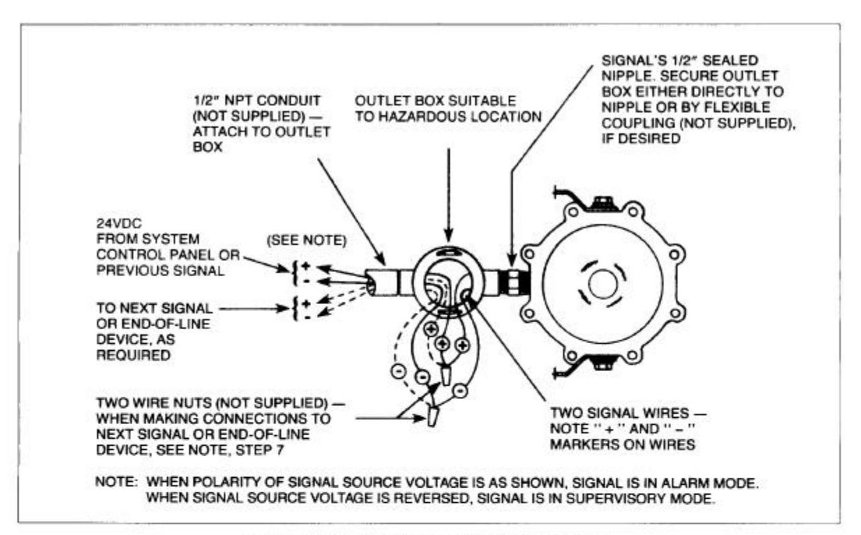
Figure 2. Wiring Installation and Connections
CAUTION
Do not apply power to the signal until installation is complete and cover is secure on conduit outlet box.
- 6. Install Wires. Refer to Figure 2. Remove cover from the conduit outlet box (not supplied). Note that the outlet box must be suitable for use in the hazardous location. Feed the two power supply wires from the system control panel or previous signal and the two wires to next signal or end-of-line device through a 1/2" NPT conduit (not supplied) into outlet box. Also, feed the two power connection wires from the horn or siren either directly into the outlet box or, if desired, through a 1/2" flexible type coupling (not supplied) and then into box. Secure outlet box to signal's sealed 1/2" nipple either directly or by flexible coupling, and secure conduit to outlet box.
- Connect Wires. Refer to Figure 2. Make power supply wiring connections and make wiring connections to next signal or end-of-line device in outlet box. Observe polarity of signal wires.
NOTE: When making wiring connections to next signal or end-of-line device, ensure that circuit wiring is cut to form separate incoming and outgoing wires at junctions with signal leads for proper supervision of connections.
Secure cover on outlet box.
Check Signal Operation. Apply power to the system control panel. Initiate an alarm to activate the signal and verify that it sounds. Then reset the panel and verify that the signal silences.
MAINTENANCE AND TEST
Examine the signal annually for accumulation of dirt and clean when necessary.
Test the signal annually or at the intervals required by applicable regulations and codes.
Edwards Company, Inc.
195 Farmington Avenue, Farmington, CT 06034