Edwards Signaling 5520D Series Installation Instructions
Open the original PDF document
View PDF

Installation Instructions for Duotronic Signals Catalog Numbers 5520D-AW and 5520D-N5
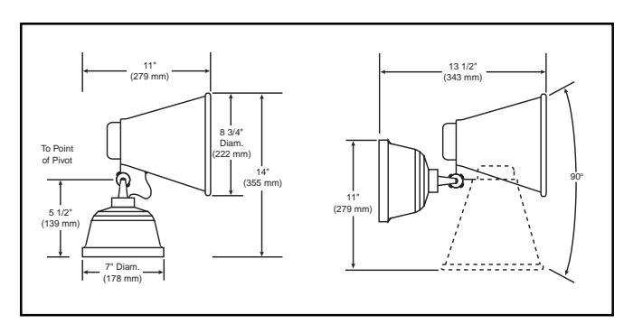
Figure 1. Dimensions
Description
Edwards' DUOTRONIC signals, catalog numbers 5520D-AW and 5520D-N5, are high decibel, diode-polarized, UL listed signaling appliances intended for public mode fire alarm signaling applications (per NFPA 72G) and other applications requiring electrical supervision of signaling circuit field wiring. The 5520D-AW signal is dc powered and the 5520D-N5 signal is ac powered. The signals can operate either as a horn or a siren and provide a switch for selecting the desired operating mode. The horn and siren tones are produced electronically. When operated in the horn mode, the signals can be used in coded signaling applications. The signals can be installed on any standard single gang, 3-1/4", 3-1/2", 4" octagonal or 4" square electrical box, or they can be installed outdoors using the Cat. No. 349 Weatherproof Box (ordered separately).
Electrical Specifications
| Catalog | Rated | Alarm | dBA Ratin | g at 10 ft* |
|---|---|---|---|---|
| Number | Voltage | Current (A) | Horn | Siren |
| 5520D-AW | 20 - 24V DC | 0.35 | 114 | 112 |
| 5520D-N5 | 120V AC | 0.35 | 114 | 112 |
* Sound level rating as measured in an anechoic chamber on an "A" weighted decibel scale.
Mechanical Specifications
| Dimensions | See Figure 1 |
|---|---|
| Weight | 7 1/2 Pounds (3.4 kg) |
Installation
1. Bring signaling circuit wires into electrical box or:
For weatherproof installation, fasten the Cat. No. 349 weatherproof box to the mounting surface by installing the (3) #8 x 1-1/4" wood screws and three fiber washers (supplied with the box) through the mounting holes in the rear of the box. Note that "TOP" inside of box indicates required position for installation. Bring signaling circuit wires through conduit and through conduit entrance hole into box. Secure conduit to box.
For indoor installation, select a site that conforms to the requirements given in the latest edition of NFPA 72, National Fire Alarm Code.
Disconnect the four-wire receptacle, shown in Figure 5, from the signal plug. Connect the leads from the receptacle to the signal circuit wires as shown in Figure 3 for the Cat. No. 5520D-N5 signal or Figure 4 for the 5520D-AW signal. Polarity must be observed.
CAUTION
Use all leads for connection. Make sure to break wire run to provide electrical supervision.
For additional information on wiring connections, refer to the installation instructions supplied with the fire alarm control panel or applicable system control panel.
See Figure 2. Loosen the screw at the bottom of the signal housing and remove the mounting plate from the signal.
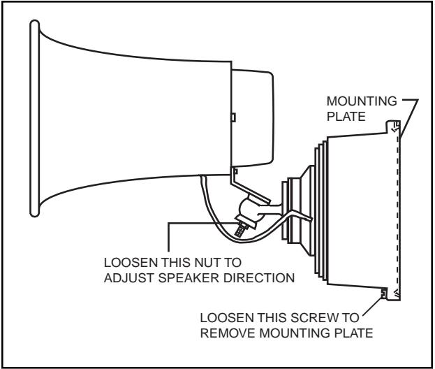
Figure 2. Mounting Plate Removal and Speaker Directional Adjustment
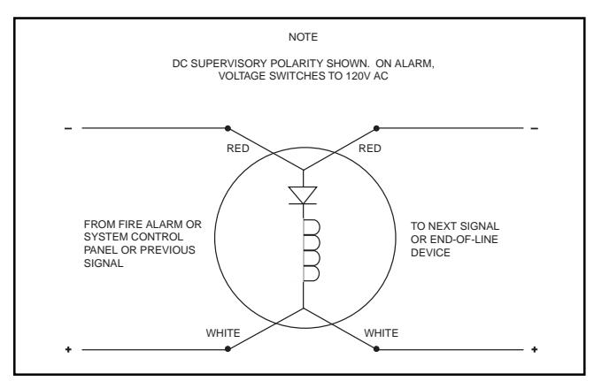
Figure 3. Wiring Diagram for Cat. No. 5520D-N5 Signal
operating the horn/siren switch.
- Select the desired operating mode by sliding the handle of the horn/siren switch, located in the rear of the signal housing, fully to the position marked "HORN" or "SIREN".
-
5. Bring the four-wire receptacle through the center hole of the mounting plate as shown in Figure 5. Align appropriate holes in plate with mounting screw holes in electrical box or with holes in bosses of Cat. No. 349 weatherproof box. Note that "TOP" on mounting plate indicates required position for installation. Fasten plate to applicable type of box as follows:
- a. To single gang box--using the two #6-32 x 5/8" screws supplied with signal.
- To octagonal or square box--using screws supplied with box.
- c. To weatherproof box--using the four #8-32 x 7/16" machine screws supplied with box.
- Connect the signal plug with the receptacle and push through mounting plate into box. Then hook signal on mounting plate by engaging hanger on plate, shown in Figure 5, into slot in top of signal housing. Tighten screw, loosened in step 3, to secure signal to plate.
Adjusting Speaker Direction
To adjust the speaker direction, loosen the nut shown in Figure 2. Rotate the speaker to the desired position and then tighten the nut. The speaker position can be adjusted within a 90 degree range vertically and 180 degree range horizontally.
Operational Test
Apply power to the fire alarm or system control panel. Initiate an alarm to activate the signal and verify that it sounds and that the selected type of signal is sounding. Reset the panel to silence the signal and return to the supervisory mode.
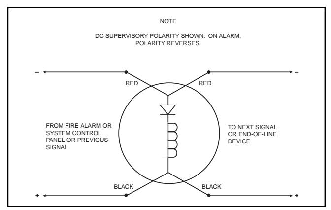
Figure 4. Wiring Diagram for Cat. No. 5520D-AW Signal
A WARNING
This device will not operate without electrical power. As fires frequently cause power interruptions, discuss further safeguards with your local fire protection specialist.
Maintenance and Subsequent Testing
Maintenance and testing of the 5520D-AW and 5520D-N5 Duotronic Signals should conform to the requirements given in the latest edition of NFPA 72. The standard requires you to examine the signal annually for accumulation of dust and dirt and clean when necessary.
Test the signal annually or at the intervals required by applicable fire regulations and codes.
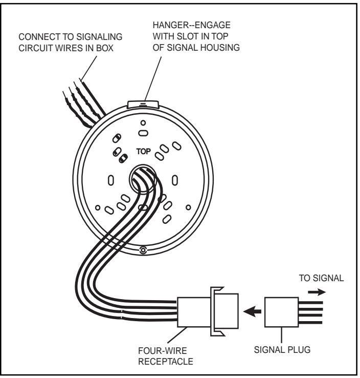
Figure 5. Mounting Plate Details