Edwards Signaling 332EX 333EX 340EX 435EX Installation Instructions
Open the original PDF document
View PDFDescription
Edwards Catalog Series 332EX, 333EX, 340EX and 435EX Adaptabel Bells are heavy duty, UL listed audible signaling appliances intended for use in hazardous locations. The 332EX and 333EX series are single stroke bells suitable for use in coded signaling applications such as timing, scheduling, paging, or alarm. The 340EX and 435EX series are vibrating bells suitable for use in general signaling and alarm applications. The 332EX and 340EX series are ac-powered and the 333EX and 435EX series are dc-powered. The bells are electromechanical devices and utilize solid state components. They are Outdoor Type 4 listed. All series of the bells are listed for installation in the following hazardous locations:
| Class | Zones | Divisions | Groups |
|---|---|---|---|
| I | 1 and 2 | B, C and D | |
| I | 1 and 2 | IIA and IIB | |
| II | 1 and 2 | E, F, and G | |
| III | 1 and 2 |
Electrical Specifications
| VIBRATI | N | 3 BELLS | |||||
|---|---|---|---|---|---|---|---|
| AC | DC | ||||||
| CAT. NO. |
RATED
VOLTAGE 50/60 HZ |
CURRENT
(RMS) |
CAT. NO. |
RATED
VOLTAGE |
CURRENT | ||
| 340EX-6G5 | 24V AC | 0.21A | 435EX-6C1 | 6V DC | 1.52A | ||
| 340EX-10G5 | 24V AC | 0.21A | 435EX-6E1 | 12V DC | 0.52A | ||
| 340EX-6N5 | 120V AC | 0.041A | 435EX-10E1 | 12V DC | 0.52A | ||
| 340EX-8N5 | 120V AC | 0.041A | 435EX-6G1 | 24V DC | 0.21A | ||
| 340EX-10N5 | 120V AC | 0.041A | 435EX-8G1 | 24V DC | 0.21A | ||
| 340EX-6R5 | 240V AC | 0.021A | 435EX-10G1 | 24V DC | 0.21A | ||
| 340EX-10R5 | 240V AC | 0.021A | 435EX-6K1 | 48V DC | 0.11A | ||
| 435EX-8K1 | 48V DC | 0.11A | |||||
| 435EX-6P1 | 125V DC | 0.040A | |||||
| 435EX-8P1 | 125V DC | 0.040A | |||||
| 435EX-6S1 | 250V DC | 0.023A | |||||
| 435EX-8S1 | 250V DC | 0.023A | |||||
| SINGLE ST | RC | OKE BELLS | |||||
| AC | DC | ||||||
| CAT. NO. |
RATED
VOLTAGE 50/60 HZ |
CURRENT
(PEAK) |
CAT. NO. |
RATED
VOLTAGE |
CURRENT
(PEAK) |
||
| 332EX-6G5 | 24V AC | 3.4A | 333EX-6G1 | 24V DC | 3.5A | ||
| 332EX-10G5 | 24V AC | 3.4A | 333EX-10G1 | 24V DC | 3.5A | ||
| 332EX-6N5 | 120V AC | 0.43A | 333EX-6P1 | 125V DC | 0.52A | ||
| 332EX-10N5 | 120V AC | 0.43A | 333EX-6S1 | 250V DC | 0.26A | ||
| 332EX-6R5 | 240V AC | 0.20A | |||||
| 332EX-10R5 | 240V AC | 0.20A | |||||
the gong size, i.e., 340EX-6G5 is a catalog series 340EX bell with a 6" gong.
Mechanical Specifications
Dimensions
With 6" gong ......7" (178 mm) H x 5" (127 mm) D With 8" gong 9" (229 mm) H x 5 1/8" (130 mm) D With 10" gong11" (279 mm) H x 5 1/4" (133 mm) D
Weight
| With 6" gong | 5 1/4 pounds (2.4 kg) |
|---|---|
| With 8" gong | |
| With 10" gong | 8 1/4 pounds (3.8 kg) |
Installation
The following items (not supplied) are required for installation of the bell:
- 3/4" conduit to contain power supply and ground wires
- One 3/4" NPT nipple
- One conduit outlet box suitable for use in the hazardous location
- Two fasteners up to 3/8" diameter and washers suitable for securing bell to mounting surface.
- Two wire nuts.
The bell can be mounted to any solid surface. Install bell as follows:
See Figure 1. Remove cover from conduit outlet box. Feed the two wires from the applicable power source
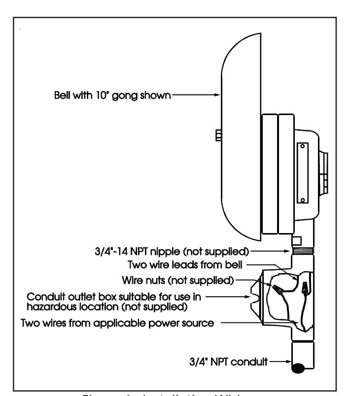
Figure 1. Installation Wiring
through conduit and into outlet box. Also, feed the bell's two wire leads through nipple and into box. Secure bell, nipple, and conduit to box.
Remove gong from bell. Place bell against mounting surface and mark mounting hole positions for fasteners per dimensions in Figure 2. Install fasteners with washers through mounting brackets and secure bell to surface. Replace gong in original orientation.
A
CAUTION
Do not apply power to the bell until installation has been completed and cover has been secured on outlet box.
3. Connect power supply wires to bell wires using wire nuts. For a dc-powered bell, observe polarity--red wire
- is positive (+), black wire is negative (-). Replace cover on outlet box.
- 4. Apply power to the bell and verify that it sounds.
Maintenance and Test
Examine the bell annually for accumulation of dirt and clean when necessary.
Test the bell annually or at the intervals required by applicable regulations and codes.
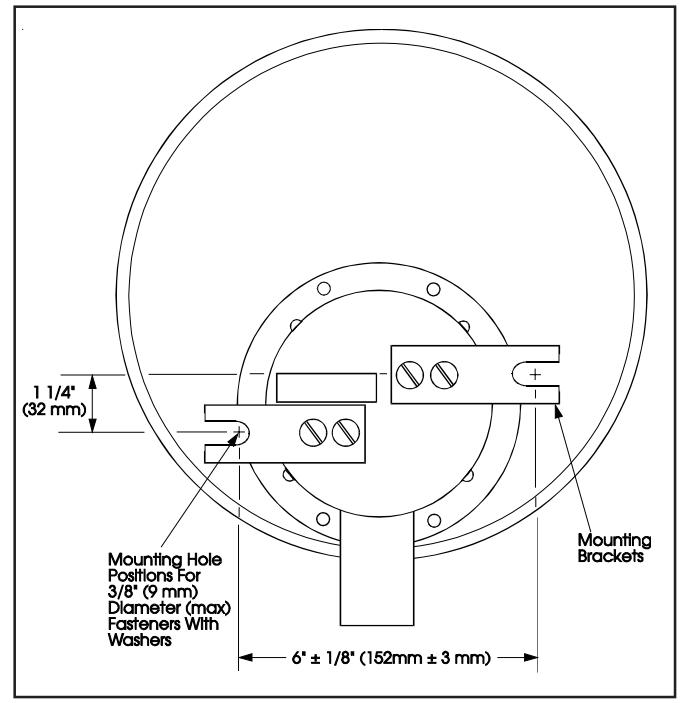
Figure 2. Dimensions for Mounting Hole Positions
P-047550-0585 ISSUE 6 PAGE 2