Edwards Signaling 108 Series Installation Instructions
Open the original PDF document
View PDF

Installation Instructions for 108 Series Chameleon Multi-Status Indicator
Description
The Edwards Chameleon Multi-Status Indicator is a UL and cUL listed, multi-color LED signaling appliance. The enclosure is Type 3R, 4X and IP65 rated.
The lights are available in 24V DC and 120V 50/60 Hz. They are available in either red, blue and amber or red, green and amber.
A pipe mount kit, Cat. No. 102PMF (sold separately) and one of three extension pipes (sold separately) allows the status indicator to be raised above the mounting surface for increased visibility.
The lights are designed such that any one or all three lights can be activated by either a PLC or contact closure. The first light activated will illuminate either steady or flashing (set by the internal jumper). If a second light is activated, the Chameleon cycles between the two colors. A third activation causes the Chameleon to cycle between all three colors: red, amber and green or red, amber and blue.
The Chameleon also features a multi-tone base module that allows the installer to select one of eight available tone options. The selected tone can be operated as a fourth signal or used in conjunction with any of the LED signals.
The Chameleon is also available with two shorter bases that are used when a lower profile is desired: one for surface mounting and one for pendant mounting. The shorter bases do not allow for use of a tone module.
An additional light module can be used on the Chameleon. For available lens modules and light sources, refer to Table 4.
PLC Compatibility
The electrical input characteristics for PLC compatible signals are listed in Table 2. Signals with these characteristics may be directly connected to PLC output cards that do not exceed these input characteristics.
Installation
Installation must be in accordance with the latest edition of the National Electrical Code and other governing standards and codes for standard installation.

WARNINGS
To prevent electrical shock, do not connect power until instructed to do so.
To prevent abrasion of wiring insulation, ensure that wire passage holes are adequately protected.
1. If using the 102PMF mounting kit, perform the following:
NOTE: All references below are to Figure 5.
Using the supplied gasket (D) as a guide, mark the four mounting holes and the center clearance hole on an appropriate surface.
- b. Punch the four mounting holes. Punch the wiring clearance hole in the mounting surface to be sufficiently larger than that in the gasket to ensure the wiring insulation is protected from abrasion by the gasket (without interfering with the mounting screw holes), or provide other appropriate wire insulation abrasion protection as needed.
- c. Screw the pipe extension (purchased separately) into the mounting flange.
- d. Ground the flange by pulling the ground wire through the mounting surface clearance hole and center hole of the gasket. Connect earth ground to the bottom of the base mount flange using the ground screw (G) and wire retention terminal cup washer (H).
- e. Pull the remaining field wiring through center clearance hole of mounting surface, center hole of the gasket, pipe mount flange and extension pipe.
- f. Align the mounting gasket (D) and flange (A) on the panel. Secure using (4) #10-24 x 1" (25 mm) pan head screws (B), (4) external tooth #10 star washers (E) and (4) #10-24 hex nuts (F).
- g. Mount the base as instructed below.
- 2. If not using the 102PMF mounting kit, install base on 3/4" (19 mm) conduit (not supplied). Pull field wiring through conduit entrance hole.
- 3. If not using the 102PMF mounting kit, mount using the appropriate method below.
NOTE: For indoor applications, the base may be panel mounted or conduit mounted. For NEMA3R, 4X, and outdoor applications, it is recommended that either the 108IP or 108I series be used.
- a. Cat. Series 108I Install base on 3/4" (19 mm) conduit (not supplied). Pull field wiring through conduit entrance hole.
- b. Cat. Series 108IP Install base on 3/4" (19 mm) conduit (not supplied). Pull field wiring through conduit entrance hole
- c. Cat. Series 108ID Using the supplied mounting gasket as a template, punch the four mounting holes. Punch the wiring clearance hole in the mounting surface to be sufficiently larger than that in the gasket to ensure the wiring insulation is protected from abrasion by the gasket (without interfering with the mounting screw holes), or provide other appropriate wire insulation abrasion protection as needed. Mount the base to the surface using the (2) screws (supplied).
-
4. Connect field wiring.
- a. Cat. Series 108I Connect field wiring to the terminal block as shown in Figure 1.
Connect additional field wiring to the terminal block mounted on the signal assembly as shown in Figure 2.
NOTE: The tone module may be wired to sound independently or in conjunction with an LED signal.
To sound tone module independently, connect to separate hot lead.
To sound tone module with a particular light source, connect horn hot terminal to selected light terminal on the terminal block.
- b. Cat. Series 108IP or Cat. Series 108ID Using wire nuts, connect 18" (457 mm) wire leads to field wiring. The wire leads are marked as follows: Neutral, Red, Blue (for models with Red, Amber and Blue LEDs) or Green (for models with Red, Amber and Green LEDs), Amber, and 2nd Module.
-
5. If using a second module, install as follows (see Figure 4):
- Loosen the captive screw in the cap and remove the cap from the unit.
- b. Pull the captive key in the second lens module into the "out" position.
- c. Place the second lens module on top of the first.
- d. Push in the captive key to secure the lens module.
- e. Insert the light source into board grooves at bottom of lens module, ensuring that the four prongs on the PC board are aligned with the plug located in the back of the lens assembly.

WARNING
To prevent leakage, ensure the magnifier ring on the lens cover and the magnifier ring on the lens module are aligned (Figure 4).
NOTE: When using LED light sources, ensure that the color of the LED light source and the lens assembly match.
- Place the lens assembly cover on the front of the lens module and secure using two captive screws.
- g. Replace the cap on top and secure the cap with the captive screw
- 6. If using the Cat. No. 108I, set the selected tone. See Table 3 and Figure 3.
- 7. Apply power to the unit and verify proper operation.
Maintenance
The lens surfaces should be periodically dusted and cleaned with a dry soft clean cloth to maintain optimum light visibility. If necessary, the outside of the lens may be cleaned with water and a mild detergent on a well rung-out, soft, clean cloth.
Table 1. Specifications
|
Catalog
Number |
Mounting | Voltage | Current |
Peak Inrush
Current |
Repetitive
Surge Current |
Colors |
|---|---|---|---|---|---|---|
| 108I-RGA-N5 | Pipe Mount | 120V 50/60 Hz | 0.115 A* | 30A @ 2 μs | 0.45A @ 2 ms (120 Hz) | red, green, amber |
| 108I-RBA-N5 | Pipe Mount | 120V 50/60 Hz | 0.115 A* | 30A @ 2 µs | 0.45A @ 2 ms (120 Hz) | red, blue, amber |
| 108I-RGA-G1 | Pipe Mount | 24V DC | 0.105 A* | 5A @ 1 ms | 0.275A @ 2 ms (500-1 kHz) | red, green, amber |
| 108I-RBA-G1 | Pipe Mount | 24V DC | 0.105 A* | 5A @ 1 ms | 0.275A @ 2 ms (500-1 kHz) | red, blue, amber |
| 108IP-RGA-N5 | Pipe Mount (Short Base) | 120V 50/60 Hz | 0.045 A | 13A @ 2 µs | 0.10A @ 4 ms (60 Hz) | red, green, amber |
| 108IP-RBA-N5 | Pipe Mount (Short Base) | 120V 50/60 Hz | 0.045 A | 13A @ 2 µs | 0.10A @ 4 ms (60 Hz) | red, blue, amber |
| 108IP-RGA-G1 | Pipe Mount (Short Base) | 24V DC | 0.055 A | 5A @ 1 ms | 55 mA | red, green, amber |
| 108IP-RBA-G1 | Pipe Mount (Short Base) | 24V DC | 0.055 A | 5A @ 1 ms | 55 mA | red, blue, amber |
| 108ID-RGA-N5 | Direct Mount | 120V 50/60 Hz | 0.045 A | 13A @ 2 µs | 0.10A @ 4 ms (60 Hz) | red, green, amber |
| 108ID-RBA-N5 | Direct Mount | 120V 50/60 Hz | 0.045 A | 13A @ 2 µs | 0.10A @ 4 ms (60 Hz) | red, blue, amber |
| 108ID-RGA-G1 | Direct Mount | 24V DC | 0.055 A | 5A @ 1 ms | 55 mA | red, green, amber |
| 108ID-RBA-G1 | Direct Mount | 24V DC | 0.055 A | 5A @ 1 ms | 55 mA | red, blue, amber |
* The current rating for the 108I series indicates an activated tone in the multi-tone module.
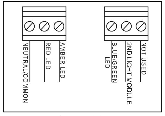
Figure 1. Wiring
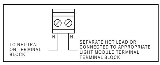
Figure 2. Wiring the Tone Module
Table 2. PLC Compatibility
| Cat. No. |
Operating
Voltage |
Max. off state
leakage current mA |
Continuous
on current mA |
Surge
(inrush/duration) A/mSeconds** |
|---|---|---|---|---|
|
108I-RBA-G1
108I-RGA-G1 |
24V DC | 5 | 0.105 | 0.24/0.2 |
|
108IP-RBA-G1
108IP-RGA-G1 108ID-RBA-G1 108ID-RGA-G1 |
24V DC | 5 | 55 | 0.070/8 |
|
108I-RBA-N5
108I-RGA-N5 |
120V AC | 5 | 0.115 | 0.35/0.2 |
|
108IP-RBA-N5
108IP-RGA-N5 108ID-RBA-N5 108ID-RGA-N5 |
120V AC | 5 | 45 | 0.100/8 |
* All AC volts at 60 Hz
NOTE: The values shown here are for units with only one Chameleon LED module. For information on units with an additional light module, please contact Applications Engineering.
Table 3. Switch Settings
| Switch Settings* | |||
|---|---|---|---|
| Tone | 1 | 2 | 3 |
| Stutter beep | OFF | OFF | OFF |
| Hi / Lo | ON | OFF | OFF |
| 3 Pulse Horn | OFF | ON | OFF |
| Continuous | OFF | OFF | ON |
| Yeow | ON | ON | OFF |
| Fast Whoop | ON | OFF | ON |
| Rapid Siren | OFF | ON | ON |
| Веер | ON | ON | ON |
* ON is in the "UP" position (see Figure 4).
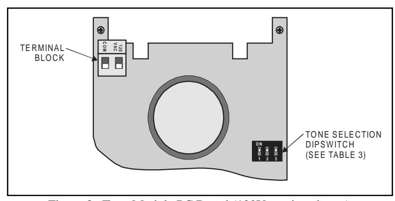
Figure 3. Tone Module PC Board (120V version shown)
** Amps/milliseconds
Table 4. Accessories and Replacement Parts
| Catalog | Manufacturers | Replacement | Lamp Life (hours) | |||
|---|---|---|---|---|---|---|
| Number | Voltage | Lamp Ratings | Lamp | Calculated# | Projected## | |
| Pipe Mount Flange | 102PMF | N/A | N/A | N/A | N/A | |
| Extension Pipes | 102MP-4 | N/A | N/A | N/A | N/A | |
| 102MP-10 | N/A | N/A | N/A | N/A | ||
| 102MP-15 | N/A | N/A | N/A | N/A | ||
| Add-On Lens Modules | 102LM-* | N/A | N/A | N/A | N/A | |
| Steady-On Halogen | 102LS-SINH-G1 | 24V DC | 9 Watts | 50LMP-9WH or Ind. Trade 303*** | 12,000 | |
| Steady-On Halogen | 102LS-SINH-N5 | 120V AC | 12 Watts | 50LMP-12WH | 20,000 | |
| Steady-On Incandescent | 102LS-SIN-G1 | 24V DC | 10 Watts | Ind. Trade 303 | 10,000 | |
| Steady-On Incandenscent | 102LS-SIN-N5 | 120V AC | 10 Watts | 50LMP-10W | 2,500 | |
| Flashing Halogen | 102LS-FINH-G1 | 24V DC | 9 Watts | 50LMP-9WH or Ind. Trade 303*** | 12,000 | 15,000 |
| Flashing Halogen | 102LS-FINH-N5 | 120V AC | 12 Watts | 50LMP-12WH | 20,000 | 25,000 |
| Flashing Incandescent | 102LS-FIN-G1 | 24V DC | 10 Watts | Ind. Trade 303 | 10,000 | 12,500 |
| Flashing Incandescent | 102LS-FIN-N5 | 120V AC | 10 Watts | 50LMP-10W | 2,500 | 3,000 |
| Strobe | 102LS-ST-G1 | 24V DC | 3 Joule Strobe | 3,000### | ||
| Strobe | 102LS-ST-N5 | 120V AC | 3 Joule Strobe | 3,000### | ||
| Steady-On LED | 102LS-SLED**-G1 | 24V DC | N/A | 100,000 | ||
| Steady-On LED | 102LS-SLED**-N5 | 120V AC | N/A | 100,000 | ||
| Flashing LED | 102LS-FLED**-G1 | 24V DC | N/A | 100,000 | ||
| Flashing LED | 102LS-FLED**-N5 | 120V AC | N/A | 100,000 | ||
* Signifies lens module color (A - amber, B - blue, C - clear, G - green, R - red)
### Strobe tube life @ operating power to 75% efficiency.
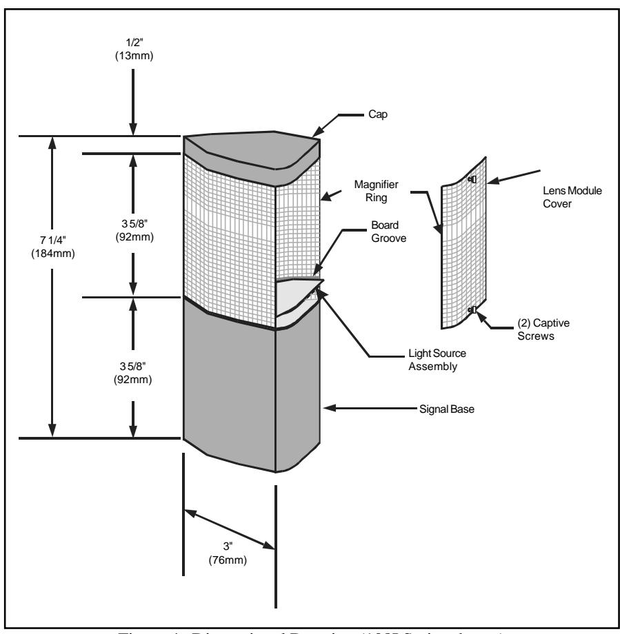
Figure 4. Dimensional Drawing (108I Series shown)
** Signifies lens and LED module color (A - amber, B - blue, G - green, R - red) NOTE: LED light sources must be used with the cooresponding color lens module (e.g., a blue LED light source, 102LS-SLEDB-G1, must be used with a blue lens, 102LM-B).
*** A non-halogen lamp, as listed, may be used in place of the halogen lamp.
# At nominal operating voltage.
## Projected lamp life based on manufacturer's calculated lamp life @ 65 fpm and 50% duty cycle.
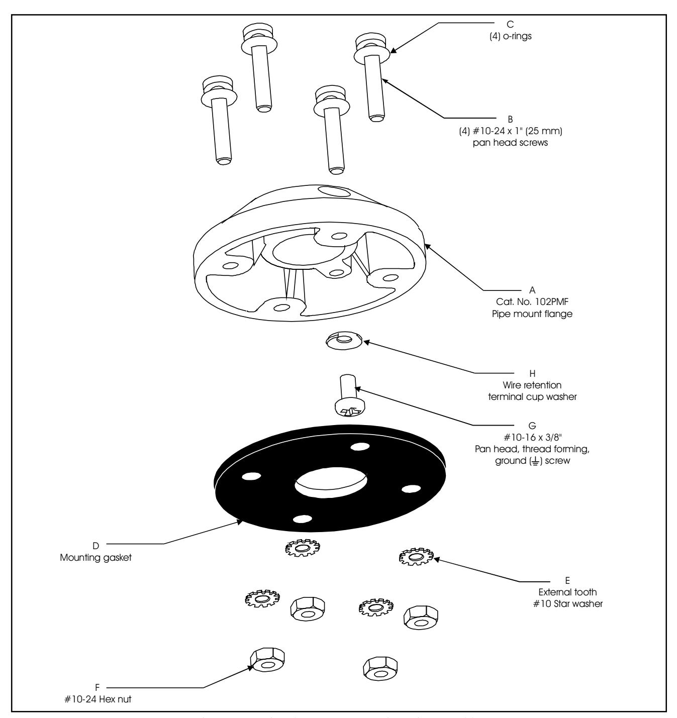
Figure 5. Optional 102PMF Mounting Kit Assembly
Contacting Edwards:
Phone: (203) 699-3000
E-Mail:
techsupport@edwards-signals.com customerservice@edwards-signals.com
http://www.edwards-signals.com Website: