Edwards Signaling 108-DN Series Installation Instructions
Open the original PDF document
View PDF

Installation Instructions for 108 Series Chameleon DeviceNet Status Indicating Lighting System
Description
The Edwards Chameleon DeviceNet Status Indicating Lighting System is a unique audible-visual signaling device that combines three LED visual and eight audible signals in one compact housing.
The Chameleon also features a multi-tone base module that contains eight tone options. The selected tones can be operated as independent signals or used in conjunction with any of the LED signals.
All components of the Lighting System are UL listed subassemblies and cUL Listed. The enclosures are NEMA 3R, NEMA 4X and IP65 Rated. The unit has been tested by ODVA's authorized independent test lab and found to comply with ODVA conformance test software.
The lens module contains a removable cover to allow for easy relamping. The lens module cover features a molded-in gasket for weather tight reliability.
See Tables 1 and 2 for specification information.
Device Profile
Revision 1.00 Firmware Revision 1.00
The DeviceNet interface is in the unit's base which interfaces between the network and the modules.
The Chameleon DeviceNet Status Indicator is a slave device. It is a general purpose status indicator designed to indicate the status of a machine or process.
Power to drive the LED light sources may be taken locally or from the DeviceNet Network. A standard open style 2 pin connector is used to connect 24V DC @ 0.105A (max) or 120V AC @ 0.12A (max).
The unisolated physical layer contains DeviceNet required mis-wiring protection circuitry. A standard open style (unsealed) 5 pin connector is used to connect the Status Indicator to the DeviceNet bus. The current draw from the bus is 0.12A.
The Chameleon DeviceNet Status Indicator contains a preprogrammed microcontroller which implements the Group 2 pre-defined Master/Slave Connection Set. This allows for one Explicit Messaging Connection and one Poll Connection. The objects (classes) supported are described in the next section. The Chameleon Status Indicator resets automatically when DeviceNet power is applied.
1.0 Object Model
1.1 Object present in the base:
| OBJECT | Optional/Required | # of Instances |
|---|---|---|
| Identity (1) | Required | 1 |
| Message Router (2) | Required | 1 |
| Devicenet (3) | Required | 1 |
| Assembly (4) | Required | 1 |
| Connection (5) | Required | 1 |
1.2 Object that Effect Behavior:
| OBJECT | Effect on Behavior |
|---|---|
| Identity (1) | Supports the reset service |
| Message Router (2) | No effect |
| Devicenet (3) | Configures port attributes |
| Assembly (4) | I/O assembly for lamps |
| Connection (5) | Establishes the number of connections |
1.3 Object Interfaces:
| OBJECT | Effect on Behavior |
|---|---|
| Identity (1) | Message router |
| Message Router (2) | Explicit message connection instance |
| Devicenet (3) | Message router |
| Assembly (4) | I/O connection or message router |
| Connection (5) | Message router |
1.4 Identification of I/O Assembly Interfaces:
| Instance Number | Туре | Name |
|---|---|---|
| 1 | Input/Output | LEDs ON/OFF, LED diagnostics, and sounder control |
1.5 Format of I/O Assembly data Attribute:
Input to the DeviceNet bus as a response to the poll command from master node.
Data Byte 0 value indicates the LEDs are OK or are burned out.
Data Byte 1 value indicates the LEDs were on or off when last poll command was received.
Data Byte 2 value indicates the current sounder module control value.
| BYTE | BIT7 | BIT6 | BIT5 | BIT4 | BIT3 | BIT2 | BIT1 | BIT0 |
|---|---|---|---|---|---|---|---|---|
| 0 |
DON'T
CARE |
DON'T
CARE |
DON'T
CARE |
DON'T
CARE |
DON'T
CARE |
LED 3
1 = REP 0 = OK |
LED 2
1 = REP 0 = OK |
LED 1
1 = REP 0 = OK |
| 1 |
DON'T
CARE |
DON'T
CARE |
DON'T
CARE |
DON'T
CARE |
DON'T
CARE |
LED 3
1 = ON 0 = OFF |
LED 2
1 = ON 0 = OFF |
LED 1
1 = ON 0 = OFF |
| 2 | 0 | 0 | 0 | 0 |
Sounder
1 = ON 0 = OFF |
Tone
MSB |
Tone |
Tone
LSB |
Output to the base with the poll command from master node.
Data Byte 0 value indicates the LEDs to be turned ON or OFF.
Data Byte 1 value indicates the ON LEDs to be Steady ON or Flashing and the Flashing rate (45, 60 or 80 flashes per minute) selected.
Data Byte 2 value indicates the sounder to be turned ON or OFF and the tone to be chosen.
| BYTE | BIT7 | BIT6 | BIT5 | BIT4 | BIT3 | BIT2 | BIT1 | BIT0 |
|---|---|---|---|---|---|---|---|---|
| 0 | DON'T | DON'T | DON'T | DON'T | DON'T | LED 3 | LED 2 | LED 1 |
| CARE | CARE | CARE | CARE | CARE | 1 = ON | 1 = ON | 1 = ON | |
| 0 = OFF | 0 = OFF | 0 = OFF | ||||||
| 1 | 0 | 0 | 1 | DON'T | DON'T | LED 3 | LED 2 | LED 1 |
| 45 | CARE | CARE | 1 = FLSH | 1 = FLSH | 1 = FLSH | |||
| FPM | 0 = STDY | 0 = STDY | 0 = STDY | |||||
| 1 | 0 | 1 | 0 | DON'T | DON'T | LED 3 | LED 2 | LED 1 |
| 60 | CARE | CARE | 1 = FLSH | 1 = FLSH | 1 = FLSH | |||
| FPM | 0 = STDY | 0 = STDY | 0 = STDY | |||||
| 1 | 1 | DON'T | DON'T | DON'T | DON'T | LED 3 | LED 2 | LED 1 |
| 80 | CARE | CARE | CARE | CARE | 1 = FLSH | 1 = FLSH | 1 = FLSH | |
| FPM | 0 = STDY | 0 = STDY | 0 = STDY | |||||
| 1 | 0 | 0 | 0 | DON'T | DON'T | LED 3 | LED 2 | LED 1 |
| 80 FPM | 80 FPM | 80 FPM | CARE | CARE | 1 = FLSH | 1 = FLSH | 1 = FLSH | |
| DEFLT | DEFLT | DEFLT | 0 = STDY | 0 = STDY | 0 = STDY | |||
| 2 | 0 | 0 | 0 | 0 | Sounder | Tone | Tone | Tone |
| 1 = ON | MSB | LSB | ||||||
| 0 = OFF |
2.0 Standard Objects.
2.1 Identity Object (Class ID = 1).
There is a single instance of the identity object for the Chameleon DeviceNet Status Indicator. No class attributes are supported. All of the instance attributes are contained in rom and are gettable but not settable. The table below shows the values.
| ATTRIBUTE | ACCESS | DATA | ||
|---|---|---|---|---|
| ID | RULES | NAME | TYPE | VALUE |
| 1 | Get | Vendor Code | Uint | 0x201 (513) |
| 2 | Get | Product Type | Uint | 0x0000 |
| 3 | Get | Product Code | Uint | 0x0001 |
| 4 | Get | Revision | Word | 01.01 |
| 5 | Get | Status | UDINT | 0x0000 |
| 6 | Get | Serial # | Uint | UNIQUE SERIAL # |
| 7 | Get | Product Name | STRUCT | 102 |
Identity Object Services:
| SERVICE | SERVICE CODE | PARAMETERS |
|---|---|---|
| Get Attribute Single | 0x0E | Attribute ID |
| Reset | 0x05 | 0, 1 |
PAGE 3 P/N 3100179 ISSUE 1
2.2 Message Router Object (Class ID = 2).
There is no externally visible interface to the Message Router Object.
2.3 DeviceNet Object (Class ID = 3).
There is a single instance of the DeviceNet Object for the Chameleon DeviceNet Status Indicator.
DeviceNet Object Class Attributes:
| ATTRIBUTE | ACCESS | DATA | ||
|---|---|---|---|---|
| ID | RULES | NAME | TYPE | VALUE |
| 1 | Get | Revision | Uint | 0x0002 |
DeviceNet Object Class Services:
| SERVICE | SERVICE CODE | PARAMETERS |
|---|---|---|
| Get Attribute Single | 0x0E | Attribute ID |
DeviceNet Object Instance Attributes:
| ATTRIBUTE | ACCESS | DATA | ||
|---|---|---|---|---|
| ID | RULES | NAME | TYPE | VALUE |
| 1 | Get | Macid | Uint | Dipswitch |
| 2 | Get | Baud rate | USINT | Dipswitch |
| 3 | Get | BOI | BOOL | 0x01 Auto-Reset 0x00 Hold |
| 4 | Get/Set | Bus off counter | USINT | 0x00 (Set) Value (Get) |
| 5 | Get | Allocation info | STRUCT | Allocate Serv |
DeviceNet Object Instance Services:
| SERVICE | SERVICE CODE | PARAMETERS |
|---|---|---|
| Get Attribute Single | 0x0E | Attribute ID |
| Set Attribute Single | 0x10 | Attribute ID |
| Allocate | 0x4B | Allocation Choice Master MACID |
| Release | 0x4C | Release Choice |
2.4 Assembly Object (Class ID = 4)
There is a single instance of the Assembly Object for the Chameleon DeviceNet Status Indicator. No class attributes or services are supported for the Assembly Class.
Assembly Object Instance Attributes:
| ATTR | ACCESS | DATA | ||
|---|---|---|---|---|
| ID | RULES | NAME | TYPE | VALUE |
| 3 | Get/Set | Data | Struct | See Sect 1.5 |
Assembly Object Instance Services:
| SERVICE | SERVICE CODE | PARAMETERS |
|---|---|---|
| Get Attribute Single | 0x0E | Attribute ID |
| Set Attribute Single | 0x10 | Attribute ID |
2.5 Connection Object (Class ID = 5).
There are two instances of the Connection object. Instance #1 is assigned to the Explicit Messaging Connection. Instance #2 is assigned to the Polled I/O Connection. The following table shows the attributes and the predefined values where applicable. No class attributes are supported.
Connection Object - Explicit Message Connection (Instance #1)
| ATTR | ACCESS | DATA | ||
|---|---|---|---|---|
| ID | RULES | NAME | TYPE | VALUE |
| 1 | Get | State | USINT | 0x03 |
| 2 | Get | Instance type | USINT | 0x00 |
| 3 | Get | Xport class trigger | USINT | 0x83 |
| 4 | Get | Produced CONN. ID | UINT | 0x5FB for MACID 63 |
| 5 | Get | Consumed CONN. ID | UINT | 0x5FC for MACID 63 |
| 6 | Get | Initial COMM. Characteristics | UINT | 0x21 |
| 7 | Get | Produced CONN. size | UINT | 0x0007 |
| 8 | Get | Consumed CONN. size | UINT | 0x0007 |
| 9 | Get/Set | Expected packet rate | UINT | Application dependent |
| 10 | N/A | N/A | N/A | Not used |
| 11 | N/A | N/A | N/A | Not used |
| 12 | Get/Set | Watchdog timeout action | USINT | 0x01 Default |
| 13 | Get | Produced path length | UINT | 0x0000 |
| 14 | Get | Produced path | ARRAY OF USINT |
|
| 15 | Get | Consumed path length | UINT | 0x0000 |
| 16 | Get | Consumed path | ARRAY of USINT |
|
Connection Object - Poll I/O Message Connection (Instance #2)
| ATTR | ACCESS | DATA | ||
|---|---|---|---|---|
| ID | RULES | NAME | TYPE | VALUE |
| 1 | Get | State | USINT | State Dependent |
| 2 | Get | Instance type | USINT | 0x01 |
| 3 | Get | Xport class trigger | USINT | 0x82 |
| 4 | Get | Produced CONN. ID | UINT | 0x3FF for MACID 63 |
| 5 | Get | Consumed CONN. ID | UINT | 0x5FD for MACID 63 |
| 6 | Get | Initial COMM. Characteristics | UINT | 0x01 |
| 7 | Get/Set | Produced CONN. size | UINT | 0x03 |
| 8 | Get/Set | Consumed CONN. size | UINT | 0x03 |
| 9 | Get/Set | Expected packet rate | UINT | Application dependent |
| 10 | N/A | N/A | N/A | Not used |
| 11 | N/A | N/A | N/A | Not used |
| 12 | Get/Set | Watchdog timeout action | USINT | (0x00 Default) 0, 1, 2 |
| 13 | Get | Produced path length | UINT | 0x0006 |
| 14 | Get | Produced path | ARRAY OF USINT | 20.04.24.01.30.03 |
| 15 | Get | Consumed path length | UINT | 0x0006 |
| 16 | Get | Consumed path | ARRAY of USINT | 20.04.24.01.30.03 |
Connection Object Services:
| SERVICE | SERVICE CODE | PARAMETERS |
|---|---|---|
| Get Attribute Single | 0x0E | Attribute ID |
| Set Attribute Single | 0x10 | Attribute ID |
PAGE 5 P/N 3100179 ISSUE 1
Installation

WARNING
To prevent electrical shock, do not connect power until instructed to do so.
Safety Message to Installers, Users, and Maintenance Personnel
The Chameleon DeviceNet Status Indicator must be installed in accordance with the latest edition of the National Electrical Code and/or other applicable local regulations, by a trained and qualified electrician. The selection of the mounting location, its controls and the routing of the wiring is to be accomplished under the direction of the facilities engineer.

WARNING
To prevent electrical shock, do not connect to the system when power is on.
NOTE: For NEMA 4X applications, it is recommended that the unit be conduit mounted vertically facing up.
- 1. If not using the optional 102PMF mounting kit, mount the base by installing on 3/4" (19 mm) conduit (not supplied). Pull field wiring (if required) and DeviceNet wiring through the conduit entrance hole.
- 1. If using the 102PMF mounting kit, perform the following:
NOTE: All references below are to Figure 1.
- a. Using the supplied gasket (D) as a guide, mark the four mounting holes and the center clearance hole on an appropriate surface.
- b. Punch the four mounting holes. Punch the wiring clearance hole in the mounting surface to be sufficiently larger than that in the gasket to ensure the wiring insulation is protected from abrasion by the gasket (without interfering with the mounting screw holes), or provide other appropriate wire insulation abrasion protection as needed.
- c. Screw the pipe extension (purchased separately) into the mounting flange.
- d. Ground the flange by pulling the ground wire through the mounting surface clearance hole and center hole of the gasket. Connect earth ground to the bottom of the base mount flange using the ground screw (G) and wire retention terminal cup washer (H).
- e. Pull the remaining field wiring through center clearance hole of mounting surface, center hole of the gasket, pipe mount flange and extension pipe.
- f. Align the mounting gasket (D) and flange (A) on the panel. Secure using (4) #10-24 x 1" (25 mm) pan head screws (B), (4) external tooth #10 star washers (E) and (4) #10-24 hex nuts (F).
- g. Mount the base as instructed below.
Network & Field Connections

CAUTION
Observe precautions for handling electrostatic sensitive devices while handling printed circuit boards.

To avoid electrical shock hazards, do not connect wires when power is applied.
1. Make DeviceNet connections to the 5 position female terminal block plug as indicated in the below table. The 5 DeviceNet bus terminals are silkscreened near the terminals on the printed circuit board. Make connections as follows:
| Pin 5 | V + | Red Wire |
|---|---|---|
| Pin 4 | CAN_H | White Wire |
| Pin 3 | Drain | Bare Wire |
| Pin 2 | CAN_L | Blue Wire |
| Pin 1 | V - | Black Wire |
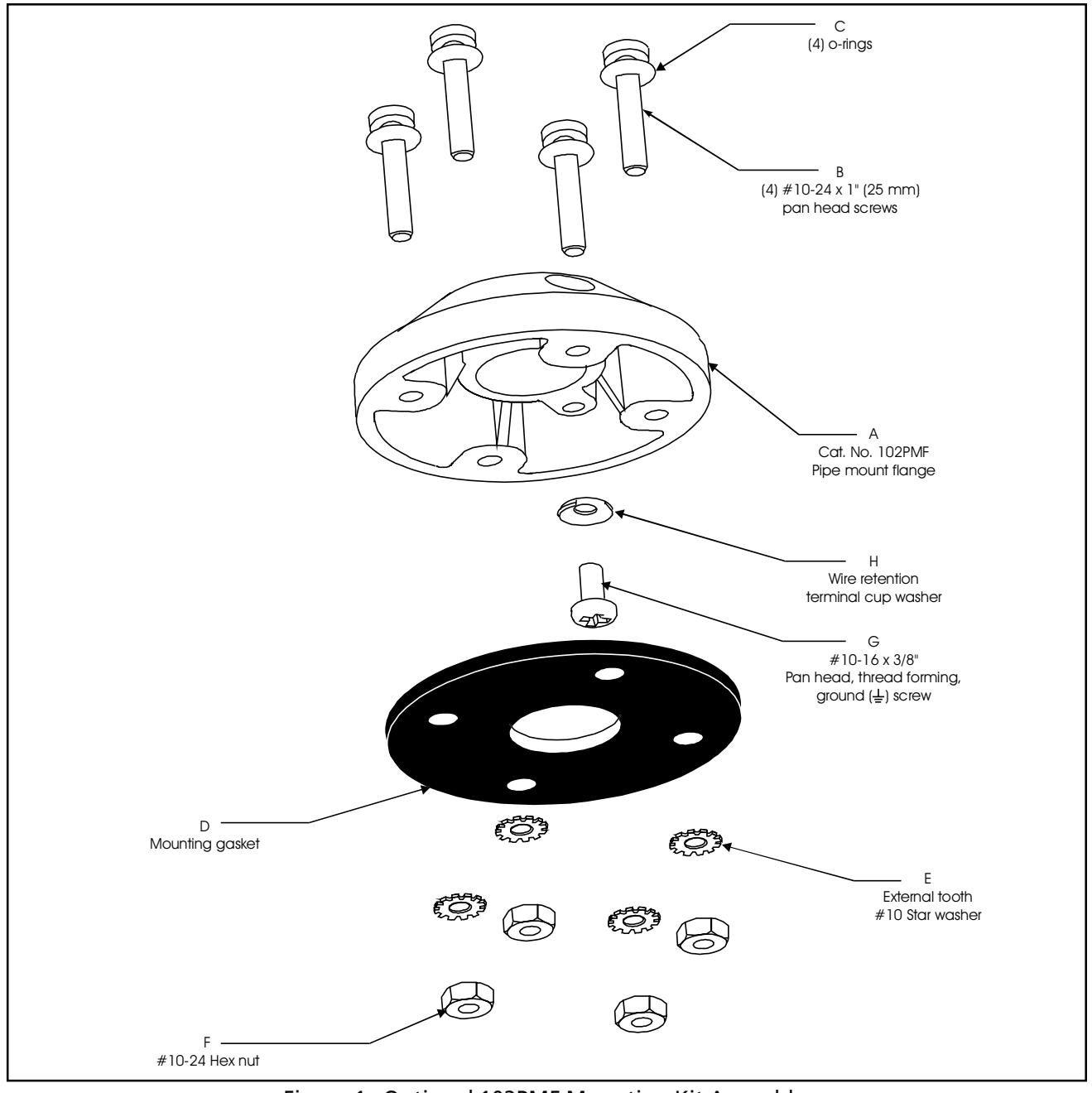
Figure 1. Optional 102PMF Mounting Kit Assembly
PAGE 7 P/N 3100179 ISSUE 1
2. A two (2) position screw terminal is provided to connect separate 24V DC light source operating power to the Chameleon DeviceNet Status Indicator. The terminals for the 24V DC unit are labeled as "+" and "-". Make connections as follows:
| Pin 1 (+) | + 24V DC | Red Wire |
|---|---|---|
| Pin 2 (-) | - 24V DC | Black Wire |
3. If it is desired to power the light sources from DeviceNet power, jumper (V+) and (V-) on the 5 position DeviceNet terminal block to (+) and (-) respectively on the 2 position screw terminal.
Set DIPSWITCH S1 for the BAUD RATE and MAC ID required as follows:
Note the legend on the dipswitch for the sense of 0 and 1 (0 = OFF and 1 = ON)
| SW1 | SW2 | SW3 | SW4 | SW5 | SW6 | SW7 | SW8 | |
|---|---|---|---|---|---|---|---|---|
| BAUD RATE - 125 Kbps | 0 | 0 | ||||||
| BAUD RATE - 250 Kbps | 0 | 1 | ||||||
| BAUD RATE - 500 Kbps | 1 | 0 | ||||||
| BAUD RATE - 125 Kbps | 1 | 1 | ||||||
| MAC ID 0 | 0 | 0 | 0 | 0 | 0 | 0 | ||
| MAC ID 1 | 0 | 0 | 0 | 0 | 0 | 1 | ||
| MAC ID 2 | 0 | 0 | 0 | 0 | 1 | 0 | ||
| MAC ID 3 | 0 | 0 | 0 | 0 | 1 | 1 | ||
| MAC ID 4 | 0 | 0 | 0 | 1 | 0 | 0 | ||
| MAC ID 5 | 0 | 0 | 0 | 1 | 0 | 1 | ||
| MAC ID 6 | 0 | 0 | 0 | 1 | 1 | 0 | ||
| MAC ID 7 | 0 | 0 | 0 | 1 | 1 | 1 | ||
| MAC ID 8 | 0 | 0 | 1 | 0 | 0 | 0 | ||
| MAC ID 9 | 0 | 0 | 1 | 0 | 0 | 1 | ||
| MAC ID 10 (0x0A) | 0 | 0 | 1 | 0 | 1 | 0 | ||
| MAC ID 11 (0x0B) | 0 | 0 | 1 | 0 | 1 | 1 | ||
| MAC ID 12 (0x0C) | 0 | 0 | 1 | 1 | 0 | 0 | ||
| MAC ID 13 (0x0D) | 0 | 0 | 1 | 1 | 0 | 1 | ||
| MAC ID 14 (0x0E) | 0 | 0 | 1 | 1 | 1 | 0 | ||
| MAC ID 15 (0x0F) | 0 | 0 | 1 | 1 | 1 | 1 | ||
| MAC ID 16 (0x10) | 0 | 1 | 0 | 0 | 0 | 0 | ||
| MAC ID 17 (0x11) | 0 | 1 | 0 | 0 | 0 | 1 | ||
| MAC ID 18 (0x12) | 0 | 1 | 0 | 0 | 1 | 0 | ||
| MAC ID 19 (0x13) | 0 | 1 | 0 | 0 | 1 | 1 | ||
| MAC ID 20 (0x14) | 0 | 11 | 0 | 11 | 0 | 0 | ||
| MAC ID 21 (0x15) | 0 | 1 | 0 | 1 | 0 | 1 | ||
| MAC ID 22 (0x16) | 0 | 1 | 0 | 1 | 1 | 0 | ||
| MAC ID 23 (0x17) | 0 | 1 | 0 | 1 | 1 | 1 | ||
| MAC ID 24 (0x18) | 0 | 1 | 1 | 0 | 0 | 0 | ||
| MAC ID 25 (0x19) | 0 | 1 | 1 | 0 | 0 | 1 | ||
| MAC ID 26 (0x1A) | 0 | 1 | 1 | 0 | 1 | 0 | ||
| MAC ID 27 (0x1B) | 0 | 1 | 1 | 0 | 1 | 1 | ||
| MAC ID 28 (0x1C) | 0 | 1 | 1 | 1 | 0 | 0 | ||
| MAC ID 29 (0x1D) | 0 | 1 | 1 | 1 | 0 | 1 | ||
| MAC ID 30 (0x1E) |
| SW1 | SW2 | SW3 | SW4 | SW5 | SW6 | SW7 | SW8 | |
|---|---|---|---|---|---|---|---|---|
| MAC ID 31 (0x1F) | 0 | 1 | 1 | 1 | 1 | 1 | ||
| MAC ID 32 (0x20) | 1 | 0 | 0 | 0 | 0 | 0 | ||
| MAC ID 33 (0x21) | 1 | 0 | 0 | 0 | 0 | 1 | ||
| MAC ID 34 (0x22) | 1 | 0 | 0 | 0 | 1 | 0 | ||
| MAC ID 35 (0x23) | 1 | 0 | 0 | 0 | 1 | 1 | ||
| MAC ID 36 (0x24) | 1 | 0 | 0 | 1 | 0 | 0 | ||
| MAC ID 37 (0x25) | 1 | 0 | 0 | 1 | 0 | 1 | ||
| MAC ID 38 (0x26) | 1 | 0 | 0 | 1 | 1 | 0 | ||
| MAC ID 39 (0x27) | 1 | 0 | 0 | 1 | 1 | 1 | ||
| MAC ID 40 (0x28) | 1 | 0 | 1 | 0 | 0 | 0 | ||
| MAC ID 41 (0x29) | 1 | 0 | 1 | 0 | 0 | 1 | ||
| MAC ID 42 (0x2A) | 1 | 0 | 1 | 0 | 1 | 0 | ||
| MAC ID 43 (0x2B) | 1 | 0 | 1 | 0 | 1 | 1 | ||
| MAC ID 44 (0x2C) | 1 | 0 | 1 | 1 | 0 | 0 | ||
| MAC ID 45 (0x2D) | 1 | 0 | 1 | 1 | 0 | 1 | ||
| MAC ID 46 (0x2E) | 1 | 0 | 1 | 1 | 1 | 0 | ||
| MAC ID 47 (0x2F) | 1 | 0 | 1 | 1 | 1 | 1 | ||
| MAC ID 48 (0x30) | 1 | 1 | 0 | 0 | 0 | 0 | ||
| MAC ID 49 (0x31) | 1 | 1 | 0 | 0 | 0 | 1 | ||
| MAC ID 50 (0x32) | 1 | 1 | 0 | 0 | 1 | 0 | ||
| MAC ID 51 (0x33) | 1 | 1 | 0 | 0 | 1 | 1 | ||
| MAC ID 52 (0x34) | 1 | 1 | 0 | 1 | 0 | 0 | ||
| MAC ID 53 (0x35) | 1 | 1 | 0 | 1 | 0 | 1 | ||
| MAC ID 54 (0x36) | 1 | 1 | 0 | 1 | 1 | 0 | ||
| MAC ID 55 (0x37) | 1 | 1 | 0 | 1 | 1 | 1 | ||
| MAC ID 56 (0x38) | 1 | 1 | 1 | 0 | 0 | 0 | ||
| MAC ID 57 (0x39) | 1 | 1 | 1 | 0 | 0 | 1 | ||
| MAC ID 58 (0x3A) | 1 | 1 | 1 | 0 | 1 | 0 | ||
| MAC ID 59 (0x3B) | 1 | 1 | 1 | 0 | 1 | 1 | ||
| MAC ID 60 (0x3C) | 1 | 1 | 1 | 1 | 0 | 0 | ||
| MAC ID 61 (0x3D) | 1 | 1 | 1 | 1 | 0 | 1 | ||
| MAC ID 62 (0x3E) | 1 | 1 | 1 | 1 | 1 | 0 | ||
| MAC ID 63 (0x3F) | 1 | 1 | 1 | 1 | 1 | 1 |
4. Connect the five position female connector on the tone module to the upper set of male pins in the Chameleon DeviceNet Status Indicator. Set the selected tone in accordance with the table below. Set the third Byte (Data Byte 2) in accordance with the table below in order to access the required tone. "X" is the "Don't Care" State.
| Switch | n Settings* | |||
|---|---|---|---|---|
| Tone | Bit3 | Bit2 | Bit1 | Bit0 |
| Tone Off | 0 | Х | Х | Х |
| Stutter Beep | 1 | 0 | 0 | 0 |
| Continuous | 1 | 0 | 0 | 1 |
| 3 Pulse Horn | 1 | 0 | 1 | 0 |
| Rapid Siren | 1 | 0 | 1 | 1 |
| Hi/Lo | 1 | 1 | 0 | 0 |
| Fast Whoop | 1 | 1 | 0 | 1 |
| Yeow | 1 | 1 | 1 | 0 |
| Веер | 1 | 1 | 1 | 1 |
*1 is ON. 0 is OFF.
PAGE 9
- 5. Install the front cover or the optional multi-tone module by tightening the two captive front screws.
- 6. Test the Chameleon DeviceNet Status Indicator to ensure that it operates as intended.
To test the device for functionality the unit must be connected to a DeviceNet network via the five (5) pin connector. Turn on the network power supply and local power (if so configured) for the lamps. All lamps will flash instantaneously (some lamps may not be visible) as the unit checks for proper lamp operation. The value of the data byte in the master poll will be displayed on the lamps until it is changed by subsequent poll command. The pre-defined poll connection has consume size of three (3) bytes, and a produce size of three (3) bytes. When all the connections are released the lamps will display the last poll command data before release of the connection.
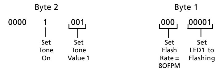
7. The following is an Output Data Byte example
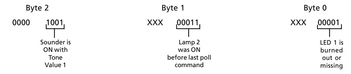
8. The following is an Input Data Byte example:
Maintenance
The lens surfaces should be periodically dusted and cleaned with a dry soft clean cloth to maintain optimum light visibility. If necessary, the outside of the lens may be cleaned with water and a mild detergent on a well rung out soft clean cloth.
Table 1. Chameleon DeviceNet Status Indicator Specifications
| Catalog No. |
Electrical
Ratings |
Lamp Life
(Hours) |
|---|---|---|
|
108-DN-RGA-G1
108-DN-RBA-G1 |
24V DC, 0.105 A | 100,000 |
|
108-DN-RGA-N5
108-DN-RBA-N5 |
120V AC, 0.12A | 100,000 |
Table 2. Pertinent DeviceNet Specifications
| Operating DeviceNet Bus Current | 0.12A |
|---|---|
| Current Draw supplied by separate power supply (per Light Module) | DC: 0.062 to 0.320A |
| AC: 0.022 to 0.120A | |
| In-Rush Current supplied by separate power supply (per Light Module) | DC: 1.2A |
| AC: 0.5A | |
| Flash Rate (selectable via second data byte of POLL command) | 45, 60 or 80 fpm |
| Operating Temperature | 32F to 158F (0C to 70C) |
Contacting Edwards:
Phone: (203) 699-3000
E-Mail: techsupport@edwards-signals.com
customerservice@edwards-signals.com
Website: http://www.edwards-signals.com