Edwards Signaling 107DV2ST Series Installation Instructions
Open the original PDF document
View PDFInstallation Instructions for 107DV2 Series AdaptaBeacon® Strobe Light for Use in Hazardous Locations
Description
The 107DV2 Series AdaptaBeacon strobe signaling appliances are intended for general utility signaling use. They are available in pendant, bracket or ceiling mount configurations and in 12-48V DC, 250V DC, 120V 60 Hz and 240V 60 Hz. They are UL and cUL Listed for use in Class I, Division 2, Group A, B, C and D hazardous locations; pendant-mount versions with clear globes are also listed for Class II, Division 1, Group E, F and G, Class II, Division 2, Group F and G, and Class III Division 1 and 2 hazardous locations. Operating Temperature Codes are per the following chart.
Operating Temperature Codes
NOTE: Class II and Class III only apply to Pendant Mount with clear globes
|
Class II, Div. 2,
Groups F, G; Class III, Div. 2 |
||
|---|---|---|
|
Ambient
Temp. |
Class I, Div. 2
Groups A, B, C, D |
Class II, Div. 1,
Groups E, F, G; Class III, Div. 1 |
| 40°C | 300°C (T2) | 120°C (T4A) |
| 55°C | 450°C (T1) | 135°C (T4) |
| 65°C | 450°C (T1) | 160°C (T3C) |
They are UL and cUL listed as Type 3R and 4. AC rated strobes are also UL and cUL listed for Marine.
The strobe flashes a 360-degree beam of light approximately 65 times per minute.
Installation

WARNING
To reduce the risks of ignition of hazardous atmospheres and shock, do not apply power to the unit until installation has been completed and unit is tightly assembled and secured.
Install this unit in accordance with the applicable requirements in the latest edition of the National Electrical Code or Canadian Electrical Code, using supply wire rated per Table 2.
1. Pendant Mount Models (Figure 1): Install explosion-proof hanger box (not supplied). Pull the unit's wire leads through the 3/4" (19 mm) NPT threaded conduit (not supplied). Secure the 3/4" (19 mm) threaded conduit to the mounting hood.
Ground the unit in accordance with National Electrical Code (NFPA 70) and local requirements.
Connect red positive (+) wire lead to incoming positive (+) and connect black negative (-) wire lead to incoming negative using wire nuts (not supplied).
Secure the 3/4" (19 mm) threaded conduit to the outlet box.
2. Bracket Mount Models (Figure 2): Remove the outlet box from the end of the mounting bracket. Install the outlet box using appropriate hardware (not
supplied) for the mounting surface. Pull the field wiring through the outlet box.
Ground the unit in accordance with National Electrical Code (NFPA 70) and local requirements.
Connect red positive (+) wire lead to incoming positive (+) and connect black negative (-) wire lead to incoming negative using wire nuts (not supplied).
Mount the wall bracket back onto the outlet box.
3. Ceiling Mount Installation (Figures 3 and 4): Unscrew and remove the clear outer globe. Remove the two screws holding the circuit assembly to the bottom of the fixture. To separate the ceiling junction box from the fixture housing, remove the remaining two screws at the bottom of the fixture.
Mount the ceiling junction box using appropriate hardware. Pull power source wiring through the ceiling junction box.
Ground the unit in accordance with National Electrical Code (NFPA 70) and local requirements.
Connect the positive (+) power source wire to the positive (+) terminal and the negative (-) power source wire to the negative (-) terminal.
Secure the fixture housing on the junction box by replacing the two screws removed above. Reinstall the circuit assembly to the bottom of the fixture using the two screws removed above.
Screw the clear outer globe back on the fixture housing.
4. Where applicable, install the optional guard assembly over the clear outer globe and secure using three screws (provided).
A
WARNING
To reduce the risk of ignition of hazardous atmospheres and shock, keep assembly tightly closed when circuits are energized.
5. Apply power to the unit and ensure proper function.
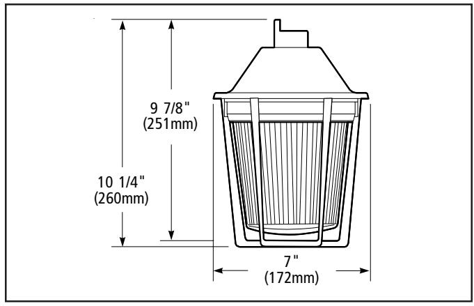
Figure 1. Detail of Pendant Mounting
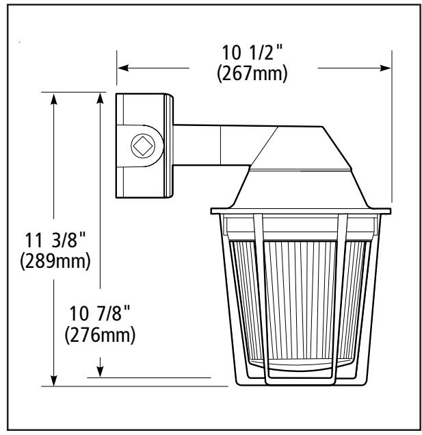
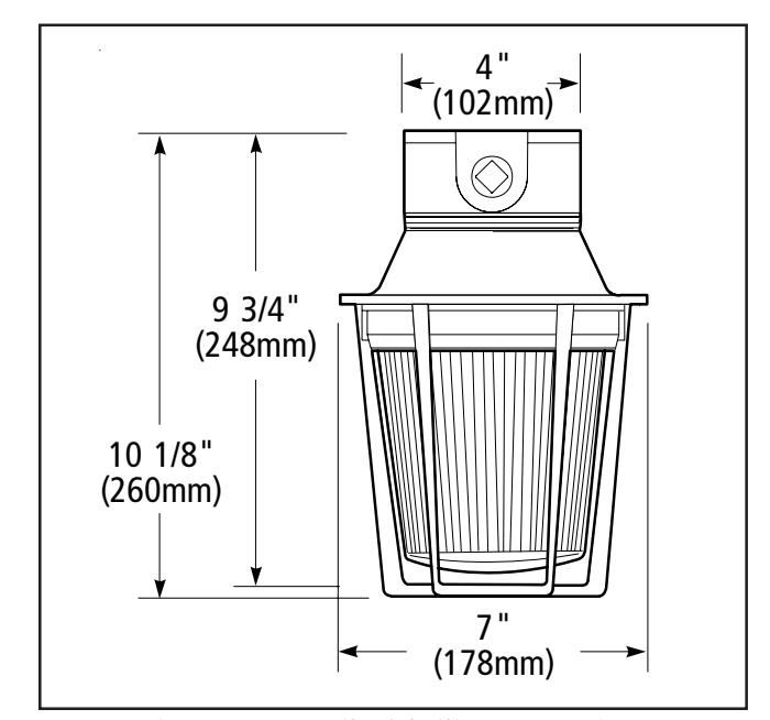
Figure 2. Detail of Bracket Mounting Figure 3. Detail of Ceiling Mounting
Maintenance

WARNING
To reduce the risk of ignition of hazardous atmospheres and shock, keep assembly tightly closed when circuits are energized.
To reduce the risk of ignition of hazardous atmospheres and shock, disconnect from the supply and circuit and allow five (5) minutes for stored energy to dissipate before disassembling the unit.
Disassemble the unit as follows (Figure 4):
1. Where applicable, remove the guard by rotating counterclockwise.
- 2. Unscrew and remove the clear outer globe.
- 3. To replace the strobe tube, remove the inner lens and replace the appropriate tube as listed in Table 1.
- 4. Reinstall the inner lens. Screw the clear outer globe back onto the fixture housing.
- 5. Where applicable, install the guard assembly over the clear outer globe by rotating clockwise until it snaps into place.
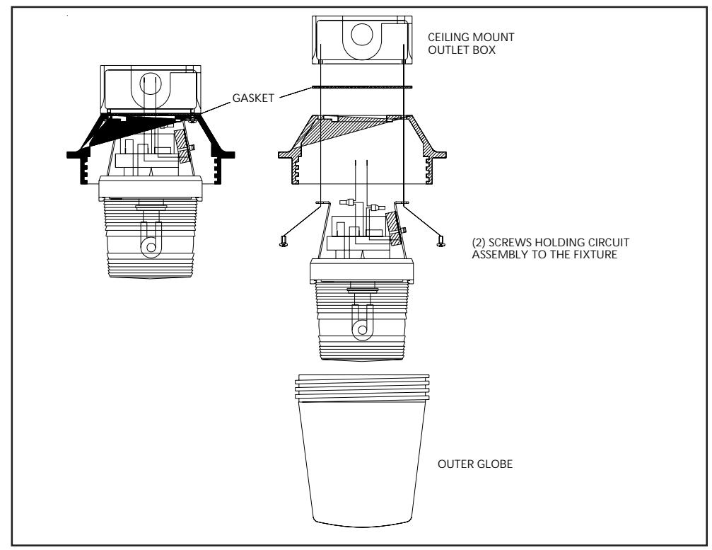
Figure 4. Disassembly of the 107DV2 Series Adaptabeacons
Table 1. 107DV2 Series AdaptaBeacon Strobes
| Catalog Number |
Mounting
Method |
Voltage | Current |
Conduit
Size |
Flash
Rate |
Strobe Tube
Replacement |
|---|---|---|---|---|---|---|
| 107DV2PST*-N5 | Pendant | 120V 60 Hz | 0.1A | 3/4" NPT | Approx. | 92-ST |
| 107DV2BST*-N5 | Bracket | 65 fpm | ||||
| 107DV2CST*-N5 | Ceiling | |||||
| 107DV2PST*-R5 | Pendant | 240V 60 Hz | 0.05A | 3/4" NPT | Approx. | 92-ST |
| 107DV2BST*-R5 | Bracket | 65 fpm | ||||
| 107DV2BST*-R5 | Ceiling | |||||
| 107DV2PST*-EK | Pendant | 12-48V DC | 1.2-0.38A | 3/4" NPT | Approx. | 92-ST |
| 107DV2BST*-EK | Bracket | 65 fpm | ||||
| 107DV2CST*-EK | Ceiling | |||||
| 107DV2PST*-S1 | Pendant | 250V DC | 0.1A | 3/4" NPT | Approx. | 92-ST |
| 107DV2BST*-S1 | Bracket | 65 fpm | ||||
| 107DV2BST*-S1 | Ceiling |
* Letter in this position denotes color of the globe: A - amber, B - blue, C - clear, G - green, R - red or M - magenta
Table 2. Supply Wire Temperature Markings
|
Ambient
Temperature |
Supply Wire
Temperature Marking |
|||
|---|---|---|---|---|
| 40°C | 60°C | |||
| 55°C | 75°C | |||
| 65°C | 90°C | |||
Contacting Edwards:
Phone: (203) 699-3000
E-Mail: techsupport@edwards-signals.com
customerservice@edwards-signals.com
Website: http://www.edwards-signals.com