Edwards Signaling 106DEXSTC-FJ Series Installation Instructions
Open the original PDF document
View PDF

Installation Instructions for 106DEXST-FJ AdaptaBeacon® Strobe Lights for Use in Hazardous Locations
Description
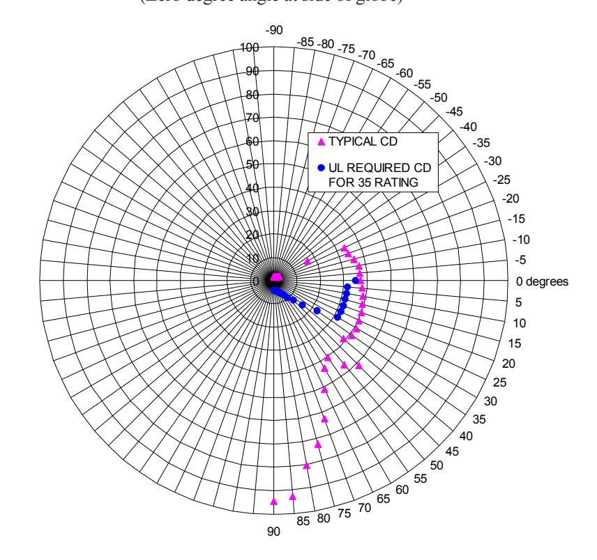
The 106DEXSTC-FJ (clear lens only) AdaptaBeacons are inrush current limited strobe lights that are UL1971 listed as Special Application 20-30V DC Signaling Appliances for the Hearing Impaired, with CSFM Listing as well. They are intended for indoor use in UL listed compatible fire alarm systems and other applications requiring electrical supervision of signaling circuit field wiring. The strobe flashes a 360-degree beam of light approximately 65 times per minute with a 55 cd ceiling light output (35 cd other) per Figure 5.
When assembled in accordance with these instructions, these 106DEX Series visual strobe signals are UL listed for use in Class I, Division 1, Group C and D, Class I, Division 2, Group A, B, C and D, Class II, Division 1, Group E, F and G, Class II, Division 2, Group F and G, and Class III Division 1 and 2 hazardous locations with Operating Temperature Codes per the following chart.
Operating Temperature Codes
|
Class I, Div. 2,
Groups C and D |
Class II, Div. 2,
Groups F, G; Class III, Div. 2 |
||
|---|---|---|---|
| Ambient | Class I, Div. 2 | Class I, Div. 1 |
Class II, Div. 1,
Groups E, F, G; |
| Temp. | Groups A and B | Groups C and D | Class III, Div. 1 |
| 40°C | 260°C (T2B) | 85°C (T6) | 120°C (T4A) |
| 55°C | 280°C (T2A) | 100°C (T5) | 135°C (T4) |
| 65°C | 280°C (T2A) | 120°C (T4A) | 160°C (T3C) |
Installation
Install this unit in accordance with the applicable requirements in the latest edition of the National Electrical Code.

WARNING
To reduce the risk of ignition of hazardous atmospheres and shock, do not apply power to the unit until installation has been completed and unit is tightly assembled and secured.
NOTE: This unit must be mounted vertically with the globe assembly vertically facing down in Hearing Impaired Applications.
-
1. Mount using the following applicable method.
- a. Pendant Mount Models (Figures 1 and 4): Unscrew the globe assembly from the mounting hood and set aside. Install explosion-proof hanger
- box (not supplied). Secure 3/4" (19 mm) NPT threaded conduit (not supplied) to the box. Install the hood on the conduit. Proceed to step 2.
- b. Ceiling Mount Models (Figures 2 and 4): Unscrew the globe assembly from the ceiling mount box. Mount the ceiling box using appropriate hardware (not supplied) suitable for the mounting surface. Proceed to step 2.
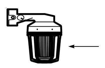
- c. Bracket Mount Models (Figures 3 and 4): Unscrew the globe assembly from the wall bracket. Install the mounting bracket using appropriate hardware (not supplied) for the mounting surface. Pull the field wiring through the mounting bracket. Proceed to step 2.
- 2. Extend the required power source wiring down through the mounting hood. See Table 4 for required supply wire temperature ratings.
- 3. A ground screw is provided in the wiring compartment for attachment of field earth ground wire.
- 4. Connect the two red positive (+) and two black negative (-) wire leads to the supervised circuit in accordance with Figure 4.
- 5. Install the fixture on the mounting hood, bracket or box as applicable.

WARNING
To reduce the risk of ignition of hazardous atmospheres and shock, keep assembly tightly closed when circuits are energized.
6. Apply power to the unit and ensure proper function.
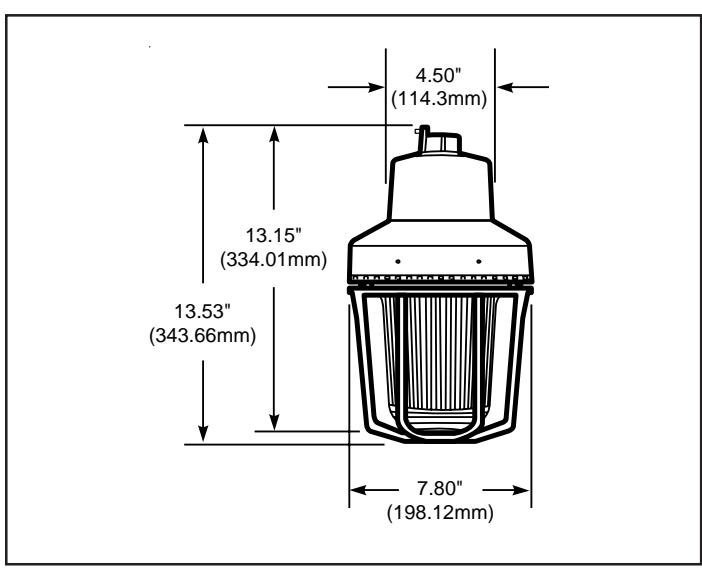
Figure 1. Detail of Pendant Mounting
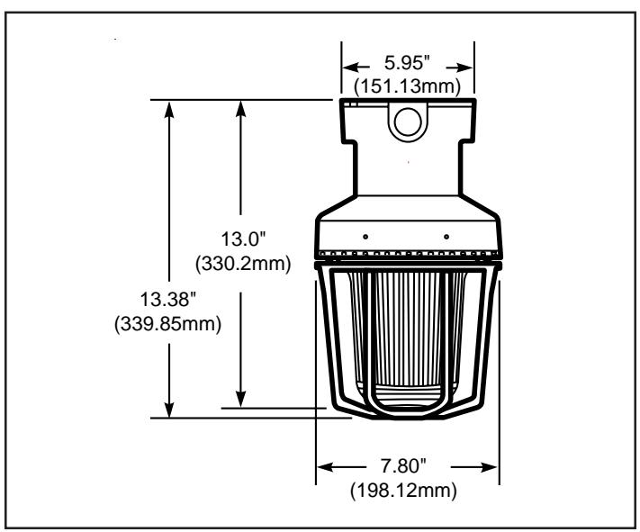
Figure 2. Detail of Ceiling Mounting
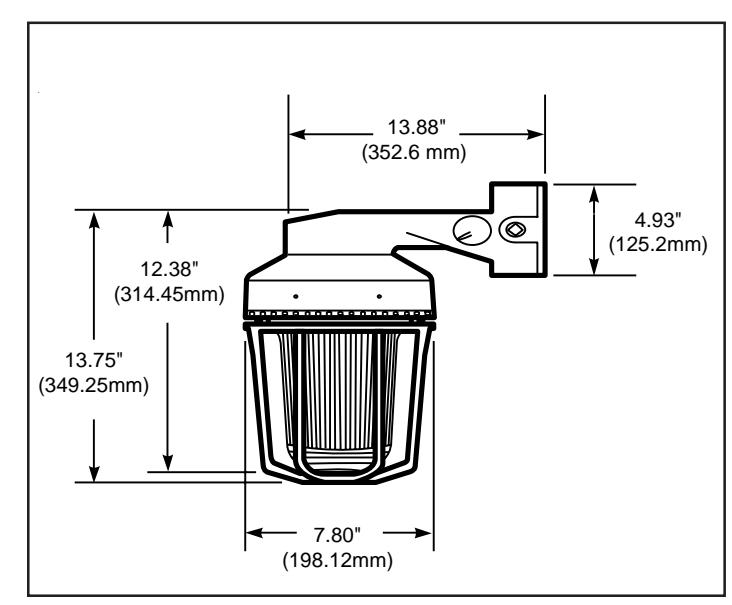
Figure 3. Detail of Bracket Mounting
Maintenance

WARNING
To reduce the risk of ignition of hazardous atmospheres and shock, keep assembly tightly closed when circuits are energized.
To reduce the risk of ignition of hazardous atmospheres and shock, disconnect from the supply and circuit and allow five (5) minutes for stored energy to dissipate before disassembling the unit.
For strobe tube replacement, disconnect from the supply circuit and allow five (5) minutes for stored energy to dissipate before starting work or disassembly (Figure 6).
- 1. Loosen the (3) guard screws and remove the guard.
- 2. Loosen the globe and ring assembly set screw. Insert a suitable tool into the notches in the globe and ring assembly and loosen the assembly by prying in a counterclockwise direction. Remove the ring and globe assembly.
A
CAUTION
When replacing the strobe tube, do not handle the tube. Hold the strobe tube only by its base to prevent damage to the tube.
- Refer to Table 2 for the correct replacement catalog number and replace the necessary part.
- 4. To replace, simply screw the unit on until it seats firmly onto its gasket. Tighten the unit another 1/8 to 1/4 turn. Tighten the setscrew.
- 5. Reinstall the guard, where applicable, and secure using the three supplied screws.
- 6. After the unit is assembled, apply power and make sure the unit functions properly.
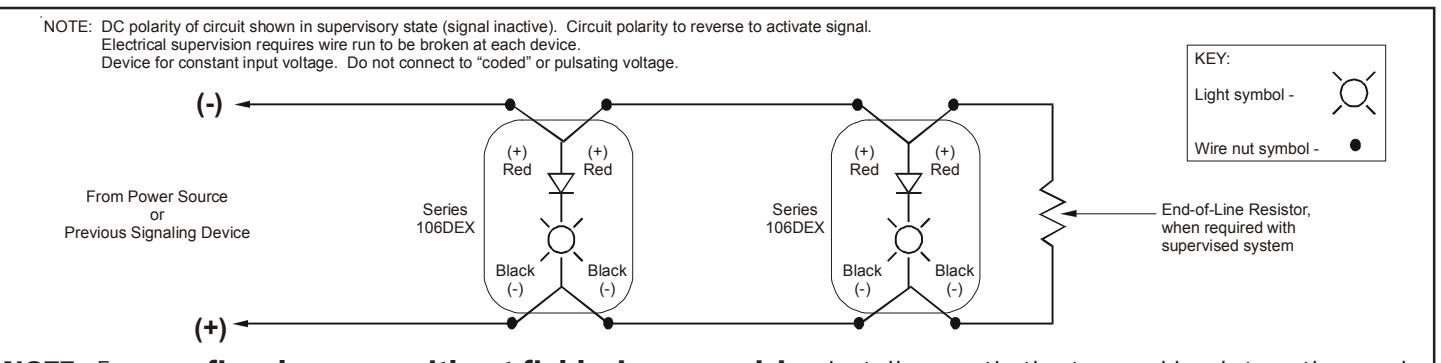
NOTE: For non-fire alarm use without field wire supervision installer can tie the two red leads together and tie the two black leads together.
Figure 4. Wiring Diagram
Table 1. 106DEX AdaptaBeacon Strobe Light Electrical Specifications
| Operating Current* | Initial Surge Inrush Current | Repetitive Surge Current | ||||
|---|---|---|---|---|---|---|
| Voltage** RMS Current (A) | Mean Current (A) | Current (A) | Time (mS) | Current (A) | Time (mS) | |
| 20V DC | 1.08 | 0.84 | 2.70 | 1.10 | 2.24 | 450 |
| 24V DC | 0.95 | 0.69 | 2.97 | 1.13 | 2.21 | 400 |
| 28V DC | 0.85 | 0.66 | 3.06 | 1.24 | 2.16 | 381 |
| 30V DC | 0.83 | 0.64 | 3.14 | 1.27 | 2.14 | 360 |
* Use the operating current to establish the wire gauge and standby power requirements. Consult the control unit manufacturer to determine surge and peak current effects and maximum number of strobes on the system.
Table 2. 106DEX AdaptaBeacon Strobe Light Specifications
| Cat. No. |
Mounting
Method |
Conduit
Size |
Flash
Rate |
Rated Light
Output |
|---|---|---|---|---|
| 106DEXPSTC-FJ | Pendant | 3/4" | 360° beam | 55 cd/35 cd |
| Figure 1 | NPT | of light at | per | |
| 106DEXCSTC-FJ | Ceiling | ~65 fpm | Figure 5 | |
| Figure 2 | ||||
| 106DEXBSTC-FJ | Bracket | |||
| Figure 3 |
Table 3. 106DEX AdaptaBeacon Strobe Light Replacement Parts
| Cat. No. |
Mounting
Method |
Replacement
Strobe |
|---|---|---|
| 106DEXPSTC-FJ |
Pendant
Figure 1 |
Cat. No.
92-ST |
| 106DEXCSTC-FJ |
Ceiling
Figure 2 |
|
| 106DEXBSTC-FJ |
Bracket
Figure 3 |
Table 4. Supply Wire Temperature Markings
|
Ambient
Temperature |
Supply Wire
Temperature Marking |
|---|---|
| 40°C | 75°C |
| 55°C | 90°C |
| 65°C | 105°C |
** CAUTION: To prevent damage to the visual signal's internal circuit and to assure its continued proper functioning, DO NOT operate the unit outside of the Special Application Voltage range of 20-30V DC.
| WALL | UL1971 REQUIRED | |
| BRACKET | DISPERSION AS % OF CD | |
| MOUNTING | RATING | |
| ANGLE | VERTICAL | HORIZONTAL |
| (DEGREES) | PLANE | PLANE |
| zero | 100% | 100% |
| 5 | 90% | 90% |
| 10 | 90% | 90% |
| 15 | 90% | 90% |
| 20 | 90% | 90% |
| 25 | 90% | 90% |
| 30 | 90% | 75% |
| 35 | 65% | 75% |
| 40 | 46% | 75% |
| 45 | 34% | 75% |
| 50 | 27% | 55% |
| 55 | 22% | 45% |
| 60 | 18% | 40% |
| 65 | 16% | 35% |
| 70 | 15% | 35% |
| 75 | 13% | 30% |
| 80 | 12% | 30% |
| 85 | 12% | 25% |
| 90 | 12% | 25% |
|
Compound
45 |
24% | |

(Zero degree angle at side of globe)
UL 1971 Hearing Impaired: 35 cd wall UL 1638 General Utility: 35 cd at 0o axis
|
UL1971
CEILING REQUIRED MOUNTING X & Y PLANE DISPERSION AS % OF CD ANGLE RATING |
Effective Candela Light Output for Ceiling Mount
X & Y Planes (Zero degree angle at bottom of of globe) |
|---|---|
|
(DEGREES)
0 100% 5 90% 10 90% 15 90% 20 90% 25 90% 30 75% 35 75% 40 75% 45 75% 50 55% 55 45% 60 40% 65 35% 70 35% 75 30% 80 30% 85 25% 90 25% Compound 45 24% |
180
175 170 170 165 165 100 160 160 155 155 150 150 90 145 145 140 80 140 135 135 70 130 130 125 125 60 TYPICAL CD 120 120 50 UL REQUIRED CD 95 100 105 110 115 115 FOR 55 RATING 40 110 30 105 20 100 10 95 90 0 90 85 85 65 70 75 80 80 75 70 65 60 60 55 55 50 50 45 45 40 40 35 35 30 30 25 25 20 20 15 15 10 10 5 5 |
|
UL 1971 Hearing Impaired: 55 cd ceiling
UL 1638 General Utility: 94 cd at 0o axis |
degrees 0 |
Figure 5. Light Output Patterns for 105DHISTC-FJ (Unit with clear lens only)
UL 1638 General Utility: 94 cd at 0o
axis
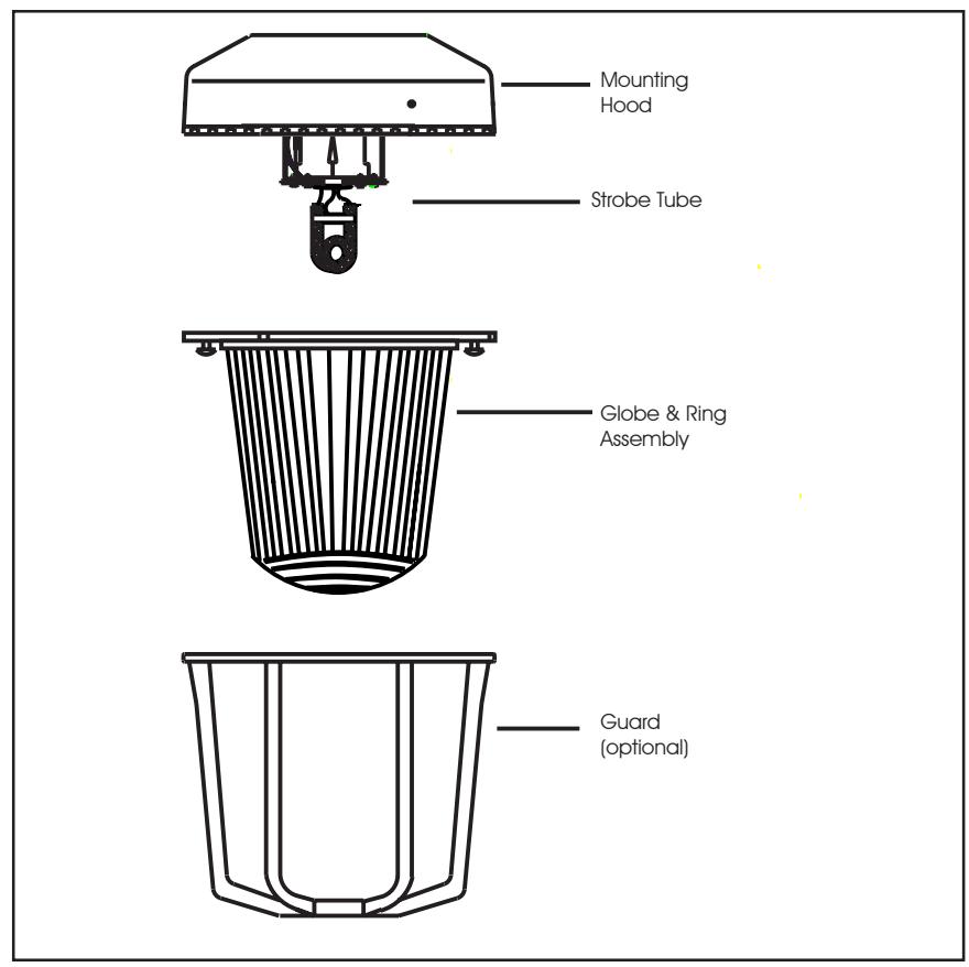
Figure 6. Disassembly of the 106DEX Series AdaptaBeacons
Contacting Edwards:
Phone: (203) 699-3000
E-Mail: techsupport@edwards-signals.com
customerservice@edwards-signals.com
Website: http://www.edwards-signals.com