Edwards Signaling 106DEXRINH-GW Series Installation Instructions
Open the original PDF document
View PDF

Installation Instructions for 106DEX AdaptaBeacon® Field Wiring Supervisable DC Rotating Lights for Use in Hazardous Locations
Description
The 106DEX AdaptaBeacon 24-28V DC rotating signaling appliances are heavy duty diode-polarized rotating lights intended for use in general utility signaling (non-fire alarm) applications requiring electrical supervision of signaling circuit field wiring. The rotating assembly motor driven at approximately 60 rpm. These devices are UL and cUL listed for use in Class I, Division 1, Group C and D, Class I, Division 2, Group C and D, Class II, Divisions 1 and 2, Group F and G, Class II, Division 1, Group E, and Class III, Division 1 and 2 hazardous locations with Operating Temperature Codes per the following chart.
Operating Temperature Codes
|
Class II, Div. 2,
Groups F, G; Class III, Div. 2 |
||
| Class II, Div. 1, | ||
| Ambient | Class I, Div. 1 & 2 | Groups E, F, G; |
| Temp. | Groups C, D | Class III, Div. 1 |
| 40°C | 85°C (T6) | 120°C (T4A) |
| 55°C | 100°C (T5) | 135°C (T4) |
| 65°C | 120°C (T4A) | 135°C (T4) |
They are UL and cUL Listed as Type 3R, 4X, and Marine enclosures.
Installation

WARNING
To reduce the risk of ignition of hazardous atmospheres and shock, do not apply power to the unit until installation has been completed and unit is tightly assembled and secured.
Install this unit in accordance with the applicable requirements in the latest edition of the National Electrical Code and Canadian Electrical Code.
NOTE: This unit must be mounted with the globe vertically facing up or down.
-
1. Mount using the following applicable method.
- a. Pendant Mount Models (Figures 1 and 5): Unscrew the globe assembly from the mounting hood and set aside. Install explosion-proof hanger box (not supplied). Secure 3/4" (19 mm) NPT threaded conduit (not supplied) to the box. Install the hood on the conduit. Proceed to step 2.
- b. Ceiling Mount Models (Figures 2 and 5): Unscrew the globe assembly from the ceiling mount box. Mount the ceiling box using appropriate hardware (not supplied) suitable for the mounting surface. Proceed to step 2.
- c. Bracket Mount Models (Figures 3 and 5): Unscrew the globe assembly from the wall bracket. Install the mounting bracket using appropriate hardware (not supplied) for the mounting surface. Pull the field wiring through the mounting bracket. Proceed to step 2.
- 2. Extend the required power source wiring down through the mounting hood. See Table 2 for required supply wire temperature ratings.
- Refer to Figure 5. Loosen the (2) screws holding the circuit block in place. Rotate and remove the circuit block.
- 4. Connect field earth ground wire to ground screw (Figure 5) or earth ground via conduit system.
- 5. Wire in accordance with Figures 4 and 5. The positive (+) terminal is gold colored and the negative (-) terminal is silver colored.
- 6. Replace circuit block and tighten two screws to hold in place.
- 7. Install the fixture on the mounting hood, bracket or box as applicable.

WARNING
To reduce the risk of ignition of hazardous atmospheres and shock, keep assembly tightly closed when circuits are energized.
8. Apply power to the unit and ensure proper function.
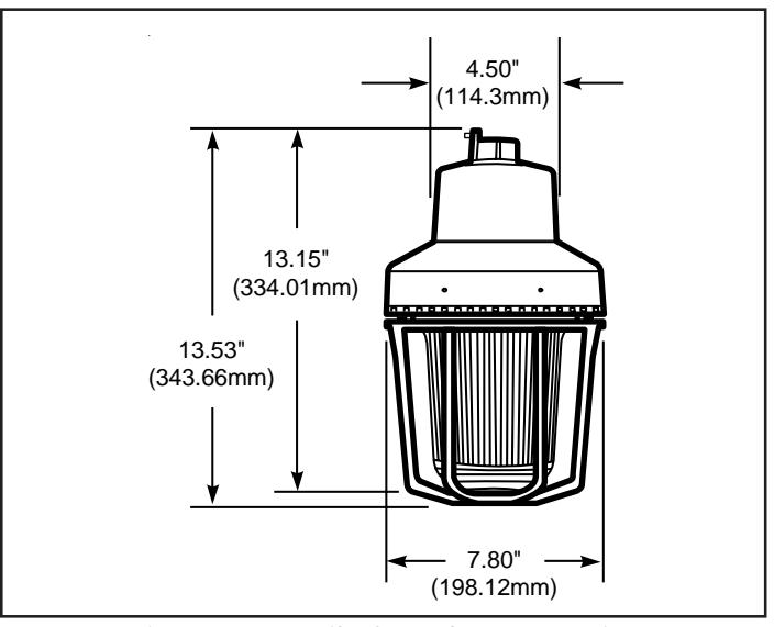
Figure 1. Detail of Pendant Mounting
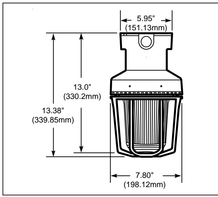
Figure 2. Detail of Ceiling Mounting
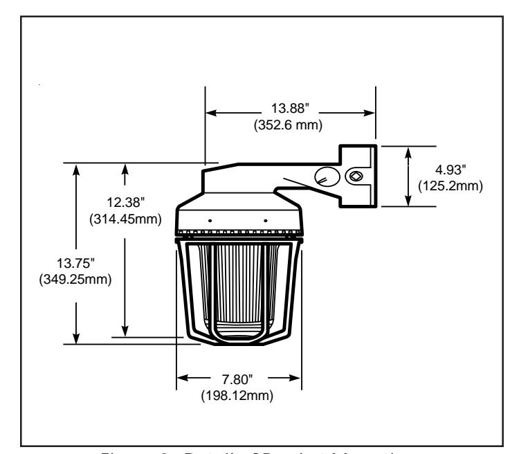
Figure 3. Detail of Bracket Mounting
Maintenance
Disassemble the unit as follows (Figure 6):
1. Loosen the (3) guard screws and remove the guard.
A
WARNING
To reduce the risk of ignition of hazardous atmospheres and shock, keep assembly tightly closed when circuits are energized.
Loosen the globe and ring assembly set screw. Insert a suitable tool into the notches in the globe and ring assembly and loosen the assembly by prying in a counterclockwise direction. Remove the ring and globe assembly.
- 3. Refer to Table 1 for the correct replacement catalog number and replace the necessary part.
- 4. To replace, simply screw the unit on until it seats firmly onto its gasket. Tighten the unit another 1/8 to 1/4 turn. Tighten the setscrew.
- Reinstall the guard, where applicable, and secure using the three supplied screws.
- 6. After the unit is assembled, apply power and make sure the unit functions properly.
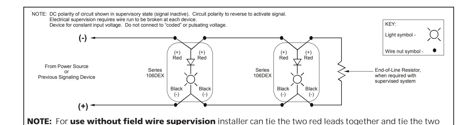
Figure 4. Wiring Diagram
black leads together.
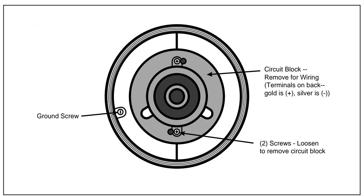
Figure 5. Wiring the AdaptaBeacon
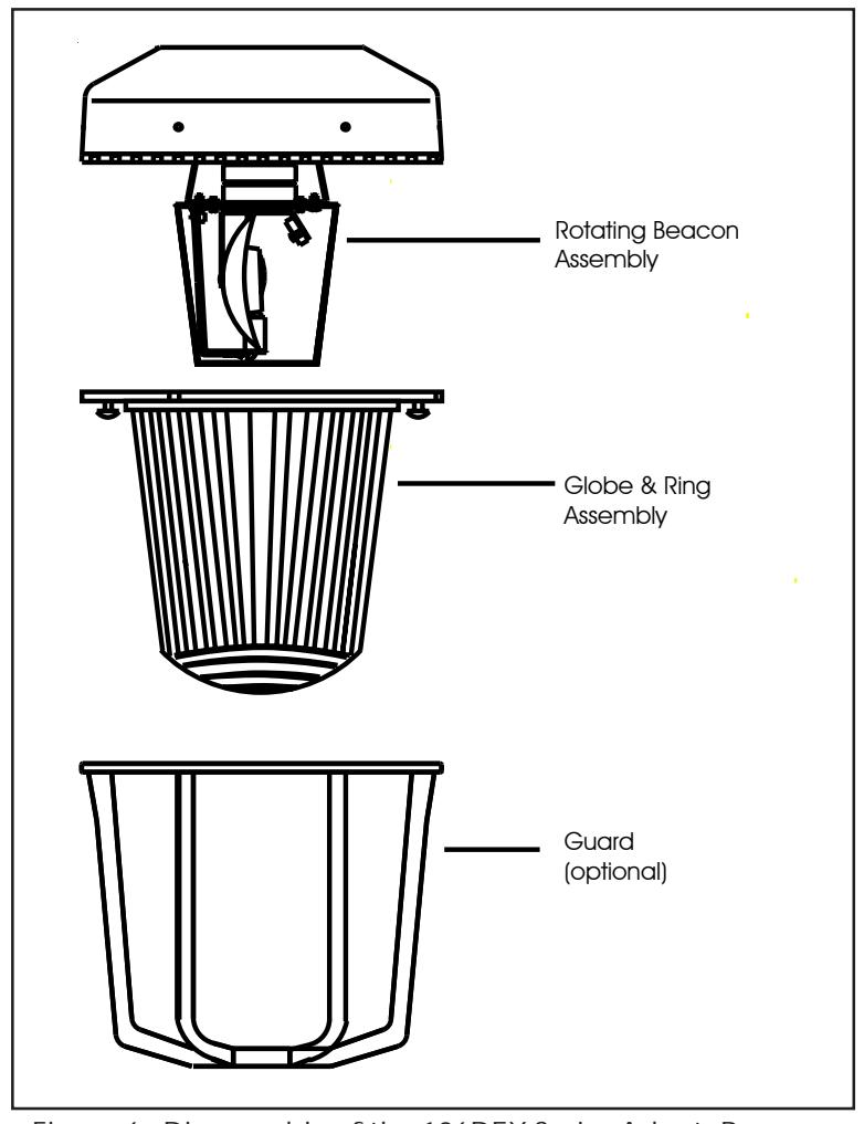
Figure 6. Disassembly of the 106DEX Series AdaptaBeacons
Table 1. 106DEX Series AdaptaBeacon Rotating Lights
| Catalog Number |
Mounting
Method |
Electrical
Ratings |
Conduit
Size |
Reflector
Rotation |
Lamp
Replacement |
|---|---|---|---|---|---|
| 106DEXPRINH*-GW | Pendant | 24 - 28V DC | 3/4" NPT | Approx. | 50LMP-20WH |
| 106DEXBRINH*-GW | Bracket | 0.8A | 60 rpm | ||
| 106DEXCRINH*-GW | Ceiling |
* Letter in this position denotes color of the globe: A - amber, B - blue, C - clear, G - green, R - red or M - magenta
Table 2. Supply Wire Temperature Markings
|
Ambient
Temperature |
Supply Wire
Temperature Marking |
||
|---|---|---|---|
| 40°C | 75°C | ||
| 55°C | 90°C | ||
| 65°C | 105°C | ||
Contacting Edwards:
Phone: (203) 699-3000
E-Mail: techsupport@edwards-signals.com
customerservice@edwards-signals.com
Website: http://www.edwards-signals.com
P/N 3100098 ISSUE 2