Edwards Signaling 101 Series Installation Instructions
Open the original PDF document
View PDF

Installation Instructions for Edwards AdaptaLight™ Heavy Duty Industrial Stackable Beacons
Cheshire, CT 06410 203-699-3300 (Ph) 203-699-3365 (Cust. Serv. Fax) 203-699-3078 (Tech. Serv. Fax)
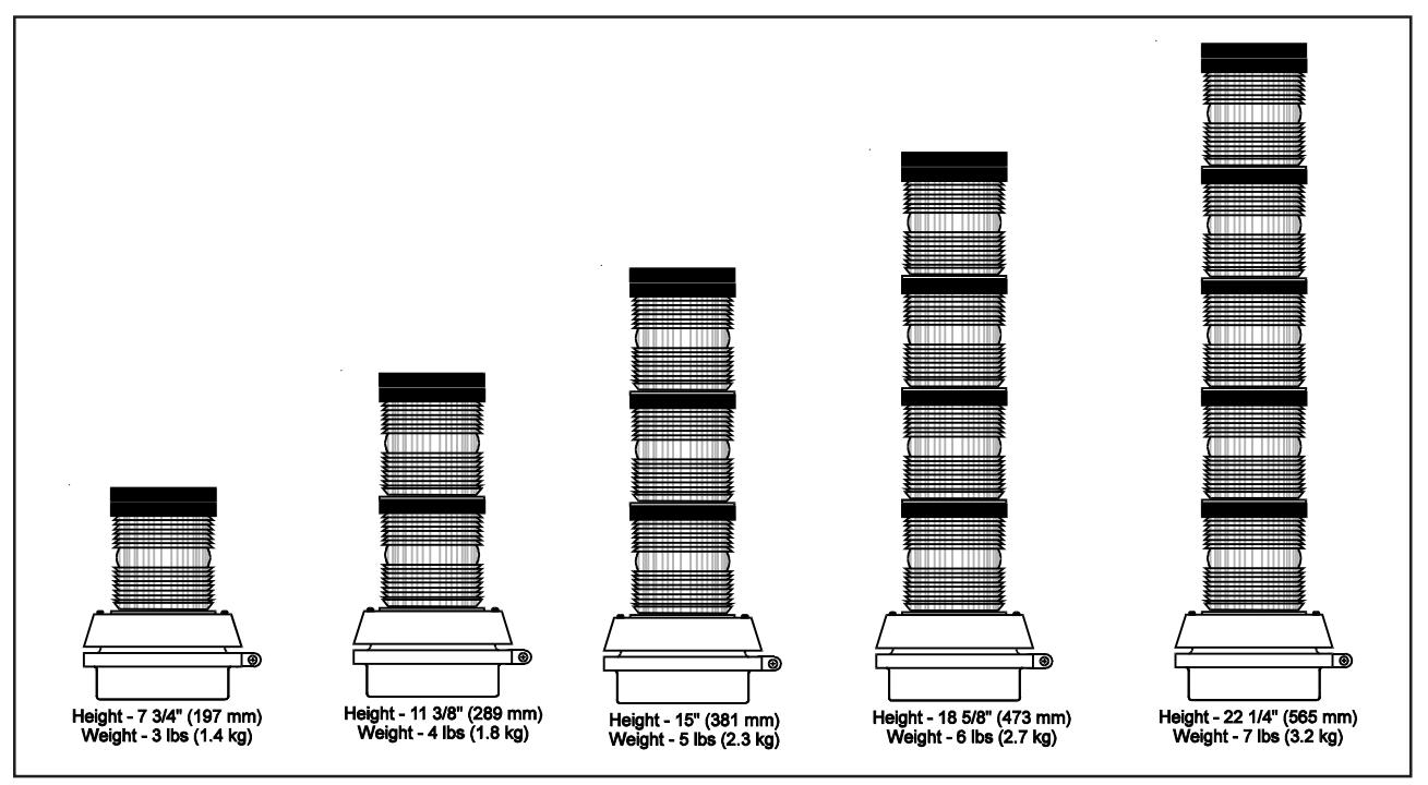
Figure 1. Dimensions
Description
Edwards AdaptaLight Series 101 Stackable Beacon is a unique signaling appliance which can contain up to five modules, stacked onto a single AdaptaLight Base Unit (as illustrated above). AdaptaLight Modules are available in Steady-On Incandescent (101SIN), Steady-On Halogen (101SINH), Steady-On LED (101SLED), Flashing Incandescent (101FIN), Flashing Halogen (101FINH), Flashing LED (101FLED), or Strobe (101ST). Up to five modules can be used in any position in the AdaptaLight Stackable Beacon.
The 9 watt halogen bulb is rated by the manufacturer at 52 lumens. The 12 watt halogen bulb is rated by the manufacturer at 70 lumens.
The AdaptaLight base unit (101BS) contains a mini pulsating horn rated 85 dB at 10 feet (3.05 m). This horn can operate as a sixth independent signal or with any one of the stacked modules. The base unit has a screw-type terminal strip for positive hard wiring. Each module in the stack is electrically interconnected through solid copper busses and mating contacts to withstand vibration. Each is positively connected to the one below it by a solid through-bolt for mechanical integrity.
AdaptaLight is UL and cUL listed for direct surface or pipe mounting in non-hazardous dust and weatherproof applications. The AdaptaLight may be mounted vertically with lenses facing up or with lenses facing down (on ceiling). The AdaptaLight is not suitable for weatherproof installations when mounted with the lenses facing down. The AdaptaLight must never be mounted horizontally. Assemble and install in accordance with these instructions.
The AdaptaLight modules have double fresnel polycarbonate lenses available in a variety of colors, each providing a 360° non-shadowed light pattern.
PLC Compatibility
The electrical input load requirements for PLC compatible signaling devices are listed in Table 1. Signaling devices may be directly connected to output cards that meet these input load requirements.

WARNING
To prevent electrical shock, do not connect power until instructed to do so.
Installation
This equipment must be installed by a qualified electrician in accordance with the latest edition of the National Electrical Code and applicable local codes.
1. Mount the base vertically either facing up or down using one of the following procedures (Figures 2 and 3).
NOTE: For indoor applications, the base may be direct surface mounted, mounted on a 4" (102 mm) octagon box, or mounted on 1/2" (13 mm) NPT conduit. For outdoor (weatherproof) applications, the base must be conduit mounted vertically facing up.
a. Loosen the screw in the clamp ring, remove ring and set
NOTE: A permanently affixed gasket is supplied on the base. Use care when handling the base unit to prevent tearing of the gasket.
Table 1. PLC Compatibility
| Cat. No. | Operating voltage* | Maximum off state leakage current (mA) | Continuous on current (mA) |
Surge (inrush/duration)
(A/ms**) |
|---|---|---|---|---|
| 101BS-G1 | 24V DC | 25 | 50 | 2/1 |
| 101BS-N5 | 120V AC | 25 | 50 | 2/1 |
| 101SINH( )-G1 | 24V DC | 25 | 320 | 0.36/1 |
| 101SINH( )-N5 | 120V AC | 25 | 110 | 0.5/8 |
| 101SLED( )-G1 | 24V DC | 4 | 65 | 0.07/1 |
| 101SLED( )-N5 | 120V AC | 5 | 25 | 0.09/8 |
| 101FINH( )-G1 | 24V DC | 25 | 320 | 1.2/100 |
| 101FINH( )-N5 | 120V AC | 25 | 110 | 1.15/8 |
| 101FLED( )-G1 | 24V DC | 4 | 65 | 0.07/1 |
| 101FLED( )-N5 | 120V AC | 5 | 25 | 0.09/8 |
| 101ST( )-G1 | 24V DC | 1.5 | 300 | 0.33/1 |
| 101ST( )-N5 | 120V AC | 5 | 120 | 2.1/1 |
* All AC volts at 60 Hz
b. Direct Surface Mounting (indoor installation only)
Remove the two knockouts from the bottom of the base.
Fasten the base to the surface using suitable hardware (not supplied).
d" (102 mm) Octagon Box Mounting (indoor installation only)
Remove the two knockouts from the bottom of the base.
Fasten the base to the octagon box (not supplied) by installing the screws (supplied with the box) through the knockout holes in the base.
d. Conduit Mounting (indoor or outdoor installation)
Install a 1/2" (13 mm) NPT conduit (not supplied). Align the conduit entrance hole on the base with the conduit and rotate base until base is tightly secured.
Route incoming field wiring into the base through the conduit entrance hole.
Up to five high-intensity strobe modules, and/or flashing halogen or LED modules, and/or steady-on halogen or LED modules can be used in any position in the stack. The terminal block labels, 1 through 5, correspond to the stacked modules with 1 being the bottom module on the stack.
Connect field wiring to the terminal block as shown in Figure
Ground the AC AdaptaLights to the grounding screw (Figure 3) in accordance with applicable codes. Place the connected wires inside of the base.
Assemble the base unit and place the base gasket on top as shown in Figure 2.
3. To stack the modules, align the notch on the bottom of the first module with the notch on the base and press into position. Secure by tightening the slotted panhead through-bolt located on the top of the module.
NOTE: Never try to remove the through-bolt from the module.
Install the #8-32 x 3/8" (9.5 mm) plastic panhead screw in the side of the module lens (Figure 5).
Place gasket supplied with module onto the top of the module.
Continue adding modules in this manner as required.
Place the cap supplied with the base unit onto the top module ensuring the gasket is in place. Secure with an o-ring and 3/8" (9.5 mm) cap screw (supplied).
4. Turn on power and verify that module(s) and horn are operating properly.
Maintenance
Refer to "Specifications" for replacement parts.

WARNING
To prevent electrical shock, disconnect all power and wait 5 minutes for stored energy in strobe modules to dissipate before starting work on unit.
- 1. Remove the 3/8" (9.5 mm) cap screw, o-ring and cap from top of unit.
- 2. Remove the #8-32 x 3/8" (9.5 mm) plastic panhead screw from the side of the module lens.
** Amps/milliseconds
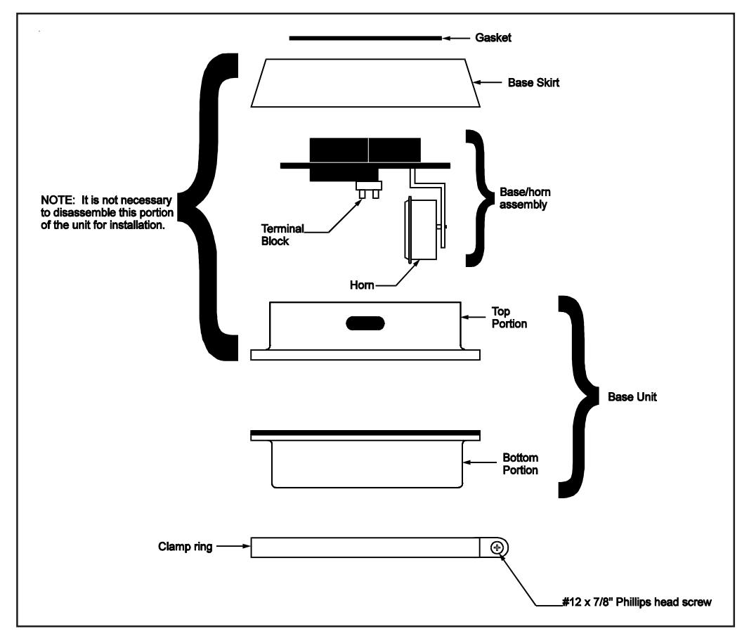
Figure 2. Catalog Series 101BS AdaptaLight Base Unit Assembly
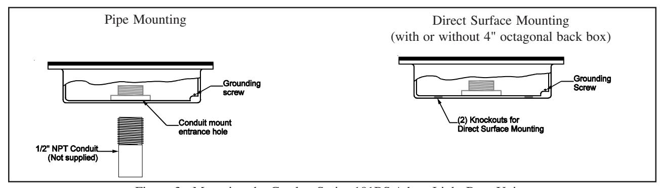
Figure 3. Mounting the Catalog Series 101BS AdaptaLight Base Unit
- 3. Loosen the slotted panhead through-bolt (on top module). Do not remove the through-bolt from the module; turn the bolt approximately 30 turns.
- 4. Carefully remove the module and gasket.
- 5. Continue to disassemble until the component to be replaced is located and replace as follows.

CAUTION
To prevent damage to the lamp, do not touch glass with bare fingers. Grasp glass with a soft, clean cloth or with packaging supplied with the replacement lamp.
-
6. Replace the incandescent or halogen lamp.
- a. Reach inside module, carefully grasp the lamp and press down while turning counterclockwise to release.
- Place new lamp in socket and press down while turning clockwise.
- 7. Replace the strobe tube.

CAUTION
To prevent damage to the strobe tube, do not touch glass with bare fingers. Grasp the base of the replacement strobe tube.
- a. Reach inside module, grasp the base of the strobe tube and remove.
- b. Holding the new strobe tube only by its base (if possible), insert tube in socket.
-
8. Replace mini pulsating horn.
- Remove the screw in the clamp ring, remove ring and set aside.
- b. Remove three phillips head screws from top of base skirt and remove the base skirt and the base/horn assembly from the top portion of the base (Figure 2).
- c. Remove the phillips head screw securing the horn to the mounting bracket (Figure 2).
- d. On DC models, disconnect wire leads from the terminal blocks. On AC models, disconnect wires by cutting off the wire crimp connectors.
- e. Secure the new horn on the mounting bracket with the screw removed in step 8.c.
| Steady-On Incandescent Light Unit* | |||||||||
|---|---|---|---|---|---|---|---|---|---|
| 120V AC | 12V DC | 24V DC | Lens Color | ||||||
| 101SINHR-N5 | 101SINR-E1 | 101SINHR-G1 | Red | ||||||
| 101SINHA-N5 | 101SINA-E1 | 101SINHA-G1 | Amber | ||||||
| 101SINHB-N5 | 101SINB-E1 | 101SINHB-G1 | Blue | ||||||
| 101SINHG-N5 | 101SING-E1 | 101SINHG-G1 | Green | ||||||
| 101SINHM-N5 | 101SINM-E1 | 101SINHM-G1 | Magenta | ||||||
| 101SINHC-N5 | 101SINC-E1 | 101SINHC-G1 | Clear | ||||||
| Steady-On LED Light Unit | |||||||||
| 120 | / AC | 24V DC Lens Color | |||||||
| 101SLE | EDR-N5 | 101SLEDR-G1 | Red | ||||||
| 101SLE | EDA-N5 | 101SLEDA-G1 | Amber | ||||||
| 101SLE | EDB-N5 | 101SLEDB-G1 | Blue | ||||||
| 101SLE | DG-N5 | 101SLEDG-G1 | Green | ||||||
| Flashing Incandescent Light Unit* | |||||||||
| 120V AC | 12V DC | 24V DC | Lens Color | ||||||
| 101FINHR-N5 | 101FINR-E1 | 101FINHR-G1 | Red | ||||||
| 101FINHA-N5 | 101FINA-E1 | 101FINHA-G1 | Amber | ||||||
| 101FINHB-N5 | 101FINB-E1 | 101FINHB-G1 | Blue | ||||||
| 101FINHG-N5 | 101FING-E1 | 101FINHG-G1 | Green | ||||||
| 101FINHM-N5 | 101FINM-E1 | 101FINHM-G1 | Magenta | ||||||
| 101FINHC-N5 | 101FINC-E1 | 101FINHC-G1 | Clear | ||||||
| Flashing LE | D Light Unit | ||||||||
| 120 | / AC | 24V DC | Lens Color | ||||||
| 101FLE | DR-N5 | 101FLEDR-G1 | Red | ||||||
| 101FLE | EDA-N5 | 101FLEDA-G1 | Amber | ||||||
| 101FLE | EDB-N5 | 101FLEDB-G1 | Blue | ||||||
| 101FLE | DG-N5 | 101FLEDG-G1 | Green | ||||||
| Flashing Stro | be Light Unit | ||||||||
| 120V AC | 12V DC | 24V DC | Lens Color | ||||||
| 101STR-N5 | 101STR-E1 | 101STR-G1 | Red | ||||||
| 101STA-N5 | 101STA-E1 | 101STA-G1 | Amber | ||||||
| 101STB-N5 | 101STB-E1 | 101STB-G1 | Blue | ||||||
| 101STG-N5 | 101STG-E1 | 101STG-G1 | Green | ||||||
| 101STM-N5 | 101STM-E1 | 101STM-G1 | Magenta | ||||||
| 101STC-N5 | 01STC-N5 101STC-E1 101STC-G1 Clea | Clear | |||||||
* H in catalog number (e.g., 101SINHR-N5) signifies halogen module.
Stackable Light Units Available
f. On DC models, connect the wires from the horn to the terminal block. On AC models, connect wires using wire nuts (not supplied).
Cleaning
The AdaptaLight module lens surfaces should be periodically dusted and cleaned with a dry soft clean cloth to maintain optimum light visibility. If necessary, the outer lenses may be cleaned with water and a mild detergent on a well rung out soft clean cloth.
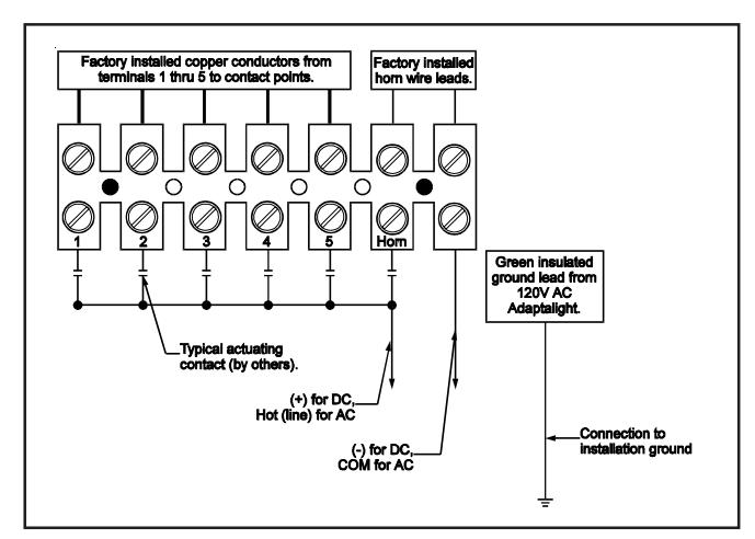
Figure 4. Wiring to the Terminal Block
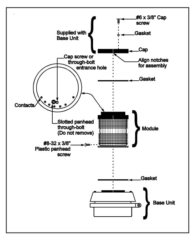
Figure 5. Stacking the Modules on AdaptaLight Base Unit
Table 2. Specifications
| Catalog Number | Voltage | Current | Sound Output |
Lamp
Life |
Light
Output |
Replacement
Horn |
Replacement
Lamp** |
|---|---|---|---|---|---|---|---|
|
101BS-N5
101BS-E1 101BS-G1 |
120V 50/60 Hz
12V DC 24V DC |
0.05A | 85 dB at 10 ft. (3.05 m) | _ |
123A-N5
122-E1 122-G1 |
||
|
101SINH*-N5
101SIN*-E1 101SINH*-G1 |
120V 50/60 Hz
12V DC 24V DC |
0.11A
1.0A 0.32A |
25,000 hr.†
1,520 hr.† 15,000 hr.† |
70 lumens#
189 lumens# 52 lumens# |
50LMP-12WH-D***
Ind. Trade 94 50LMP-9WH-D*** |
||
|
101SLED*-N5
101SLED*-G1 |
120V 50/60 Hz
24V DC |
0.022A
0.062A |
100,000 hr.† | ||||
|
101FINH*-N5
101FIN*-E1 101FINH*-G1 |
120V 50/60 Hz
12V DC 24V DC |
0.11A
0.10A 0.32A |
25,000 hr.†
1,520 hr.† 15,000 hr.† |
70 lumens#
189 lumens# 52 lumens# |
50LMP-12WH-D***
Ind. Trade 94 50LMP-9WH-D*** |
||
|
101FLED*-N5
101FLED*-G1 |
120V 50/60 Hz
24V DC |
0.022A
0.062A |
100,000 hr.† | ||||
|
101ST*-N5
101ST*-E1 101ST*-G1 |
120V 50/60 Hz
12V DC 24V DC |
0.12A
0.5A 0.3A |
3,000 hr.‡ |
300,000
peak candela |
91B-ST |
* Letter in this position specifies lens and LED color: A - amber, B - blue, C - clear, G - green, M - magenta, R - red.
NOTE: LED modules are only available in amber, blue, green and red.
** The LED modules are permanently installed.
*** A non-halogen bulb may be used in place of the halogen bulb as follows. For 120V models, use Lamp Industry Trade No. 15T7DC and for 24V DC models, use Lamp Industry Trade No. 1692.
† Projected lamp life based on manufacturer's calculated lamp life @ 65 fpm and 50% duty cycle.
& lt;sup>‡</sup>Calculated strobe tube life at operating power to 75% efficiency.
# Manufacturer's lumen rating.