E77-Programming Guide
Open the original PDF document
View PDF

[t] 800.413.8783 ■ 805.494.0622 ■ E-mail: service@sdcsecurity.com ■ 801 Avenida Acaso, Camarillo, CA 93012 ■ PO Box 3670, Camarillo, CA 93011
PROGRAMMING GUIDE
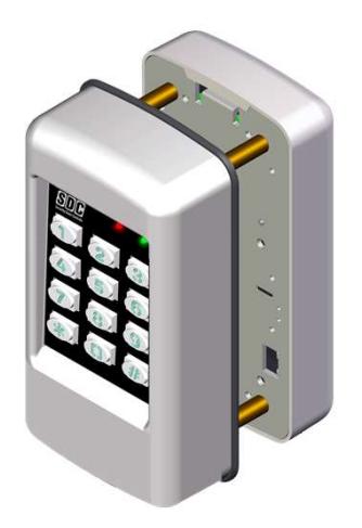
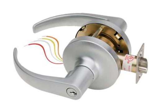
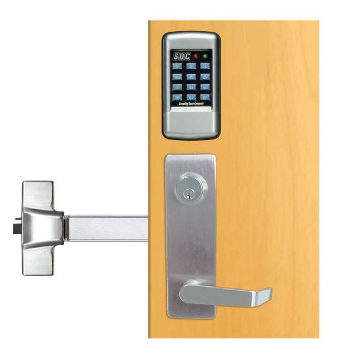
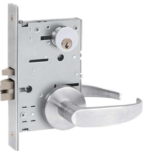
E75 / E76 / E77 STAND ALONE ELECTRONIC LOCKSET
(1) Pre - Initialization
To test lock operation before initialization,
- 1) Apply Power (Plug in the battery pack)
2) Enter *741. This temporary code will unlock the lockset keypad for testing purposes. Once a lock initialization has been performed, this code is no longer active until a hardware reset is performed which will erase all the users and return the lockset keypad back into the uninitialized factory default condition.
(2) Lock Initialization
When the lock is first installed or after a hard reset has been performed, the lockset keypad must be initialized and a lock ID must be entered before you will be allowed to enter programming mode. To initialize the lock :
Press #9*123456#4-digit Lock ID#
The example below assigns a Lock ID of 0001. If Multiple locks are to be used with the E7 Management Software, each lock must have it's own Unique 4-digit Lock ID (0002, 0003 etc)
EXAMPLE: Press #9* 123456# 0001#
Entering and Exiting Programming Mode
IMPORTANT: You must enter Programming Mode before performing any other programming function.
Enter Programming Mode: #9# User No# User PIN#
1) Press #9# 01# 123456# then flashing amber while in programming mode. User 01 is the administrator and has full programming rights. The default Administrator Pin code is 123456. It is recommended that the Admin Pin code be changed using the function 03 below. 20 seconds of inactivity will automatically return you from programming mode to operational mode.
Exit Programming Mode: **#
Press **#
(NOTE: The lockset keypad will automatically exit programming mode after 20 seconds of inactivity.)
Changing the Master PIN Code: 03# 01# PIN Code # Pin Code #
Example: Press 03# 01# 987654# 987654# You have just Changed the Administrator Pin code to 987654 The Administrator's PIN code must be 6 digits in length.
PROGRAMMING FUNCTIONS INDEX
| CODE | FUNCTION | PAGE |
|---|---|---|
| 01 | ADD SINGLE PIN CODE USER | 3 |
| 02 | DELETE SINGLE USER (ALL MODELS) | 3 |
| 03 | CHANGE A USER'S PIN CODE | 3 |
| 03 | ADD/CHANGE PIN TO A PROX CARD USER | 5 |
| 04 | CHANGE USER'S GROUP (ALL MODELS) | 3 |
| 05 | SET ENTRY MODE (PROX ONLY) | 5 |
| 06 | ADD/REPLACE A PROX CARD (PROX ONLY) | 5 |
| 07 | BATCH ENROLL CARDS (NON-SEQUENTIAL) | 5 |
| 08 | BATCH ENROLL CARDS (SEQUENTIAL) | 5 |
| - | - | - |
| 21 | SET OPEN/UNLOCK TIME | 8 |
| 22 | ENABLE MANUAL OVERRIDE MODE | 6 |
| 23 | DISABLE MANUAL OVERRIDE MODE | 6 |
| 24 | ENABLE GROUP | 4 |
| 25 | DISABLE GROUP | 4 |
| 26 | ENABLE USER | 3 |
| 27 | DISABLE USER | 3 |
| 28 | AUTO DELETE TEMP USERS WHEN EXPIRED | 3 |
| 29 | USER LOCKOUT MODE | 6 |
| 30 | SET DATE | 7 |
| 31 | SET TIME | 7 |
| 32 | SET PASSAGE SCHEDULE | 6 |
| 33 | ASSIGN GROUP SCHEDULE | 4 |
| 34 | SET ACCESS SCHEDULE | 4 |
| CODE | FUNCTION | PAGE |
| 35 | SET TEMPORARY USER ACCESS PERIOD | 3 |
| 36 | SET DAYLIGHT SAVINGS TIME | 7 |
| 37 | ENABLE DAYLIGHT SAVINGS TIME | 7 |
| 38 | FIRST SUPERVISOR TO ARRIVE | 6 |
| 39 | SET HOLIDAYS | 7 |
| 40 | TWO USER CODES REQUIRED | 4 |
| 41 | REMOTE INPUT ENABLE | 8 |
| 42 | REMOTE INPUT CONFIGURATION | 8 |
| 43 | DOOR POSITION SWITCH ENABLE | 9 |
| 44 | DOOR STATUS SWITCH CONFIGURATION | 9 |
| 45 | ENABLE FORCED DOOR ALARM | 7 |
| 46 | ENABLE DOOR PROP ALARM | 7 |
| 47 | SET DOOR PROP ALARM TIMER (SECONDS) | 8 |
| 48 | ENABLE BEEP ON FORCED DOOR/DOOR PROP | 7 |
| 50 | ENABLE DURESS ALARM | 9 |
| 51 | ENABLE AUX RELAY ON KEYPAD LOCKOUT | 9 |
| 52 | ENABLE AUX RELAY ON ACCESS GRANTED | 9 |
| 53 | ENABLE AUX RELAY ON FIRST KEY PRESS | 9 |
| 60 | NO. OF INVALID ENTRIES BEFORE KP LOCKOUT | 8 |
| 61 | SET KEYPAD LOCKOUT TIMER (SECONDS) | 8 |
| 62 | BEEP ON KEYPRESS | 9 |
| 63 | SET ANTI-PASSBACK TIME | 8 |
| 80 | ENABLE BLUETOOTH COMMUNICATIONS | 8 |
| 99 | CLEAR ALL USER PROGRAMMING | 10 |
Quick Start Programming Scenario
All users are assigned to Group 06 (24/7 Access and enabled by default). Unlock Time = 3 seconds.
- 1. Enter Programming Mode, Page 1
- 2. Set Date Function 30, Page 7
- 3. Set Time Function 31, Page 7
For Keypad ONLY users
4a. Add Users – Function 01, Page 3 (Group No. = 06)
For Proximity Card Reader users
- 4b. Add Card User(s) Function 06 or 07 or 08, Page 5
- 5. Exit Programming Mode, Page 1
After programming is complete, it is highly recommended that the Administrator PIN Code be changed, and stored in a secure location by the end-user. (Function 03, Page 1)
User Programming
Each user must be assigned a 4 to 6 digit PIN code and assigned to one of the 32 available user groups. Group 06 by default has 24/7 access rights but no programming rights. User 01 is the administrator and has all programming and access rights. User 01 is the only administrator and is always assigned to Group 1. If users are to be assigned scheduled access (i.e. non 24/7 access), proceed to Group access scheduling on the next page, and then add users.
Add a User: 01# User No.# PIN Code # Pin Code # Group No.#
Example: Press 01# • • 04# • • 5555# • • 5555# • • 06# • • • 06# • • • • • • • • • • • • • • • • • • •
You have just added User #04 with a PIN of 5555. User 4 has also be assigned to group 06 (24/7 access).
See the next page for an explanation of
Group programming levels.
PIN Code = 4 to 6 digits Group No. = 2 digits (02-32)
User No = 2 to 4 digits (02-3000)
Delete a User: 02# User No.#
Example: Press 02# 1 04# 1 04# 1 04
You have just Deleted User #04. NOTE: User 01 cannot be deleted.
Change a User PIN Code: 03# User No.# New PIN Code # New Pin Code #
Example: Press 03# • • • 05# • • 1220# • 1220# • 1220# • • • • • • • • • • • • • • • • • • •
You have just Changed User #05's Pin code to 1220
The Administrator's PIN code must be 6 digits in length. All other PIN codes may be 4-6 digits in length
Change a User Group: 04# User No.# New user Group
Example: Press 04# 1 05# 1 02# 1 002# 1 000
You have just Changed User #05's group to Group 02.
Enable a User (after disabling using Function 27): 26# User No.#
Example: Press 26# 1 04# 1 04# 1 You have just re-enabled User #04.
Disable a User: 27# User No.#
Example: Press 27# 1 04# 1 04# 1
You have just disabled User #04. Use Function 26 to re-enable. NOTE: User 01 cannot be disabled.
Any user (except the Administrator) can be made a temporary user by assigning a temporary period start date and an end date. Once the temporary period has expired, the user is either deleted from the system or is set to disabled status. Disabled users can be enabled again by using function 26.
Assign User as Temporary: 35# User Number# Start Date# End Date#
Example: Press 35# 4 008# 4 000000000000000000000000000000000000
User 08 is set as a temporary user and will become active on 03/01/2013. On 12/31/2013 user 08 will either be
disabled or deleted from the system.
User = 02-3000 MM = 2 digit Month
Start Date = MMDDYY DD = 2 digit Day End Date = MMDDYY YY = 2 digit Year
Delete Temporary Users when Expired: 28# Status #
Example 1: Press 28# ( 0 0 0 0 0 0 0 0 0 0 0 0 0 0 0 0 0 0 Status = 0 Disable (default)
Temporary users will be disabled but not deleted. 1 Delete
NOTE: Disabled users may be re-enabled using Function 26 above.
Example 2: Press 28# 1 1# 1 1
Temporary users will be deleted when expired.
Group Programming
By default, group 06 is set for Access 24/7 and is automatically enabled. Groups 02 through 32 must have an access schedule or schedules (up to 3) assigned to them. A group that does not have at least one access schedule assigned to it will not be enabled.
4 levels of programming rights and authority are pre-assigned to user groups as follows:
Group 01 = Administrator: Full Programming Rights ( User 1 is the only user in this group. )
Group 02 = Managers: May perform programming functions 1-39.
Groups 03-05 = Supervisors: May perform programming functions 01, 02, 04, 06, 07,& 08.
Groups 06-32 = Normal User: No programming rights. Access granted upon proper PIN and group access.
To Create an access group:
- 1) Set the Date & Time [Functions 30 & 31, respectively]
- 2) Create or edit an existing Access Schedule(s) [Function34]
- 3) Assign an Access Schedule(s) to the group [Function 33]
Create or Change Access Schedule: 34# Schedule No.# Days # Period Start Time# Period End Time#
Example: Press 34# 02# 8# 0700# 1600#
Access Schedule 02 will enable access Monday thru Friday between 7am and 4pm.
Schedule No. = 01-32 Days = Day(s) of the week:
Period Start Time = HHMM (24hr format) 0 = no access
Period End Time = HHMM (24hr format) 1 thru 7 = Days of the week [Mon=1 Tues=2 ..Sun=7]
8 = Monday thru Friday 9 = Saturday & Sunday
10 = All Days
11 = Override Holidays
Assign Group Access Schedule: 33# Group No# Schedule No 1# Schedule No 2# Schedule No 3#
Up to 3 schedules may be assigned to a Group
Schedule No. = 01-32 Example: Press 33# 04# 08# # #
As created using Function 34 above. Access schedule 08 has been assigned to user group 04
Enable a Group (after disabling using Function 25): 24# Group No.#
Example: Press 24# 02# Group No. = 02-32
You have just enabled user group #02 .
Disable a Group: 25# Group No.#
Group No. = 02-32
Example: Press 25# 02# You have just disabled user group #02.
2 User Codes Required for Entry: 40# Status #
Example 1: Press 40# 0#
Status = 0 One user (default) = 1 Any two users One user code required for entry.
= 2 Two users (one must have Supervisor rights or better) Example 2: Press 40# 1#
Two user codes required for entry.
Access Card Programming (Prox Units Only)
New card users will automatically be assigned to Group 6 and no PIN. Group 06 (by default) has 24/7 access rights but no programming rights. PIN codes may be added to Card only users using Function 03 below. You may also add a card to an already existing PIN Only user. The card will have the same access rights as the existing PIN code. User 01 cannot be assigned a card. User access rights may be changed individually using Function 04 below, or on a Group basis using Function 34 on the previous page.
Add or Change a User Card: 06# User No.# Present Card #
Example: Press 06# 04# Present Card # You have just added a card as User #4. User 4 has been assigned to group 06 (24/7 access).
Delete a Card: 02# User No.#
Example: Press 02# 04# You have just Deleted User #04
Batch Enroll Cards (Non Sequential Cards): 07 # 1st User No.# Total Number of cards to Add# Present 1st Card , 2nd Card ,….. Last card#
Example: Press 07# 05# 03# Present 1st Card 2nd Card 3rd Card You have just enrolled the 3 presented cards. They are users 05,06 & 07. All of the cards were assigned to group 06 (24/7 access).
Batch Enroll (Sequential Cards): 08# Starting User No.# No. of Cards #Present 1st Card
Example: Press 08# 05# 06# Present 1st Card You have just enrolled a 6 sequentially numbered cards. They are users 05 thru 10. All of the cards were assigned to group 06 (24/7 access).
No. of Cards = 01-50 Maximum is 50 cards at a time.
Add/Change a User PIN Code: 03# User No.# New PIN Code # New Pin Code #
Example: Press 03# 05# 1220# 1220# You have just Changed User #05's Pin code to 1220 PIN codes may be 4-6 digits in length
Change a User Group: 04# User No.# New user Group
Example: Press 04# 05# 02# You have just Changed User #05's group to Group 02.
Set Entry Mode: 05# Status #
Example 1: Press 05# 1# Access is by PIN or Card.
Example 2: Press 05# 3# Access is by PIN + Card
Status = 1 PIN or Card (default) 2 Card Only
3 PIN + Card
Manual Passage Programming
The lockset keypad can be programmed to automatically unlock for a preset period of time allowing free egress and ingress without using a PIN . This is called the passage mode. Once a schedule has been programmed , the lockset keypad will continue to follow the schedule indefinitely until the schedule is cleared. The schedule can be temporarily overridden using function 22 or 23.
Set Passage Schedule: 32# Days # Unlock Time# Lock Time#
Example: Press 32# 8# 0700# 1600#
The lockset keypad will automatically unlock Monday thru Friday between 7am and 4pm.
Example: Press 32# 0#
The Passage Schedule has been cleared.
Unlock Time = HHMM (24hr format) Lock Time = HHMM (24hr format)
Days = Day(s) of the week:
0 = Clear passage schedule
1 thru 7 = Days of the week [Mon=1 Tues=2 ..Sun=7]
8 = Monday thru Friday
9 = Saturday & Sunday
10 = All Days
Manual Unlock (Override): 22# Unlock Period (Hours)#
Example: Press 22# 02#
The door will remain unlocked for 2 hours, overriding the passage schedule (Function 32).
Unlock Period = HH (24hr format)
Manual Lock (Override): 23#
Example: Press 23#
The lockset keypad will immediately lock overriding the passage schedule. Normal passage schedule will resume the next day.
First Supervisor to Arrive: 38# Status #
Example 1: Press 38# 0# All schedules operate normally.
Status = 0 Disable (default) 1 Enabled
Example 2: Press 38# 1#
Normal users (Group 6-32) and passage schedules will be delayed until a supervisor/manager (Groups 1-5) has accessed the lockset keypad.
User Lockout: 29# Status #
When enabled, access for users in groups 03-32 are blocked. Only users in Group 1 & 2 have programming rights to access this function.
Example 1: Press 29# 0#
Status = 0 Disable (default)
1 Enabled
Example 2: Press 29# 1# Access for users in groups 03-32 are blocked.
Clear all Programming : 99# 000000 #
Access is normal per group schedules.
Example 1: Press 99# 000000 #
All user codes and programming is erased and all functions are set to factory defaults.
Time And Date Settings
Set the Date: 30# MMDDYY#
Example: Press 30# (100 011513 # (100 010) MM = 2 digit Month The date is set for January 15 th 2013 DD = 2 digit Day YY = 2 digit Year
Set the Time: 31# HH MM#
Example: Press 31# 👊 1320 # 👊 HH = Hours (24hr format) The time is now set to 1:20 PM. MM = Minutes (24hr format)
Set Daylight Savings Time (DST): 36# Start Date# End Date#
Example: Press 36# 0310# 1103# 1103# 100 100 100 100 100 100 100 100 100 10 Daylight Savings Time has been set to start on March 10<sup>th</sup> and end on November 3<sup>rd</sup> of the current year.
Start Date = MMDD MM = 2 digit Month End Date = MMDD DD = 2 digit Day
Enable Daylight Savings Time: 37# Status #
Example 1: Press 37# ( 0 0 0 0 0 0 0 0 0 0 0 0 0 0 0 0 0 0
Status = 0 Disable (default) Daylight Savings Time will not start/end on the programmed dates 1 Fnabled
Example 2: Press 37# (1) 1# (1) (1)
Daylight Savings Time will start/end at 2am on the programmed dates.
Set Holidays: 39# Holiday No. # MMDD#
Groups 02-32 will be blocked from having access on these days unless holiday is overridden within the group schedule.
Example 1: Press 39# • 06# 1225# 1225# • • • • • • • • • • • • • • • • • • • Holiday 06 is set for Dec 25th.
Holiday No = 1-32, 33= Clear All Holidays MMDD = Date MM = 2 digit Month DD = 2 digit Day Example 2: Press 39# ( ) 33# ( ) ( )
All holidays are cleared.
Alarm Settings
Enable Forced Door Alarm: 45# Status # Status = 0 Disabled (default) 1 Enabled
Example 1: Press 45# 1# 1# 1
Forced Door Alarm is enabled. Also requires Function 43 be enabled. On activation, the auxiliary relay will activate until a valid user code or card is presented.
Enable Door Prop Alarm: 46# Status #
Status = 0 Disabled (default)
1 Enabled Example 1: Press 46# 1 1# 1 1# 1
Door Prop Alarm is enabled. Also requires Function 43 be enabled. On activation, the auxiliary relay will activate until the door closes.
Enable Local Alarm on Forced Door/Door Prop: 48# Status #
Status = 0 Disabled (default) Example 1: Press 48# • • 1# • • 1 1 Enabled
The lockset keypad will beep upon a forced door or door prop condition until the condition is cleared.
Timer Settings
Set Unlock Timer: 21# Seconds#
Seconds = 01-100Example: Press 21# 0 03 # 0 0 0 0 0 0 0 0 0 0 0 0 0 0 0 0
Unlock timer is set for 03 seconds. (default)
Set Door Prop Timer: 47# Seconds#
Example: Press 47# • 20 # • • • • • • • • • • • • • • • • • • Seconds = 10-255
Door Prop timer is set for 20 seconds. (default)
Set Anti-Pass back Timer: 63# Seconds#
Example: Press 63# 4 20 # 4 Seconds = 0-100 (0 sec= off [default])
Anti-Pascack timer is set for 20 seconds. User must wait 20 seconds before using the same PIN or card will grant access.
Set Keypad Lockout Timer: 61# Seconds#
Example: Press 10 # Seconds = 10-255 (10 sec = default)
Keypad Lockout timer is set for 10 seconds. Access will be denied for 10 seconds after the number of unsuccessful code attempts (as defined by Function 60) have been made.
Keypad Lockout Attempts: 60# Attempts#
Example: Press 60# • 06 # • • • • • • • • • • • • • • • • • • Attempts = 1-9 (3 attempts = default)
After 6 unsuccessful code attempts, The lockset keypad will shut down and access will be denied for the duration of the
keypad lockout timer (function 61)
Remote Input Configuration
Remote Input Enable: 41# Status #
Status = 0 Disabled (default) Example 1: Press 41# (1) 1# (1) (1) 1 Enabled Remote Input is Enabled.
Remote Input Configuration: 42# Status #
Status = 0 Momentary input unlocks (default). Example 1: Press 42# (1) 2# (1) (1)
1 Momentary input toggles the lock (lock/unlock). A Maintained input puts the lockset keypad in Lockout Mode.
2 Maintained input activates User Lockout Mode
(Same as Function 29)
Bluetooth Communications (Model E75PS Only)
Bluetooth Enabled: 80#
Example: Press 80# • then right LED flashes blue. Bluetooth Communication is enabled. It remains enabled for 2 minutes after the last communication activity.
Bluetooth disabled (while right led flashes blue): Press *
Example: Press * • • • • • • • • • • • • • • • • • •
Lock will return to Programming mode.
Door Status Input Configuration
Door Status Input Enable: 43# Status #
Status = 0 Disabled (default)
1 Enabled
Example 1: Press 43# 1#
The Door Status Input is Enabled. Required for Forced Door & Door Prop alarm monitoring.
Door Status Input Configuration: 44# Status #
Status = 0 Normally Closed (N/C) (default).
1 Normally Open (N/O)
Example 1: Press 44# 1#
The polarity of the door contact is open when the door is closed.
Panic Alarm Configuration
Enable Duress Alarm: 50# Status #
Status = 0 Disabled (default)
1 Enabled
Example 1: Press 50# 1#
Duress Alarm is enabled. Pressing 99 * User PIN # or (99* + card) will unlock the door & momentarily trigger the
auxiliary relay.
Auxiliary Relay Configuration
Enable Aux Relay on Keypad Lockout : 51# Status #
Status = 0 Disabled (default)
1 Enabled
Example 1: Press 51# 1#
The Aux relay will momentarily activate when the lockset keypad has entered the Keypad Lockout Mode.
Enable Aux Relay on Access Granted : 52# Status #
Status = 0 Disabled (default)
1 Enabled
Example 1: Press 52# 1#
The Aux relay will momentarily activate when the lockset keypad has been unlocked by an authorized PIN Code or card.
Status = 0 Disabled (default) Enable Aux Relay on 1st Key Pressed : 53# Status #
1 Enabled
Example 1: Press 53# 1#
The Aux relay will momentarily activate when the lockset keypad is initially pressed after being in standby mode.
Keypad Sound Configuration
Status = 0 Disabled Beep on Keypress : 62# Status #
1 Enabled (default)
Example 1: Press 62# 1#
When entering a PIN code, the lockset keypad will beep each time you a key is pressed. (NOTE: If this function is
disabled, the keypad will still beep while in programming mode.)
Returning the lockset keypad to Factory Defaults
Clear all Programming : 99# 000000 #
Example 1: Press 99# 000000 #
All user codes, groups, schedules, lock parameters, and audit trail information is set to factory defaults. The lock ID & Administrative PIN are not affected.
Hardware Reset to Factory Settings
A hardware reset will erase all the data and return the lockset keypad back into the uninitialized factory default condition.
- 1) Remove power (Unplug the battery pack) and wait approximately 10 seconds.
- 2) Short and hold the 2 Brn reset wires together
- 3) Apply power. (Plug in the battery pack)
The LED will momentarily turn solid RED while data is cleared, and then flash Red/Grn completing the initialization process. When reset is complete, you will here 3 beeps.
- 4) Remove power (Unplug the battery pack)
- 5) Disconnect and insulate the Brn Reset wires.
- 6) Follow the Pre-Initialization & Lock Initialization procedures on Page 1.
Features:
- Number of Users: Up to 3,000 access codes per door. (Up to 32 users may be temporary users)
- Flexible Programming: May be programmed at the lock keypad or by Management Software via the wireless link.
- Passage Mode Options:
First manager in (or privileged user)
Automatically according to access schedules
Manually toggled on / off at lock
Scheduling Options:
User Access Schedules—Up to 32 different access schedules may be programmed into lock
Access Groups – Up to 32 different access groups
Holiday/Vacation—Up to 32 different holiday/vacation blocks may be programmed into lock
Authority Levels: Different levels allow you to control who has access to specific lock functions, includes:
Administrator Level—performs all set-up and programming functions
Manager Level—may perform most programming functions
Supervisor Level—administers common programming functions
Normal Access User Level—entry granted with valid PIN
- Anti-tamper lockout: Adjustable invalid attempts with an adjustable lockout period of up to 255 seconds
- Low Battery Notification