DynaLock 8500 Series Brochure
Open the original PDF document
View PDF

8500 Series
Communicating Bathroom Systems
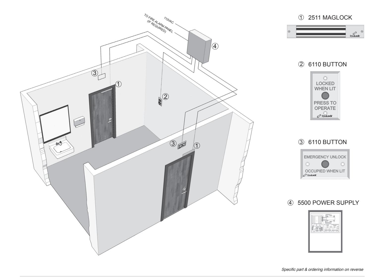
Application
Communicating Bathroom Systems ensure privacy for the occupant of a single bathroom shared by adjacent rooms. The system also allows for emergency access should the need arise. Typical installations include hospitals, nursing and convalescent homes, schools and dormitories.
LIFE SAFETY PRODUCTS FULLY INTEGRATED SECURITY SYSTEMS
Electromagnetic Locks | Controls | Power Supplies
8500 Communicating Bathroom
System Description of Operation
When the bathroom is not occupied all doors are normally closed and unlocked. All switch indicators are not illuminated. Upon entering the bathroom from one of the rooms the occupant presses the inside pushbutton switch to lock all doors. All doors must be closed for locking to occur. Interior and exterior indicators will illuminate red to indicate bathroom is occupied and doors are locked. To unlock doors and exit, occupant presses inside pushbutton again. All indicators will extinguish and all doors will unlock. Depressing outside emergency pushbutton switches, located above or adjacent to each door, will unlock all doors. Outside pushbutton, if used, must be pushed again to reset system to normal use. When connected to a fire panel system all doors will unlock during a fire emergency.
Model 8500-2
Two Door Communicating Bathroom System
System Components
(2) 2511-DSM Maglock with door status switch (1) 6110-CB-ILM-24V Red pushbutton, SPDT, maintained
silk screened "LOCKED WHEN LIT, PRESS TO OPERATE"
(2) 6110-EO-ILM-24V Red pushbutton, SPDT, maintained
silk screened "EMERGENCY UNLOCK, OCCUPIED WHEN LIT"
(1) 5500-FAC-ILB-24V Power supply, 24VDC, 2A (1) 900274 System wiring diagram
When ordering, simply specify "8500-2"
Model 8500-3
Three Door Communicating Bathroom System
System Components
(3) 2511-DSM Maglock with door status switch (1) 6110-CB-ILM-24V Red pushbutton, SPDT, maintained
silk screened "LOCKED WHEN LIT, PRESS TO OPERATE"
(3) 6110-EO-ILM-24V Red pushbutton, SPDT, maintained
silk screened "EMERGENCY UNLOCK, OCCUPIED WHEN LIT"
(1) 5500-FAC-ILB-24V Power supply, 24VDC, 2A (1) 900419 System wiring diagram
When ordering, simply specify "8500-3"
DYNALOCK CORPORATION
705 EMMETT STREET / PO BOX 2728 BRISTOL, CT 06011-2728 PHONE: 877-DYNALOCK / FAX: 860-585-0338 F-MAII: INFO@DYNALOCK.COM
E-MAIL: INFO@DYNALOCK.COM WEBSITE: WWW.DYNALOCK.COM