DynaLock 7400 & 7450 Series Installation Instructions
Open the original PDF document
View PDFInstruction Manual
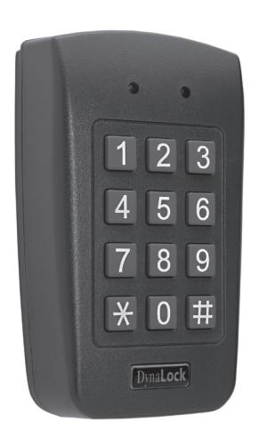
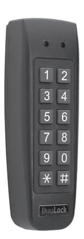
Dyna Lock
(877) DYNALOCK
WWW.DYNALOCK.COM
Table of Contents
| 1. | GENERAL INFORMATION | 4 |
|---|---|---|
| 1.1 | INTRODUCTION | 4 |
| 1.2 | KEYPAD TYPES | 4 |
| 1.3 | BOX CONTENT | 5 |
| 1.4 | ANCILLARY EQUIPMENT | 5 |
| 1.5 | TECHNICAL SPECIFICATIONS | 6 |
| 1.6 | KEY FEATURES | 7 |
| 1.7 | FRONT PANEL DESCRIPTION | 8 |
| 2. | INSTALLATION | 9 |
| 2.1 | MOUNTING THE KEYPAD | 9 |
| 2.2 | WIRING THE KEYPAD | 10 |
| 3. | OPERATION | 14 |
| 3.1 | MODES OF OPERATION | 14 |
| 3.1.1 | Normal Mode (Default) | 14 |
| 3.1.2 | Secure Mode | 14 |
| 3.1.3 | Bypass Mode | 14 |
| 3.2 | USER LEVELS | 15 |
| 3.2.1 | Normal Users | 15 |
| 3.2.2 | Secure Users | 15 |
| 3.2.3 | Master Users | 15 |
| 3.3 | SWITCHING MODES | 15 |
| 3.3.1 | Normal to Secure Mode | 15 |
| 3.3.2 | Secure to Normal Mode | 16 |
| 3.3.3 | Normal to Bypass Mode | 16 |
| 3.4 | SPECIAL FEATURES | 17 |
| 3.4.1 | Auxiliary Input & Output | 17 |
| 3.4.2 | Request to Exit Button (REX) | 17 |
| 3.4.3 | Tamper Feature | 18 |
| 3.4.4 | Lockout Feature (Keypad) | 18 |
| 4. | PROGRAMMING | 19 |
|---|---|---|
| 4.1 | INTRODUCTION | 19 |
| 4.1.1 | Entering Programming Mode | 20 |
| 4.1.2 | Exiting Programming Mode | 20 |
| 4.2 | CHANGING THE OPEN CODE | 21 |
| 4.3 | CHANGING NORMAL/SECURE | 21 |
| 4.4 | CHANGING PROGRAMMING CODE | 22 |
| 4.5 | CHANGING NORMAL/SECURE CODE | 23 |
| 4.6 | CHANGING NORMAL/BYPASS CODE | 24 |
| 4.7 | SETTING FAIL SAFE/SECURE | 26 |
| 4.8 | SETTING AUXILIARY MODES | 27 |
| 4.8.1 | General | 27 |
| 4.8.2 | Auxiliary Mode Setting Guide | 28 |
| 4.9 | SETTING LOCK OUT | 32 |
| 4.10 | BACKLIGHT & LED BEHAVIOR | 33 |
| 4.11 | ENROLLING CODES | 34 |
| 4.11.1 |
Primary
Codes Definition |
34 |
| 4.11.2 |
Secondary
Codes Definition |
34 |
| 4.11.3 | Primary & Secondary Enrolling Methods | 35 |
| 4.11.4 | Standard Method for Enrolling Codes | 35 |
| 4.11.5 | Search Method for Enrolling Codes | 36 |
| 4.12 | DELETING CODES | 38 |
| 4.12.1 | Standard Method for Deleting Codes | 38 |
| 4.12.2 | Search Method for Deleting Codes | 39 |
| 4.13 | RELAY CODE ASSIGNMENT | 40 |
| 4.13.1 | Using Standard Method | 40 |
| 4.13.2 | Using Search Method | 41 |
| 4.14 | PIN LENGTH/FACTORY SETTINGS | 42 |
| 4.15 | REPLACE PROGRAMMING CODE | 43 |
| 4.16 | REPLACE NORMAL/SECURE CODE | 43 |
| LIFE TIME WARRANTY | 44 | |
| TECHNICAL SUPPORT | 44 |
1. General Information
1.1 INTRODUCTION
The 7400 & 7450 series are waterproof, stand-alone keypads. Both units are suitable for indoor and outdoor mounting. Each unit accepts up to 500 users and allows entry via a personal identification number (PIN).
1.2 KEYPAD MODELS
The two digital keypads described in this manual are:
- • 7400-Single Gang Box & Wall Mounting, PIN only
- • 7450-Narrow Mullion & Wall Mounting, PIN only
|
MODEL
NUMBER |
RELAY
CURRENT |
BACK
LIGHT |
KEYPAD
TYPE |
|---|---|---|---|
| 7400 | 2A |
3x4
STANDARD |
|
| 7450 | 2A |
2x6
MULLION |
1.3 BOX CONTENT
Before beginning verify that all of the following are in the box. If anything is missing please contact DynaLock for assistants.
- • One Unit
- • One Drilling Template (Label/Sticker)
- • One Security Spline Key
- • One Security Hex Screw
- • Four Mounting Screws and Wall Plugs
1.4 ANCILLARY EQUIPMENT
The following ancillary equipment may be required to complete your installation:
- • Electromagnetic Lock
- • Power Supply with Battery Backup- 12-24VDC or 16-24VAC
- • Request to Exit (REX) button (optional)- normally open type; switch is closed when pressed
- • Magnetic Contact (optional)- installed for door monitor capabilities
THESE PRODUCTS AND OTHER ACCESSORIES CAN BE FOUND AT THE DYNALOCK WEB SITE:
WWW.DYNALOCK.COM
1.5 TECHNICAL SPECIFICATIONS
| 7400 | 7450 | |||
|---|---|---|---|---|
| INPUT | VDC |
12-24
VDC |
||
| VOLTAGE | VAC |
16-24
VAC |
||
|
MAXIMUM
CURRENT (12 |
INPUT
VDC) |
125mA
125mA |
||
|
STANDBY
CURRENT (12 |
INPUT
VDC) |
75mA | 75mA | |
|
MAXIMUM
CURRENT |
RELAY |
2A
2A |
||
|
REX
INPUT |
NORMALLY
OPEN DRY CONTACT |
|||
|
AUXILIARY
INPUT |
NORMALLY
OPEN DRY CONTACT |
|||
|
LED
INDICATORS |
TWO
TRI-COLORED LED'S (MODE & DOOR) |
|||
|
OPERATING
TEMPERATURES |
-22
F TO 150 F (-30 C TO 65 C) |
|||
|
OPERATING
HUMIDITY |
0
TO 95% (NON-CONDENSING) |
|||
|
OUTDOOR
USAGE |
WEATHER
RESISTANT MEETS IP65 EPOXY POTTED |
|||
| SIZE |
H4.72"xW2.80"
xD1.17" |
H5.33"xW1.74"
xD1.12" |
||
| WEIGHT | 0.54LBS | 0.39LBS | ||
1.6 KEY FEATURES
- • 500 Users
- • Water resistant
- • Programmable Backlight and active LED control
- • Three user levels: Normal, Secure, Master
- • Three modes of operation: Normal, Secure, Bypass
- • Integrated keypad for PIN entry
- • Selectable PIN code length from 4 to 8 digits
- • Auxiliary input and output
- • Ten auxiliary modes including: Door Ajar, Forced Door, Shunt, Monitor
- • Input for request to exit (REX)
- • Code search feature for easy maintenance of User Codes
- • Internal buzzer
- • Vandal proof mounting screw (special tool supplied)
- • Two tri-color LED indicators for status and programming interface
- • Built in case and back tamper protection
- • Lockout feature on invalid code entries
- • Programmable lock release time
- • Mounting template included for easy installation
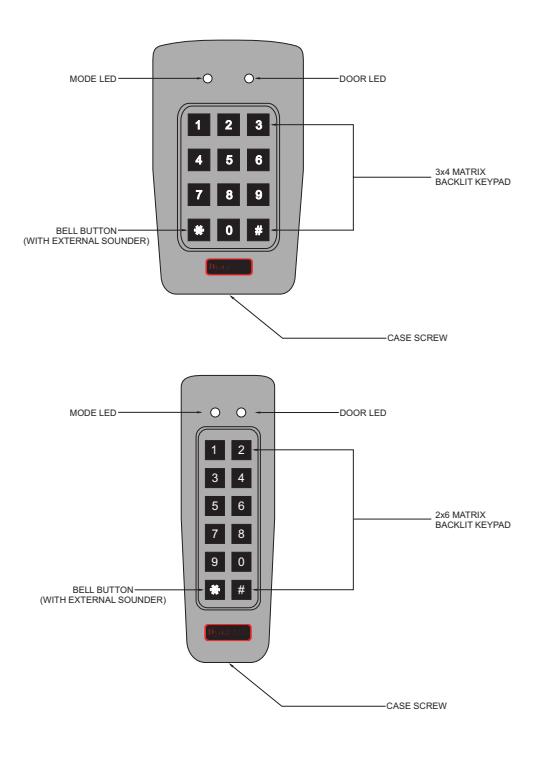
FIGURE 1: FRONT PANEL
2. Installation
2.1 MOUNTING THE KEYPAD
Prior to starting, select the location where the keypad unit is to be mounted.
Perform the following steps:
- 1) Open the keypad by loosening and removing the case security screw located at the bottom using the security spline key.
- 2) Depending on the type of installation, gang box or wall mount, drill the respective holes into the rear cover.
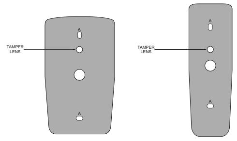
FIGURE 2: DRILLING HOLES IDENTIFICATION
NOTE: THE CENTRAL HOLE IS FOR ROUTING THE WIRING TO THE CONTROLLER
- 3) Use the provided drilling template to accurately locate and drill the required holes in the wall or panel.
- 4) Use the hardware provided to mount the back plate on the wall or gang box. Route the wiring via the large center hole in the back plate. Check to make sure the back plate is level.
- 5) Wire the keypads pre-wired cable as instructed in this manual.
6) Once wired, replace the keypad back onto its back plate and secure using the tamper proof screw and special tool, supplied with the hardware.
2.2 WIRING THE KEYPAD
The keypads are provided with a 3 foot, prewired, 10 conductor 18AWG cable. Wire according to the following steps:
- 1) Cut and strip the conductors to the necessary length.
- 2) Splice the keypad wires to the corresponding ancillary devices and insulate each connection, including any unused wires. Refer to the wiring color guide table and the wiring diagrams, depending on the desired application:
Wiring the Lock Relay & REX (Figure 3) Wiring for Auxiliary Input & Output (Figure 4) Wiring External Sounder (Figure 5)
Wiring for Electromagnetic Locks for Shunt Auxiliary Mode (Figure 6) Wiring an External Sounder for Door Chime (Figure 7)
|
WIRING
COLOR GUIDE |
|||||
|---|---|---|---|---|---|
| COLOR | DESCRIPTION | ||||
| RED |
VOLTAGE
INPUT |
||||
| BLACK | GROUND | ||||
| GREEN | REX/BL | ||||
| WHITE | IN/MONITOR | ||||
| PURPLE |
LOCK:
COM |
||||
| GRAY |
LOCK:
N.O. |
||||
| BROWN |
LOCK:
N.C. |
||||
| BLUE |
AUX:
COM |
||||
| YELLOW |
AUX:
N.O. |
||||
| ORANGE |
AUX:
N.C. |
||||
|
SMALLER
GAUGE BLACK |
RF
SHIELDING WIRE |
||||
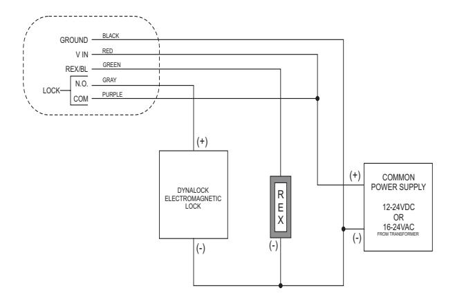
FIGURE 3: WIRING DIAGRAM FOR ELECTROMAGNETIC LOCK RELAY & REX
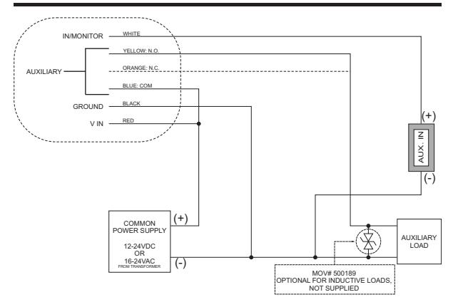
FIGURE 4: WIRING DIAGRAM FOR AUXILIARY INPUT & OUTPUT
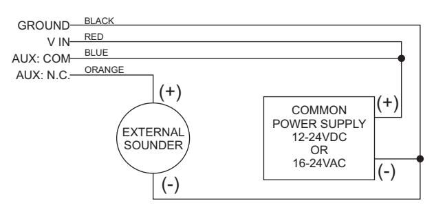
FIGURE 5: WIRING DIAGRAM FOR AN EXTERNAL SOUNDER: AUXILIARY MODE 3
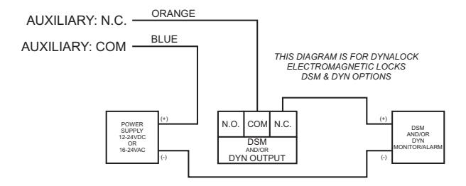
FIGURE 6: WIRING DIAGRAM FOR WIRING DIRECT SHUNT; AUXILIARY MODE 4
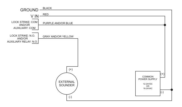
FIGURE 7: WIRING DIAGRAM FOR EXTERNAL SOUNDER FOR "DOOR CHIME" FEATURE
3. Operation
3.1 MODES OF OPERATION
The keypad has three modes of operation. These are indicated by the color of the Mode Indicator LED:
3.1.1 Normal Mode (Default) Mode Indicator is green
In Normal Mode, the door is locked until a valid Primary Code is entered.
THE KEYPAD CAN ONLY BE PROGRAMMED IN NORMAL MODE
3.1.2 Secure Mode Mode Indicator is red
Only Secure or Master users can access the premises in Secure Mode, A Secure user must enter a Primary and Secondary Code to gain entry. Once the Primary Code has been entered, the Door Indicator LED will flash green for 10 seconds. During this time, the Secondary Code must be entered. A Master user only needs to enter their code once to enter.
3.1.3 Bypass Mode Mode Indicator is orange
In Bypass Mode, access to the premises is dependant on the Lock relay; that is, if the relay is programmed for fail-safe or fail-secure operation.
When the Lock relay is programmed for fail-secure operation, the door is locked until the star button (*) is depressed.
When the Lock relay is programmed for fail-safe operation, the door is constantly unlocked.
In case of a power failure, once the power is restored, the keypad will return to Normal Mode, for security reasons.
3.2 USER LEVELS
7400 and 7450 keypads accept up to 500 users and provide entry via the use of PIN Codes. Each user is allocated two memory slots:
1) Primary Code 2) Secondary Code
The way in which the two memory slots are programmed, determines a users access level. It also establishes what access is granted for each of the three modes of operation. There are three user levels:
3.2.1 Normal User
A normal user only has a Primary Code and is granted access only when the keypad is in Normal or Bypass Mode.
3.2.2 Secure User
A secure user must have a Primary and Secondary Code assigned, and the two codes can't be the same. The secure user can gain access in any mode of operation. In Normal Mode the secure user must use the Primary Code to gain entry. In Secure Mode the secure user must first enter the Primary and then the Secondary Code, in order to enter.
3.2.3 Master User
A master user must have an identical Primary and Secondary Code assigned. The codes are entered with the same PIN. The master user can enter during any mode of operation by entering their code once.
3.3 SWITCHING OPERATIONAL MODES
3.3.1 Switching From Normal to Secure Mode
The default factory setting for the Normal/Secure Code is 3838
1) Enter the Normal/Secure code. MODE DOOR GREEN
MODE INDICATOR FLASHES RED MODE DOOR RED
2) Depress the # key to confirm the change.
MODE INDICATOR STAYS RED MODE DOOR RED
3.3.2 Switching From Secure to Normal Mode
The default factory setting for the Normal/Secure Code is 3838 .
1) Enter the Normal/Secure code. MODE DOOR GREEN
MODE INDICATOR FLASHES GREEN MODE DOOR GREEN
2) Depress the # key to confirm the change.
MODE INDICATOR STAYS GREEN MODE DOOR GREEN
The auxiliary mode of the keypad can also be used to switch the mode of operation from Secure to Normal Mode and vice versa. If the auxiliary input is selected it deactivates the Normal/Secure Mode Code. Refer to Setting the Auxiliary Mode , paragraph 4.8.
3.3.3 Switching From Normal to Bypass Mode
By default, there is no Normal/Bypass Mode Code. The Normal/Bypass Code must first be programmed to use this function. Refer to paragraph 4.6 to create or modify the Normal/Bypass Code.
1) Enter the Normal/Bypass code. MODE DOOR GREEN
MODE INDICATOR FLASHES ORANGE MODE DOOR ORANGE
2) Depress the # key to confirm the change.
MODE INDICATOR STAYS ORANGE MODE DOOR ORANGE
3.3.4 Switching From Bypass to Normal Mode
1) Enter the Normal/Bypass code. MODE DOOR ORANGE
GREEN MODE INDICATOR FLASHES GREEN MODE DOOR
2) Depress the # key to confirm
the change.
MODE INDICATOR STAYS GREEN MODE DOOR GREEN
3.4 SPECIAL OPERATIONAL FEATURES
Some installation-specific features are exercised, as required by the system. These features are implemented as shown in Figures 4-6.
3.4.1 Auxiliary Input & Output
For optimum usability in different applications, the keypad's auxiliary input and output can be configured in ten different modes of operation. Refer to Setting the Auxiliary Mode in paragraph 4.8.
3.4.2 Request to Exit (REX)
A REX push button may be located within the premises and used to open the door from the inside. It is usually located in a convenient location (e.g. next to the door at the receptionist's desk). The function of the REX depends on the Lock relay, and wether it is programmed for fail-safe or fail-secure operation.
Fail-Secure Operation: from the moment the REX is depressed, the door will be unlocked until the Lock release time has elapsed. After this time, the door will be locked, even if the REX has not been released. Fail-Safe Operation: from the moment the REX push button is depressed, the door will be unlocked until the REX is released. In this case, the Lock relay only begins its countdown once the REX has been released. This feature is designed to keep the door open, when used in conjunction with fire systems.
3.4.3 Tamper Feature
In case the keypad is forcibly opened or removed from the wall, a tamper event is triggered. A tamper signal is sent to an external sounder (refer to Figure 5 wiring diagram on page 12). The output time can be easily programmed with the keypad from 0 to 9 minutes. The tamper event can activate the auxiliary output if the keypad is in Auxiliary Mode 3. Refer to the Quick Reference Guide for Auxiliary Mode Setting Table in paragraph 4.8.2.
3.4.4 Lockout Feature
In case the keypad is presented with invalid codes several times, consecutively, the keypad will go into lockout mode. When a lockout occurs, the keypad is deactivated so no codes can be entered until the preset lockout period expires. During the lockout, the Mode Indicator LED is off, the Door Indicator LED flashes red, and the keypad beeps every two seconds. Refer to Programming Menu 6 for detailed instructions for this feature.
4. Programming
4.1 INTRODUCTION
Programming is done solely via the keypad driven Programming Menu System. To reach the Programming Menu System, the keypad must first be placed into Programming Mode. Refer to Entering Programming Mode in paragraph 4.1.1.
During the manufacturing process, certain codes and settings are preprogrammed. These settings are the default factory settings.
THE TABLE BELOW SHOWS ALL THE PROGRAMMING MENUS, WITH DEFAULT FACTORY SETTINGS
|
MENU
DESCRIPTION |
DEFAULT | PAGE | ||||
|---|---|---|---|---|---|---|
| No. | 4 DIGIT 5 DIGIT 6 DIGIT 4-8 DIGITS | No. | ||||
| 1 |
CHANGE
OPEN CODE |
2580 | 25802 | 258025 | 25802580 | 21 |
| 2 |
CHANGE
AUXILIARY CODE |
0852 | 08520 | 085208 | 08520852 | 21 |
| 3 |
CHANGE
PROGRAM CODE |
1234 | 12341 | 123412 | 12341234 | 22 |
| 4 |
CHANGE NORMAL/SECURE
CODE |
3838 | 38383 | 383838 | 38383838 | 23 |
| 5 |
CHANGE
NORMAL/BYPASS CODE |
24 | ||||
| 6 |
CHANGE DOOR
RELEASE TIME |
0004 | 26 | |||
| 6 |
DEFINE
AUXILIARY INPUTS/OUTPUTS |
2004 | 27 | |||
| 6 |
SET
LOCKOUT FEATURES |
4000 | 32 | |||
| 6 |
BACKLIGHT
AND LED BEHAVIOR |
5100 | 33 | |||
| 7 |
ENROLL
PIN |
35 | ||||
| 8 |
DELETE
PIN |
38 | ||||
| 9 |
CODE
ASSIGNMENT WITH STRIKE/AUXILIARY |
40 | ||||
| 0 |
RESTORE
DEFAULTS/CHANGE PIN LENGTH |
42 | ||||
TABLE 1 PROGRAMMING MENU
4.1.1 Entering the Programming Mode

Note
- The keypad must be in Normal Mode to enter Programming.
- The factory default 4 digit Programming Code is 1234.
- If a Programming Code is not entered within 5 seconds, the keypad will return to its Normal Mode.
- 1) Depress the # key, in rapid succession.
MODE INDICATOR WILL TURN OFF DOOR INDICATOR WILL TURN RED MODE ○ ● DOOR
2) Enter your Programming Code.
IF THE PROGRAMMING CODE IS VALID, THE DOOR INDICATOR WILL TURN GREEN AND THE KEYPAD WILL ENTER PROGRAMMING MODE.
4.1.2 Exiting the Programming Mode

Note:
- Invalid entries may reset the keypad back to Normal Mode.
- If no keys are pressed for 1 minute, while in Programming Mode, the keypad will exit the Programming Mode and return to Normal Mode.
- 1) To exit the Programming Mode, depress the # key twice, in succession.
YOU WILL HEAR THREE BEEPS THE DOOR INDICATOR TURNS OFF THE MODE INDICATOR TURNS GREEN MODE ● ○ DOOR GREEN
This indicates the keypad has returned to Normal Mode.
4.2 CHANGING THE OPEN CODE
The Open Code is mainly used as a method to quickly test the Lock relay during installation. The factory 4 digit default setting for the Open Code is 2580 . For security reasons when the first user is added to the keypad or the auxiliary code is changed, the default Open Code will automatically be deleted. Non default codes will not be erased automatically.
æ '

- Open Code does not function in Secure Mode.
- Invalid entries; you will hear a long beep and the keypad will return to Normal Mode.
- Code 0000 will erase and deactivate the Open Code.
- 1) Enter the Programming Mode.
- 2) Depress -1- to enter Menu 1.
THE MODE INDICATOR TURNS RED THE DOOR INDICATOR STAYS GREEN
MODE ● DOOR
- 3) Enter the new code you wish to set as the Open Code.
- 4) System returns to Normal Mode.
YOU WILL HEAR 3 BEEPS THE MODE INDICATOR TURNS GREEN MODE ● ○ DOOR THE DOOR INDICATOR TURNS OFF GREEN
4.3 CHANGING THE AUXILIARY CODE
The Auxiliary Code is mainly used as a method to quickly test the auxiliary relay during installation. The default 4 digit factory setting for the Auxiliary Code is 0852 . For security reasons when the first user is added or the Open Code is changed, the default Auxiliary Code will automatically deleted. Non default codes will not be erased automatically.

Note:
- Auxiliary Code does not function in Secure Mode.
- Auxiliary Code only works when the Auxiliary Mode is 0, 1, 8, or 9.
- Invalid entries; you will hear a long beep and the keypad will return to Normal Mode
- Code 0000 will erase and deactivate the Auxiliary Code.
- Enter the Programming Mode.
- 2) Depress -2- to enter Menu 2.
THE MODE INDICATOR TURNS ORANGE MODE • DOOR THE DOOR INDICATOR STAYS GREEN
- 3) Enter the new code you wish to set as the Auxiliary Code.
- 4) System returns to Normal Mode.
YOU WILL HEAR 3 BEEPS THE MODE INDICATOR TURNS GREEN MODE ● ○ DOOR THE DOOR INDICATOR TURNS OFF GREEN
4.4 CHANGING THE PROGRAMMING CODE

Note:
- The code 0000 is not valid, thus the Programming Code cant be erased.
- Invalid entries; you will hear a long beep and the keypad will return to Normal Mode.
- 1) Enter the Programming Mode.
- Depress -3- to enter Menu 3.
THE MODE INDICATOR TURNS GREEN THE DOOR INDICATOR STAYS GREEN MODE ● DOOR GREEN GREEN GREEN GREEN
- 3) Enter the new code you wish to set as the Programming Code.
- 4) System returns to Normal Mode.
YOU WILL HEAR 3 BEEPS THE MODE INDICATOR TURNS GREEN MODE ● ○ DOOR THE DOOR INDICATOR TURNS OFF GREEN
4.5 CHANGING THE NORMAL/SECURE CODE

Note:
- When in Auxiliary Mode 1, 2, 3, or 4 the auxiliary input takes priority over the Normal/Secure Code.
- Invalid entries; you will hear a long beep and the keypad will return to Normal Mode.
- Code 0000 will erase and deactivate the Normal/Secure Code
- 1) Enter the Programming Mode.
- 2) Depress -4- to enter Menu 4.
THE MODE INDICATOR FLASHES RED THE DOOR INDICATOR STAYS GREEN MODE ○ DOOR RED GREEN
- 3) Enter the new code you wish to set as the Normal/Secure Code.
- System returns to Normal Mode.
YOU WILL HEAR 3 BEEPS THE MODE INDICATOR TURNS GREEN MODE ● ○ DOOR THE DOOR INDICATOR TURNS OFF GREEN
4.6 CHANGING THE NORMAL/BYPASS CODE
The Normal/Bypass Code is also used to turn the door chime on and off. Door chime will only function with an external sounder. Refer to Figure 7 on page 13.

Note:
- The chime is only heard when the Lock relay is activated by a valid code entry.
- Invalid entries; you will hear a long beep and the keypad will return to Normal Mode.
- Code 0000 will erase and deactivate the Normal/Bypass Code.
| P | r۸ | aı | ra | m | m | in | • |
|---|---|---|---|---|---|---|---|
| П | U | yı | a | ш | ш | ш | ١ |
- 1) Enter the Programming Mode.
- 2) Depress -5- to enter Menu 5.
THE MODE INDICATOR FLASHES ORANGE THE DOOR INDICATOR STAYS GREEN ORANGE GREEN
- Hereafter, are 4 different ways to program the Normal/Bypass Code and the door chime.
- 3) Hereafter, are 4 different ways to program the Normal/Bypass Code and the door chime.
- A) DISABLE BOTH BYPASS CODE AND DOOR CHIME: ENTER CODE 0000
- B) DISABLE BYPASS CODE AND ENABLE DOOR CHIME: ENTER CODE 0001
- C) ENABLE BYPASS CODE AND DISABLE THE DOOR CHIME: ENTER ANY CODE ENDING WITH 0
- D) ENABLE BOTH BYPASS CODE AND DOOR CHIME: ENTER ANY CODE NOT ENDING IN 0
- 0 0 0 0
- 0 0 0 1
- ? ? ? 0
- ? ? ? 8
- 4) System returns to Normal Mode.
YOU WILL HEAR 3 BEEPS THE MODE INDICATOR TURNS GREEN THE DOOR INDICATOR TURNS OFF
MODE ● ○ DOOR
4.7 SETTING FAIL SAFE/SECURE OPERATION
In this paragraph, the fail-safe/fail-secure operation of the door lock and release time are set. Setting the sounding period for the siren feature requires an external sounder.
- 1) Enter the Programming Mode.
- 2) Depress -6- to enter Menu 6.
THE MODE INDICATOR FLASHES GREEN MODE : THE DOOR INDICATOR STAYS GREEN GREEN GREEN 3) Construct a code using the following instructions. FIRST DIGIT: FOR FAIL SECURE: SET THE 1ST DIGIT TO 0 FOR FAIL SAFF. SET THE 1ST DIGIT TO 1 SECOND DIGIT: SIREN TIME: ENTER 0 TO 9 (MINUTES) THIRD & FOURTH DIGIT. LOCK RELEASE TIME: ENTER 1 TO 99 (SECONDS)
FOR EXAMPLE THE CODE 0512 MEANS:
FAIL SECURE OPERATION (0) WITH 5 MINUTE SIREN TIME (5) 12 SECOND LOCK RELEASE TIME (12)
4) System returns to Normal Mode.
YOU WILL HEAR 3 BEEPS THE MODE INDICATOR TURNS GREEN MODE ● ○ DOOR THE DOOR INDICATOR TURNS OFF GREEN
4.8 SETTING AUXILIARY MODES
4.8.1 General
The default Auxiliary Code is 2004.
Auxiliary Mode
In addition to the Lock relay and the Lock REX, the keypad features an auxiliary output relay and an auxiliary input, whose function is established by the Auxiliary Mode selection (0 thru 9).
The Auxiliary Mode also determines if the auxiliary output relay is set for fail-safe or fail-secure operation. For a detailed explanation of each Auxiliary Mode, refer to section 4.8.2 Quick Reference Guide for Auxiliary Mode Settings.
- 1) Enter the Programming Mode.
- 2) Depress -6- to enter Menu 6.
THE MODE INDICATOR FLASHES GREEN
THE DOOR INDICATOR STAYS GREEN 3) Construct a code using the following instructions, and the Quick Reference Guide for Auxiliary Mode AUXILIARY MODE
AUXII IARY SETTINGS

Auxiliary relay activation is subject to user's Auxiliary Code Assignment (excluding shunt, which is activated by all user's), for a details see paragraph 4.13 Relay Code Assignment.
Auxiliary Settings
Each of the Auxiliary Modes has a 2 digit setting which affects the operation of the related relay(s).
4) System returns to Normal Mode.
YOU WILL HEAR 3 BEEPS THE MODE INDICATOR TURNS GREEN MODE ● ○ DOOR THE DOOR INDICATOR TURNS OFF GREEN
4.8.2 Quick Reference Guide for Auxiliary Mode Setting
|
AUXILIARY
MODE |
AUXILIARY
INPUT FUNCTION |
AUXILIARY
OUTPUT ACTIVATED BY |
AUXILIARY
RELAY |
AUXILIARY SETTINGS
(IN SECONDS) |
| 0 | AUX REX |
VALID CODE OR
AUX REX |
N.O. |
01 TO 99 AUX RELAY RELEASE TIME
00 AUX RELAY TOGGLE |
| 1 |
NORMAL/SECURE
SWITCH |
VALID
CODE |
N.O. |
01 TO 99 AUX RELAY RELEASE TIME
00 AUX RELAY TOGGLE |
| 2 |
NORMAL/SECURE
SWITCH |
STAR BUTTON (*) | N.O. |
01 TO 99 AUX RELAY RELEASE TIME
00 AUX RELAY TOGGLE |
| 3 |
NORMAL/SECURE
SWITCH |
TAMPER
EVENT |
N.C. |
01 TO 99 AUX RELAY RELEASE TIME
00 AUX RELAY TOGGLE |
| 4 |
NORMAL/SECURE
SWITCH |
DIRECT
SHUNT |
N.O. | 01 TO 99 SHUNT TIME |
| 5 | DOOR MONITOR | SHUNT | N.C. | 01 TO 99 MAXIMUM SHUNT TIME |
| 6 | DOOR MONITOR |
FORCED
DOOR |
N.C. | 01 TO 99 FORCED DELAY |
| 7 | DOOR MONITOR |
DOOR
AJAR |
N.C. | 01 TO 99 AJAR DELAY |
| 8 |
LED CONTROL:
GREEN |
VALID
CODE |
N.O. |
01 TO 99 AUX RELAY RELEASE TIME
00 AUX RELAY TOGGLE |
| 9 |
LED CONTROL:
RED |
VALID
CODE |
N.O. |
01 TO 99 AUX RELAY RELEASE TIME
00 AUX RELAY TOGGLE |
4.8.2 Detailed Reference Guide
The following are brief descriptions of each Auxiliary Mode. To implement the features of each mode, refer to Setting the Auxiliary Mode, paragraph 4.8.1.
Auxiliary Mode 0
Auxiliary Input Function: Activates the Aux. Output
Auxiliary Output activated by: Valid User or Aux. Code, Aux. Input Example: the keypad can function as a 2 door controller. The aux. relay is to be wired to the lock on the 2nd door. The Aux. Setting defines the door open time for the 2nd door. The aux. input (white wire) is to be wired to the REX button for the 2nd door. Door Monitor Input is not enabled for the 2nd door in this mode. Refer to Figure's 3 & 4 on pages 11 -12 for wiring the outputs.
Auxiliary Mode 1
Auxiliary Input Function: Toggles Normal/Secure Mode Auxiliary Output activated by: Valid User or Aux. Code
Example : the keypad can function as a 2 door controller. The aux. relay is to be wired to the lock on the 2nd door. REX feature for the 2nd door is not enabled in this mode. The Aux. Setting defines the open time for the 2nd door. The aux. input can switch the mode of operation between Normal & Secure Mode. By wiring a switch timer or an alarm system output to the aux. input, the keypad can automatically switch from Normal Mode (during office hours) to Secure Mode (after office hours).
Auxiliary Mode 2
Auxiliary Input Function: Toggles Normal/Secure Mode
Auxiliary Output activated by: Star Button (*)
Example : aux. relay can function as a time switch, activated by depressing the star (*) button. The Aux. Setting establishes how long the aux. relay is activated. By wiring a switch timer or an alarm system output to the aux. input, the keypad can automatically switch from Normal Mode (during office hours) to Secure Mode (after office hours).
Auxiliary Mode 3
Auxiliary Input Function: Toggles Normal/Secure Mode Auxiliary Output activated by: Alarms
Example : the aux. output is activated if the keypad's case is forcibly opened or removed from the wall. By wiring a switch timer or an alarm system output to the aux. input, the keypad can automatically switch from Normal Mode (during office hours) to Secure Mode (after office hours).
You can't wire a 2nd door in this mode. You can still have door chime feature active for the 1st door. Refer to Figure 5 on page 13 for wiring an external sounder.
Auxiliary Mode 4
Auxiliary Input Function: Toggles Normal/Secure Mode
Auxiliary Output activated by: Direct Shunt (explanation below)
Example : the keypad is capable of bypassing an alarm zone by shunting the door systems sensor. The aux. output is wired to the door sensor output. When in use, the aux. output is normally open and the door sensor functions normally. When a valid code is entered, the aux. relay shunts the door sensor for the duration of the shunt time, as defined by the aux. setting. If the door is left open longer than the shun time, an alarm is triggered. Refer to Figure 6 on page 13 for wiring Dynalock maglocks.
Auxiliary Mode 5
Auxiliary Input Function: Door Monitor
Auxiliary Output activated by: Shunt (explanation below)
Example : the keypad is capable of shunting an alarm system. The aux. relay is wired to the alarm system. Without a valid code entered, the aux. relay will match the condition of the magnetic door switch, if the door opens, the aux. relay will open. If the door closes, the aux. relay will close. When a valid code is entered, a count down for maximum shunt time; as defined by the aux. setting; begins. If the door is not closed before the maximum shunt time, the alarm will be triggered.
Auxiliary Mode 6
Auxiliary Input Function: Door Monitor Auxiliary Output activated by: Forced Entry
Example : the keypad can trigger the aux. relay if the door has been forced open. If the Siren Setting is enabled the siren will be activated. The aux. input functions as a door monitor switch and is wired to the magnetic contact on the door. The aux. relay is to be wired to the alarm system. If the door is forced open, the keypad will wait for the period of the forced door relay time to elapse and then, it will activate the aux. relay. The aux. setting sets the forced door delay period.
Auxiliary Mode 7
Auxiliary Input Function: Door Monitor
Auxiliary Output activated by: Door Ajar (door held open)
Example : the keypad can trigger the aux. relay, if it detects that the door has been held open (ajar) too long. The aux. input functions as a door monitor switch and is wired to the magnetic contact switch on the door. The aux. relay is wired to the alarm system. If the door is opened, the keypad will wait for the door ajar delay time to elapse, and if the door doesn't close prior to the end of the period, the keypad will activate the aux. relay. The aux. setting defines the door ajar time. If an external sounder is wired in the system and a door ajar event occurs, the external sounder will chime every few seconds for 1 minute until the door is closed.
Auxiliary Mode 8
Auxiliary Input Function: Green LED Control
Auxiliary Output activated by: Valid User Code, Auxiliary Code Example : the keypad can function as a 2 door controller and also provide indicator functionality control. The aux. relay is wired to the lock on the 2nd door. The aux. setting defines the door open time for the 2nd door. The aux. input is used to control the Door Indicator LED. If the aux. input is opened, the Door Indicator LED will flash green; if the input is closed, the Door Indicator LED will flash red.

Note:
This mode takes control of the Door Indicator LED. The LED will not be lit when: a valid code is entered or while in Secure Mode, or when waiting for a Secondary Code.
4.9 SETTING THE LOCK OUT FEATURE
In case the keypad is consecutively presented with invalid codes, the keypad will go into Lockout Mode. When a lockout occurs, the keypad becomes locked and no codes can be entered until the Set Lockout period expires. During lockout, the Mode Indicator LED is off, the Door Indicator LED flashes red, and the keypad beeps every two seconds. The default setting for the Lockout feature is 4000 (Lockout Disabled).

Note:
- Using the Lockout feature is highly recommended, especially when selecting to use short PIN Code lengths (4 or 5 digits).
- 1) Enter the Programming Mode.
- 2) Depress -6- to enter Menu 6.
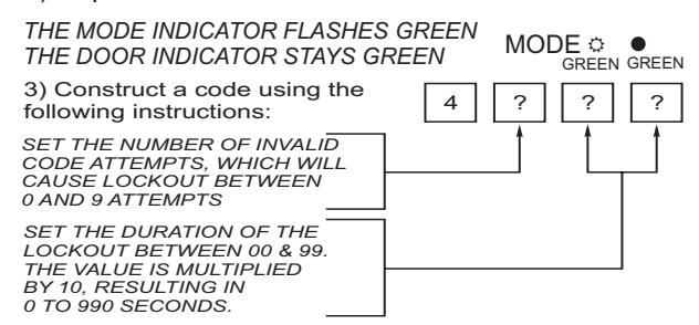
4) System returns to Normal Mode.
YOU WILL HEAR 3 BEEPS THE MODE INDICATOR TURNS GREEN MODE ● ○ DOOR THE DOOR INDICATOR TURNS OFF GREEN GREEN
4.10 BACKLIGHT AND LED BEHAVIOR
The keypad allows you to define the way the keypad's backlight will work, as well as the Mode and Door Indicator LED's.
To define the backlight and LED's operation:
- 1) Enter the Programming Mode.
- 2) Depress -6- to enter Menu 6.
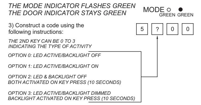
4) System returns to Normal Mode.
YOU WILL HEAR 3 BEEPS THE MODE INDICATOR TURNS GREEN MODE ● ○ DOOR THE DOOR INDICATOR TURNS OFF GREEN
4) System returns to Normal Mode.
GREEN MODE DOOR YOU WILL HEAR 3 BEEPS THE MODE INDICATOR TURNS GREEN THE DOOR INDICATOR TURNS OFF
4.11 ENROLLING CODES
4.11.1 Primary Codes Definition
- • Primary Codes can only be enrolled to an empty user slot. A slot with no existing Primary Code in the keypad's memory.
- • A Primary Code must be unique, for instance, one user's Primary Code can not be the same as that of another user.
- • Primary Codes can not be the same as system codes, such as the Normal/Secure Code and the Open Code.
- • User's possessing a Primary Code can gain entry during Normal and Bypass Mode.
4.11.2 Secondary Codes Definition
- • Secondary Codes can only be enrolled to a user slot that already has a Primary Code.
- • A Secondary Code does not need to be unique, for instance, one user's Secondary Code can be the same as another user's.
- • Secondary Codes can not be the same as any system codes, such as Normal/Secure Code or the Open Code.
- • User's possessing Secondary Codes can gain entry in any mode of operation.
- • A Secondary Code can be the same as a Primary Code of any user.
4.11.3 Primary and Secondary Codes Enrolling Methods
There are two methods used to enroll Primary and Secondary Codes: The Standard Method and the Code Search Method.
- 1) The Standard Method is used when the user slot number, for the user you wish to program, is known. You can program both Primary and Secondary Codes using this method.
- 2) The Code Search Method is mainly used when enrolling a Secondary Code and the user slot code is unknown. The Code Search Method will function only if a user's Primary Code is already enrolled and if the Secondary Code is not.
4.11.4 Standard Method for Code Enrolling
- 1) Enter the Programming Mode.
- 2) Depress -7- to enter Menu.
ORANGE THE DOOR INDICATOR TURNS ORANGE MODE DOOR
3) Enter the 3 digit user slot number into memory (from 001 to 500) to enroll a Primary or Secondary code.
FOR EXAMPLE: THE USER SLOT 003 REPRESENTS USER NUMBER 3
4) At this time 3 possibilities exist:
A) IF THE SELECTED SLOT HAS NO PRIMARY CODE, THE MODE INDICATOR WILL FLASH GREEN, INDICATING THE GREEN ORANGE KEYPAD IS READY TO ACCEPT A PRIMARY CODE
B) IF THE SELECTED SLOT ALREADY HAS A PRIMARY CODE, BUT NO SECONDARY, THE MODE INDICATOR WILL FLASH RED, INDICATING THE KEYPAD IS READY TO ACCEPT A SECONDARY CODE
MODE
C) IF THE SELECTED SLOT ALREADY HAS A PRIMARY AND SECONDARY CODE, A LONG BEEP WILL BE HEARD AND THE KEYPAD WILL RETURN TO NORMAL MODE
Enter the code to be assigned for that slot number.
If the code that is entered is valid, the Mode Indicator LED will cease flashing and the keypad is ready for the next 3 digit slot numbers (step 3) or depress the # key to move to the next slot number (step 4). If you don't want to continue enrolling codes, depress the # key TWICE in recession and the keypad will return to its Normal Mode.
4.11.5 Search Method for Code Enrolling
The Code Search Method enables you to quickly enroll a Secondary Code for a user whose Primary Code is known but the slot number is unknown
ORANGE
- 1) Enter the Programming Mode.
- 2) Depress -7- to enter Menu.
THE DOOR INDICATOR TURNS ORANGE ORANGE MODE DOOR
3) Enter 000
MODE DOOR THE DOOR INDICATOR FLASHES ORANGE YOU CAN NOW ENTER A USERS PRIMARY CODE
4) Enter the user's Primary Code.
THE MODE INDICATOR FLASHES RED THE DOOR INDICATOR FLASHES ORANGE ORANGE MODE DOOR RED
IF THE PRIMARY CODE ENTERED IS NOT VALID, A LONG BEEP WILL SOUND AND THE KEYPAD WILL WAIT FOR A VALID PRIMARY CODE
5) Enter the code to be used as the Secondary Code. If the code is valid, the keypad will beep 3 times and return to Normal Mode.
IF THE SECONDARY CODE IS NOT VALID, A LONG BEEP WILL SOUND AND THE KEYPAD WILL WAIT FOR A VALID SECONDARY CODE TO BE ENTERED
4.12 DELETING CODES
There are two methods to delete Primary and Secondary Codes:
- 1) The Standard Method
- 2) The Search Method
When deleting a user slot, both the Primary and the Secondary Codes are erased.

• It is recommended that a record be kept of added and deleted user's. This will make it easier to keep track of user slots' status (empty or not).
4.12.1 Standard Method for Deleting Codes
- 1) Enter the Programming Mode.
- 2) Depress -8- to enter Menu 8.
THE MODE INDICATOR TURNS RED THE DOOR INDICATOR TURNS ORANGE ORANGE
MODE DOOR RED
3) Enter the 3 digit user slot to be deleted.
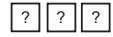
THE MODE INDICATOR FLASHES RED, INDICATING THE KEYPAD IS WAITING FOR A PROGRAMMING CODE TO CONFIRM DELETION ORANGE MODE DOOR RED
IF THE USER SLOT IS EMPTY, A LONG BEEP WILL BE HEARD AND THE KEYPAD RETURNS TO NORMAL MODE
4) Enter your Programming Code to confirm the deletion. If the Programming Code is valid, 3 beeps will be heard and the keypad will return to Normal Mode. If the Programming Code is invalid, a long beep will be heard and the keypad returns to Normal Mode.
4.12.2 Search Method for Deleting Codes
- 1) Enter the Programming Mode.
- 2) Depress -8- to enter Menu 8.
THE MODE INDICATOR TURNS RED THE DOOR INDICATOR TURNS ORANGE
MODE ● DOOR RED ORANGE
3) Enter the 000.
0 0 0
THE MODE INDICATOR STAYS RED, THE DOOR INDICATOR FLASHES ORANGE THE KEYPAD IS NOW WAITING FOR THE PRIMARY USER TO BE DELETED
4) Enter the users Primary code.
THE MODE INDICATOR FLASHES RED THE DOOR INDICATOR FLASHES ORANGE MODE & DOOR
5) Enter your Programming Code to confirm the deletion. If the Programming Code is valid, 3 beeps will be heard and the keypad will return to Normal Mode. If the Programming Code is invalid, a long beep will be heard and the keypad will return to Normal Mode.
4.13 RELAY CODE ASSIGNMENT
When a Primary Code is enrolled for any user, the user is authorized to activate the lock relay. However, different user codes may be set to operate the auxiliary relay instead or operate both the lock and auxiliary relay. Assignment of such codes is achievable for any valid user code entered in the keypad.
There are two methods to assign Relay Codes to user's:
- 1) The Standard Method
- 2) The Search Method
4.13.1 Relay Code Assignment using Standard Method
- 1) Enter the Programming Mode.
- 2) Depress -9- to enter Menu 9.
THE MODE INDICATOR TURNS GREEN THE DOOR INDICATOR TURNS ORANGE
MODE ● DOOR GREENORANGE
3) Enter the 3 digit user slot for code assignment.
? ? ?
THE MODE INDICATOR FLASHES GREEN THE DOOR INDICATOR STAYS ORANGE
MODE ☼ ● DOOR GREEN ORANGE
4) Enter the assignment digit for that user slot:
Depress 1: Activate the Lock relay only
Depress 2: Activate the auxiliary relay only
Depress 3: Activate BOTH relays
IF THE ASSIGNMENT CODE IS VALID, THE MODE INDICATOR WILL STOP FLASHING AND STAY GREEN. THE DOOR INDICATOR GREEN ORANGE WILL STAY ORANGE
The keypad is now waiting for another user slot number. Depress the # key to move to the next slot or enter a new slot number. If you do not wish to continue, depress the # key TWICE in recession and the keypad will return to Normal Mode.
4.13.2 Relay Code Assignment using Search Method
- 1) Enter the Programming Mode.
- 2) Depress -9- to enter Menu 9.
THE MODE INDICATOR TURNS GREEN THE DOOR INDICATOR TURNS ORANGE
MODE ● DOOR GREENORANGE
3) Enter 000.
0 0 0
THE MODE INDICATOR STAYS GREEN THE DOOR INDICATOR FLASHES ORANGE GREEN ORANGE GREEN ORANGE
4) Enter the users Primary code.
THE MODE INDICATOR FLASHES GREEN MODE : DOOR THE DOOR INDICATOR FLASHES ORANGE GREEN ORANGE
5) Enter the assignment digit for that user slot:
Depress 1: Activate the Lock relay only
Depress 2: Activate the auxiliary relay only
Depress 3: Activate BOTH relays
IF THE ASSIGNMENT DIGIT IS VALID, 3 BEEPS WILL BE HEARD AND THE KEYPAD WILL RETURN TO NORMAL MODE. IF THE ASSIGNMENT DIGIT IS INVALID, A LONG BEEP WILL SOUND AND THE KEYPAD WILL WAIT FOR ANOTHER ASSIGNMENT DIGIT TO BE ENTERED
4.14 PIN CODE LENGTH/FACTORY DEFAULT SETTINGS

Note:
You must be very careful before using this command. Changing the PIN Code length will also erase the ENTIRE memory contents, including all the user and special codes, and return all codes to the factory default settings.
- 1) Enter the Programming Mode.
- 2) Select the desired PIN code length as follows:
- A) 00-Returns to factory defaults and sets a 4 digit code.
- B) 05-Returns to factory defaults and sets a 5 digit code.
- C) 06-Returns to factory defaults and sets a 6 digit code.
- D) 08-Returns to factory defaults and sets a 4-8 digit code.

Note
When choosing the 4-8 option, please note that you should either enter zeros before the code, or press pound at the end (for example if your code is 12345, either enter 00012345 or 12345#).
THE MODE INDICATOR FLASHES RED THE DOOR INDICATOR FLASHES RED
MODE O DOOR
Enter the Programming Code.
IF THE PROGRAMMING CODE IS VALID, ALL MEMORY WILL BE ERASED. YOU WILL HEAR 3 BEEPS AND THE KEYPAD WILL RETURN TO NORMAL MODE. IF THE PROGRAMMING CODE IS INVALID, YOU WILL HEAR A LONG BEEP AND THE KEYPAD WILL RETURN TO NORMAL MODE, WITHOUT ERASING THE MEMORY CONTENTS
4.15 REPLACING A PROGRAMMING CODE

- • The keypad must be in its Normal Mode for the procedure to work. Insure that the Mode Indicator LED is green before proceeding.
- 1) Remove power from the keypad.
- 2) Depress and hold the REX push button.
- 3) Re-apply power to the keypad with the REX push button depressed.
- 4) Release the REX push button.
- 5) You now have 15 seconds to program a new Programming Code into the keypad using the initial default code ( 1234 ), before the keypad reverts to the existing code.
THE DEFAULT CODE DEPENDS ON THE PIN LENGTH SELECTED REFER TO THE PROGRAMMING MENU ON PAGE 19
4.15 REPLACING A NORMAL/SECURE CODE

- • The keypad must be in its Secure Mode for the procedure to work. Insure that the Mode Indicator LED is red before proceeding.
- 1) Remove power from the keypad.
- 2) Depress and hold the REX push button.
- 3) Re-apply power to the keypad with the REX push button depressed.
- 4) Release the REX push button.
- 5) You now have 15 seconds to use the default Normal/Secure Code ( 3838 ) to return to Normal Mode. Once in Normal Mode, enter the Programming Mode to program a new Normal/Secure Code.
THE DEFAULT CODE DEPENDS ON THE PIN LENGTH SELECTED REFER TO THE PROGRAMMING MENU ON PAGE 19
Featuring

A lifetime warranty applies to all standard DynaLock products. Damaged products will be repaired or replaced at no charge. Non-standard electronic products, e.g. custom consoles, will be repaired, if possible, at no charge. Custom length housings and special finished products will be replaced only if factory defective. Charges may apply for products damaged from abuse or errors in installation. Products not subject to charges do not have to be returned by the original purchaser.
Please follow this simple procedure if a problem occurs:
Call one of DynaLock's technicians and explain the problem. Most problems can be resolved with a phone consultation.
If the problem is not solved simply request a return merchandise authorization (RMA) on our website.

DynaLock manufactures a full line of security hardware. Magnetic Locks Electric Dead Bolts Power Supplies Access/Egress Controls Accessories
Catalog available on request.
For product information or for technical assistants call 877-DYNALOCK Toll Free 860-582-4761 or email info@dynalock.com www.dynalock.com
Emergency technical assistants is available Monday-Friday 5pm to 8pm (EST)
Glen @ 860-637-2599 Will @ 860-637-2394