DynaLock 3101CTJ Gen II Wiring Instructions
Open the original PDF document
View PDF

3101C-TJ101 (GENERATION II)
(GENERATION II) DELAYED EGRESS LOCK WIRING INSTRUCTIONS
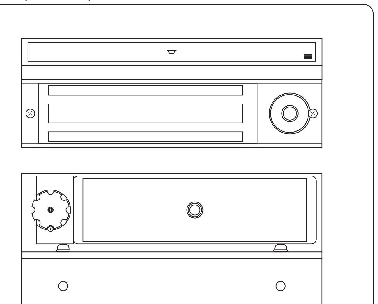

(GENERATION II) DELAYED EGRESS LOCK WIRING INSTRUCTIONS
BASIC SET-UP
1. Remove the Electronics Cover to expose the circuit board assembly.
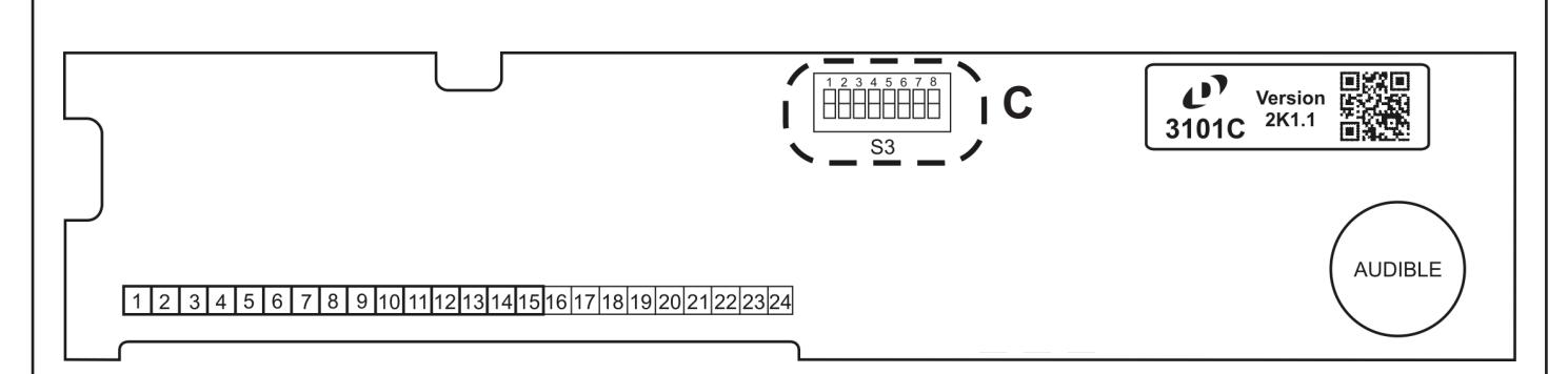
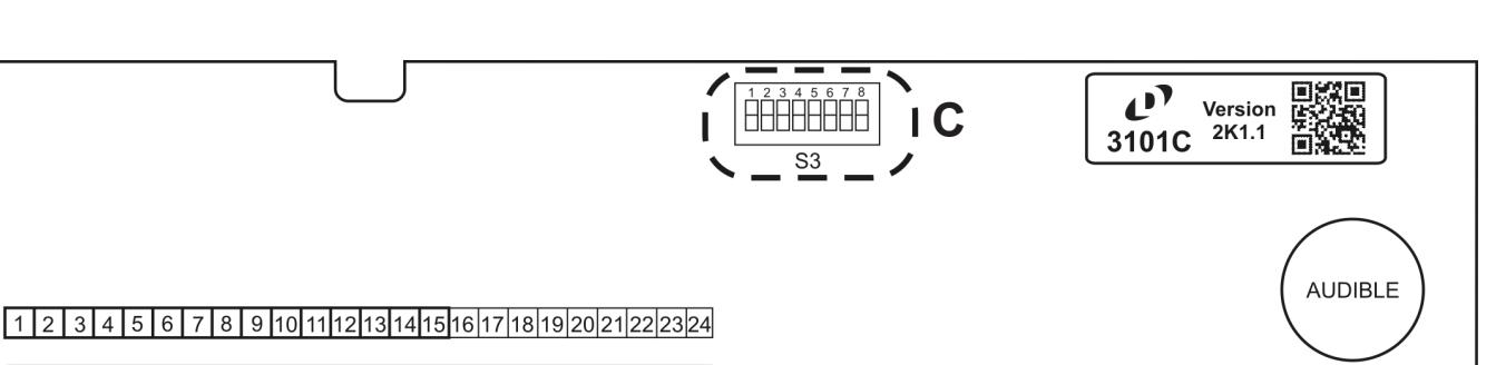
2. C - System Selector Switches
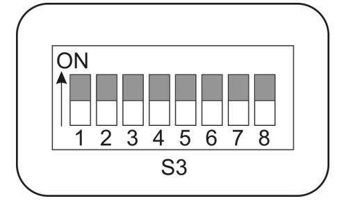
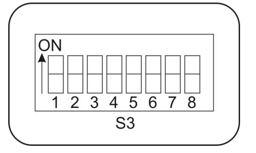
The selector switches (S3) which control major system functions are factory set to the OFF position for basic lock operation. Switch 1 will be used during sensor adjustment (page 8). Switches 2 through 7 are only used for options described on page 10.
(Factory Setting)

(GENERATION II) DELAYED EGRESS LOCK WIRING INSTRUCTIONS
BASIC WIRING
Basic hook-up is shown below. For other system features hook-up see "Option Wiring" (page 11).
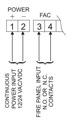
Terminals 1& 2 - Auto-Sensing Power Input. May be 12 or 24 Volts, AC or DC, uninterrupted. Maximum current draw, by voltage, is as follows:
12V DC: 456mA 12V AC: 1125mA 24V DC: 262mA 24V AC: 811mA
DO NOT INTERRUPT INPUT POWER (TERMINALS 1 & 2) FOR AUTHORIZED ACCESS/EGRESS. EXTERNAL ACCESS/EGRESS CONTROLS (EX. KEYPAD, CARD READER, ETC.) SHOULD USE DEDICATED BYPASS TERMINALS 7 & 8 or 9 & 10 (SEE PAGE 11).
Terminals 3 & 4 - Fire Panel Input. May be normally-open (N.O.) or normally-closed (N.C.) dry contacts from fire panel (check fire alarm control jumper "FA" - page 6). DO NOT APPLY POWER TO TERMINALS 3 & 4 OR CIRCUIT BOARD DAMAGE WILL OCCUR.
When the fire panel trips, the 3101C-TJ101 will release, the audible will sound a constant tone and the bi-color LED (LED1) will change to green. When the fire panel is reset, the 3101-TJ101 will reset and lock.
PROPER OPERATION OF THE 3101C REQUIRES ADJUSTMENT OF THE EGRESS SENSOR PROCEED TO EGRESS SENSOR ADJUSTMENT

1-877-DynaLock • www.dynalock.com
3101C-TJ101
(GENERATION II) DELAYED EGRESS LOCK WIRING INSTRUCTIONS
EGRESS SENSOR ADJUSTMENT
The sensor and armature assembly are designed for use on a door with existing mechanical latching hardware. If used on a door without a latch, false alarms are possible. In these cases, we suggest using an external trigger such as our 6451 Exit Sensor Bar - connect using terminals 11&12 and disable this internal sensor (see page 5).
SEE PAGE 5 FOR LOCATION OF ELECTRONIC PARTS MENTIONED IN THIS SECTION
- 1. With the door closed and latched apply input power to terminals 1 & 2. Slide selector switch (DS1) #1 to the ON position to activate the Set-Up mode. Rotate the on-board keyswitch counter-clockwise. The 3101C-TJ101 should now be unlocked (LED1-OFF).
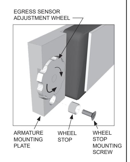
- 2. Open the door. Temporarily remove the Adjustment Wheel Stop from the Armature Mounting Plate and close the door. Set aside for re-installation later.
- 3. With the door closed observe the bi-color LED (LED1) on the circuit board. It should be lit red. If it is not lit, rotate the adjustment wheel counter-clockwise as necessary to ensure that it will contact and fully depress the ball plunger on the lock. Rattle the door to ensure the LED remains lit.
- 4. With the door closed and LED1 lit red, unlatch and slowly open the door. The LED will shut off as soon as the door opens far enough for the ball plunger to fully project.
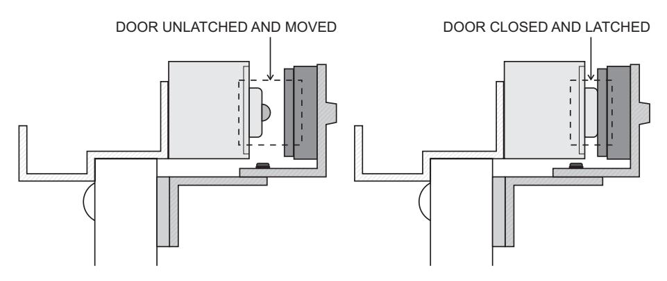
- 5. With adjustment completed, re-install the adjustment wheel stop to lock-in the adjustment. Close the door, slide selector switch (DS1) #1 back to the OFF position and return the on-board keyswitch to the center position to re-lock the 3101C-TJ101.
- 6. Unlatch and push on the door until delay egress triggers (1-3 seconds). The audible will sound and LED1 will flash red. After 15 seconds the lock will release. Turn the on-board keyswitch clockwise to reset the lock. If delayed egress triggers too soon, or fails to trigger, re-adjust the sensor adjustment wheel for desired sensitivity.
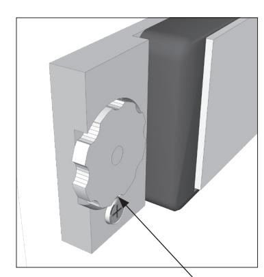
WHEEL STOP INSTALLED (LOCKS ADJUSTMENT)

3101C-TJ101 (GENERATION II)
(GENERATION II) DELAYED EGRESS LOCK WIRING INSTRUCTIONS
SEPERATE 7050 KEYSWITCH OPERATION
| POSITION | DESCRIPTION |
|---|---|
| CENTER | NORMAL / LOCKED |
| CLOCKWISE (SPRING LOADED) | RESET AFTER DELAY EGRESS ALARM |
| COUNTER-CLOCKWISE | BYPASS / UNLOCKED WITHOUT ALARM |
INDICATOR & AUDIBLE DESCRIPTIONS
| CONDITION | AUDIBLE SIGNAL | LOCK | 7054 KEYSWITCH |
|---|---|---|---|
| DELAY EGRESS ALARM | One second pulse rate during delay cycle. | ON | BLINK RED |
| DELAY EGRESS ALARM | Steady tone after delay until reset. | OFF | GREEN |
|
FIRE ALARM
RELEASE |
Steady tone until fire alarm contacts are reset. | OFF | GREEN |
|
OPTIONAL REMOTE
AUTHORIZED BYPASS (TERMINALS 7&8 / 9&10) |
None, unless bypass audible is enabled (dip switch 2). If door is held open past relock time, goes into delay egress alarm & requires reset. | OFF | BLINK GREEN |
|
POOR MAGNETIC
BOND |
Rapid pulse rate until problem is corrected (only functional with Dynastat Force Sensor option). | N/A | FAST BLINK RED |

(GENERATION II) DELAYED EGRESS LOCK WIRING INSTRUCTIONS
OPTIONAL SET-UP
1. C- System Selector Switches
Set the System Selector Switches (S3) to address your specific system requirements. The normal factory setting is all switches off.
| CMITCH | SWITCH FUNCTION | MODE SETTINGS | ||
|---|---|---|---|---|
| SWITCH | OFF | ON | ||
| 1 | SYSTEM SET-UP | NORMAL | SET-UP MODE | |
| 2 | BYPASS AUDIBLE * | DISABLED | ENABLED | |
| 3 | NUISANCE DELAY | 1 SEC. | 3 SEC. | |
| 4 | EGRESS DELAY | 15 SEC. | 30 SEC. | |
| 5 | MASTER AUDIBLE | ENABLED | DISABLED | |
| 6 |
FIRE ALARM
INPUT SETTING |
NORMALLY
OPEN |
NORMALLY
CLOSED |
|
| 7 | EGRESS SENSOR | ENABLED | DISABLED | |
| 8 | UNUSED SPARE | |||
* Only applies to terminals 9&10 (see next page)

(GENERATION II) DELAYED EGRESS LOCK WIRING INSTRUCTIONS
EXTERNAL MODEL 7054 KEY SWITCH CONNECTIONS
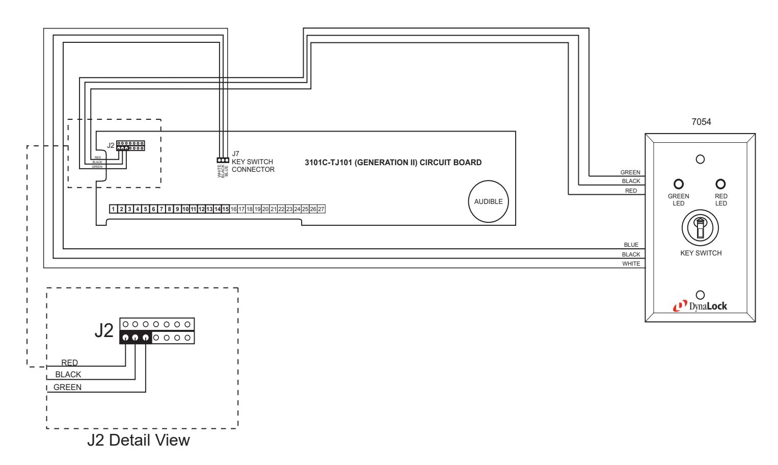
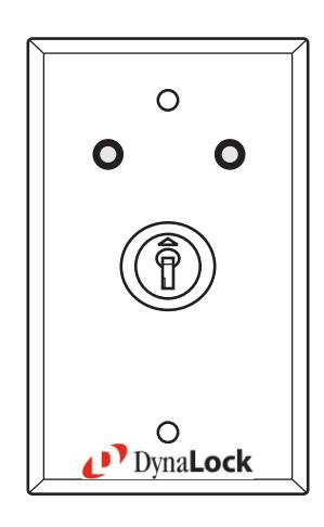
The external 7054 is included with the 3101C-TJ101 to provide reset and bypass functions to the maglock using the 7050's momentary / maintained key switch. The external 7054 also indicates lock status as well as door movement during egress sensor adjustment through the LEDs located on the 7054 faceplate.
The 3101C-TJ101 circuit board is supplied with flying lead connections for the 7054 key switch. These leads must be connected to match the same color flying leads coming from the 7054. ( See above illustration ).
Remember to observe polarity for either the key switch or LED's three wire harness. The key switch must be connected with the white wire facing the left (WHITE/BLACK/BLUE See above illustration). The 7054's LED connector must be seated with the red wire facing the left, on the lower left hand 3 pins of the J2 connector. (See detail view of J2 above).
Improper connection may result in damage to the 3101C-TJ101 circuit board.

1-877-DynaLock • www.dynalock.com
3101C-TJ101
(GENERATION II) DELAYED EGRESS LOCK
WIRING INSTRUCTIONS
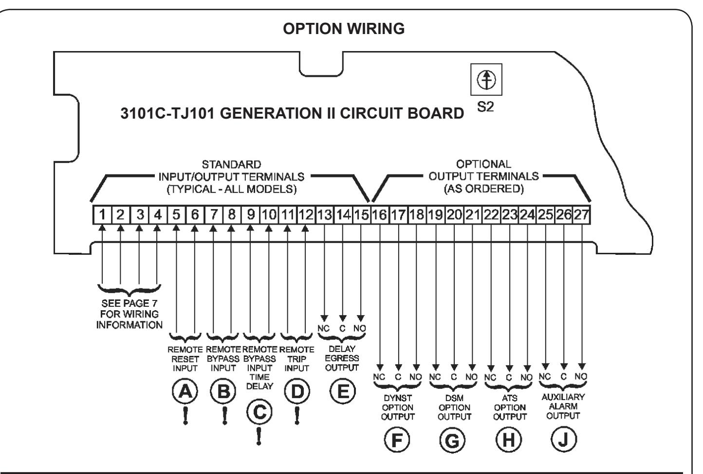
! WARNING: Do not apply power to inputs marked "!" or damage will occur.
INPUT DESCRIPTIONS
A) REMOTE RESET INPUT
Momentarily closing a normally-open dry contact across terminals 5 & 6 will reset and re-lock the 3101C following delayed egress and re-closure of door.

REMOTE BYPASS INPUT TIME DELAY
Momentarily closing a normally-open dry contact across terminals 9 & 10 will immediately release the lock without alarm. The door will remain unlocked for a period of time controlled by on-board adjustable timer S2. To increase the delay rotate timer S2 clockwise. Range is 1 to 75 seconds (~5 sec. per click). For NFPA101 applications, the remote bypass device time delay must be set for 0 seconds.

(B) REMOTE BYPASS INPUT
Momentarily closing a normally-open dry contact across terminals 7 & 8 will immediately release the lock without alarm. The door will remain unlocked until the contact is opened. Connect authorized access/egress control(s) here (typical).

REMOTE TRIP INPUT
Momentarily closing a normally-open dry contact across terminals 11 & 12 will initiate delayed egress. This input may be used as a redundant or substitute means of triggering delayed egress if built-in sensor initiation is not desired (see page 10, note 3).

3101C-TJ101 (GENERATION II) DELAYED EGRESS LOCK WIRING INSTRUCTIONS
OPTION WIRING
| MONITORING OUTPUT DESCRIPTIONS | TYPICAL WIRING | ||
|---|---|---|---|
| DELAY EGRESS OUTPUT Delay egress alarm monitoring. SPDT dry relay contacts rated 1A @ 24VDC/24VAC Contacts change state upon initiation of delayed egress, after the nuisance delay has elapsed. They remain in that state until door is closed and reset. | ALARM (+) TO INDICATOR POWER SUPPLY SECURE NOTE: INDICATORS ARE NOT INCLUDED | ||
| F DYNST OPTION OUTPUT Dynastat bond sensor monitoring. SPDT dry relay contacts rated 1A @ 24VDC/24VAC Contacts change state to signal lock status as either secure or unsecure. Armature misalignment can also create an unsecure condition. | NC C NO 16 17 18 UNSECURE H POWER SUPPLY SECURE NOTE: INDICATOR ARE NOT INCLUDED | ||
| G DSM OPTION OUTPUT Door position sensor monitoring. SPDT dry relay contacts rated 0.5A @ 24VDC Contacts change state to signal physical door position as either closed or open. DSM is an independent circuit that does not require lock power to operate. | OPEN (+) TO INDICATOR POWER SUPPLY CLOSED NOTE: INDICATORS ARE NOT INCLUDED | ||
| ATS OPTION OUTPUT Anti-Tamper Switch monitoring. SPDT dry relay contacts rated 0.25A @ 24VDC Contacts change state to signal removal of the lock electronics cover. | TAMPER (+) TO INDICATOR POWER SUPPLY NORMAL NOTE: INDICATORS ARE NOT INCLUDED | ||
| AAO AUXILIARY ALARM OUTPUT Secondary delay egress alarm monitoring output. SPDT dry relay contacts rated 1A @ 24VDC/24VAC Contacts change state upon initiation of delayed egress, after the nuisance delay has elapsed. They remain in that state until door is closed and reset. | ALARM (+) TO INDICATOR POWER SUPPLY SECURE NOTE: INDICATORS ARE NOT INCLUDED | ||

(GENERATION II) DELAYED EGRESS LOCK WIRING INSTRUCTIONS
FACTORY WIRING
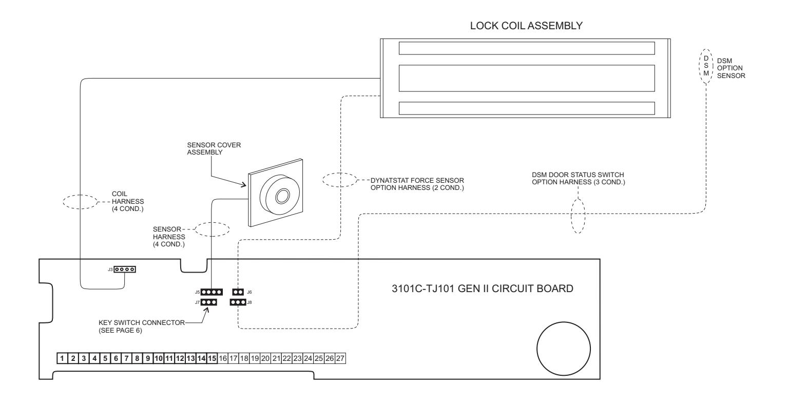
NOTES:
- 1. Harnesses J6 and J8 are only present if the 3101C-TJ101 Generation II is equipped with the DYN Dynastat Force Sensor and/or DSM Door Status Switch Options.
-
2. Observe polarity when re-connecting the J5 and J8 harness connectors. Orient these connectors with respect to harness wire colors as follows:
- J5 WHT GRN RED BLK J8 GRN WHT RED
- 3. Harness connectors J3 and J6 are not polarity sensitive.

3101C-TJ101 (GENERATION II) DELAYED EGRESS LOCK WIRING INSTRUCTIONS
| INSTALLER NOTES | |
|---|---|
| _ | |
| _ | |
| _ | |
| _ | |
| _ | |
| - | |
| _ | |
| _ | |
| _ | |
| _ | |
| - | |
| _ | |
| _ |
PLEASE DELIVER THIS MANUAL AND THE KEYS TO THE END USER UPON COMPLETION OF THE 3101C-TJ101 INSTALLATION
FOR PRODUCT SUPPORT AND PARTS ORDERING INFORMATION CONTACT:
DynaLock Corp. 705 Emmett Street Bristol, CT 06010
Bus: (877) 396-2562 Toll-Free USA
(860) 582-4761 Fax: (860) 585-0338
DYNALOCK ON THE INTERNET:
E-mail: info@dynalock.com Website: www.dynalock.com