DynaLock 3101C-ETR Installation Instructions
Open the original PDF document
View PDF

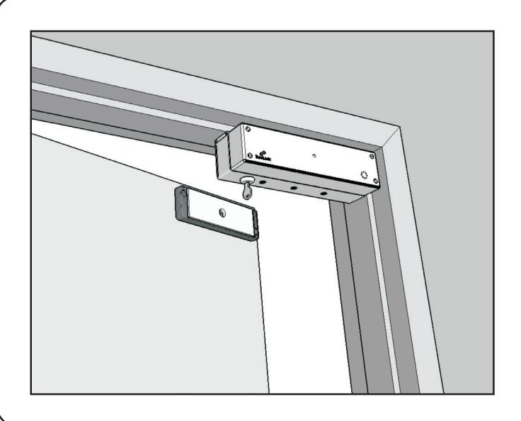
INSTALLATION DESCRIPTION
The 3101C-ETR Delay Egress System is a 1500 pound holding force (holding force not evaluated by UL) electromagnetic lock electronically controlled to provide a 15 or 30 second delay in unlocking.
Delayed egress is activated by an external dry contact closure, usually provided by a switch located in an exit device.
The 3101C-ETR requires both mechanical and electrical installation procedures as described herein.
HANDLING
The electromagnetic lock and armature are ruggedly constructed and designed to provide years of trouble-free service. Care must be taken during installation and use, so that the lock face and armature face are kept free of dirt, rust, paint, or any other obstruction which may interfere with the lock and armature making good contact.
MECHANICAL INSTALLATION
Familiarize yourself with the door and frame conditions. The lock must mount rigidly to the underside of the door frame header and against the vertical strike jamb. The door mounted armature is supplied with hardware that allows it to pivot slightly and pull away from the door as part of the delayed egress function.
NOTE: This lock does not change hands to match the hand of the door. Do not remove the coil assembly from the lock housing.
NOTE: For locks ordered with the DSM option, please verify that two magnets are installed inside the armature housing.
ELECTRICAL INSTALLATION
After mechanical installation is complete the 3101C-ETR needs to be wired and adjusted. A continuous power source, 12 or 24 VDC or VAC is required. Once low voltage power is supplied the unit is fully operational. Delay egress systems also normally require fire panel tie-in. All other wiring is for selected options.

3101C-ETR DELAYED EGRESS LOCK
INSTALLATION INSTRUCTIONS
TABLE OF CONTENTS
| General Information | 1 |
|---|---|
| Bill Of Materials | 2 |
| Using The Template | 3 |
| Mounting The Armature Assembly | 4 |
| Mounting The Lock | 5 |
| Basic Set-Up | 6 |
| Basic Wiring | 7 |
| Keyswitch Operation & Indicator Descriptions | 8 |
| Optional Set-Up | 9 |
| Option Wiring | 10-11 |
| Factory Wiring | 12 |
| Exploded Parts View | 13-14 |
| Installation Notes | 15 |
REQUIRED TOOLS
- (1) Electric Drill
- (1) #2 Phillips Screwdriver
- (1) Soft Faced Mallet
- (1) Hammer
- (1) Center Punch
- (1) Pencil & Tape
- Drill Bits: 1/8", 1/4", 17/64", 5/16", 3/8", 9/16", 21/32"
MODEL #3101C-ETR BILL OF MATERIALS
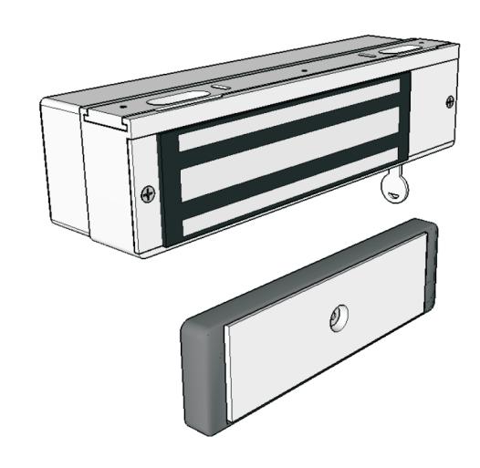
- (1) 3101C-ETR LOCK ASSEMBLY
- (1) ARMATURE
- (1) ARMATURE HOUSING
- (1) HARDWARE KIT
- (1) DOOR SIGN "15 SECONDS" *
- (1) TEMPLATE
- (1) INSTALLATION MANUAL
HARDWARE KIT CONTENTS (PN 301326)
QTY. ITEM DESCRIPTION #10 x 1" phillips pan head tek screw (5) Fas-Trak Mounting Screws 10-24 x 1/2" phillips pan head machine screw Fas-Trak Mounting Screws (5) Armature Mounting Screw 5/16-18 x 2" hex flat head machine screw, turned (1) (1) Armature Spacer 3/8"D x 0.235"L Door Spacer 5/8"D x 1-11/16"L spacer (1) (1) Sex Nut 5/16-18 sex nut Steel Washer 1/4" flat steel washer (1) 8-32 x 3/8" phillips flat head machine screw Armature Housing Mounting Screws (4) (4) Armature Housing Mounting Screws #8 x 1" phillips flat head sheet medal screw Anti-Tamper Cover Screwdriver #6 spanner kev (1) Fas-Trak Set Screw Wrench 1/8" ball head hex wrench (1) (1) Armature Bolt Wrench 3/16" hex wrench Bypass/Reset Key (2) (1) Mini Screwdriver
NOTE: For further parts clarification refer to the Exploded Parts View on page 13 or consult factory.
* & quot;30 SECONDS" SIGN AVAILABLE

MOUNTING CONSIDERATIONS
Inspect the door frame and determine if an angle bracket, spacer or filler plate will be required for installation. The lock will require a 2-9/16" wide header stop for a suitable mounting surface.
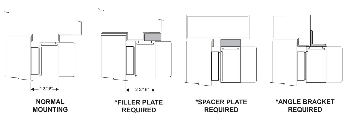
* These items are available from DynaLock.
USING THE TEMPLATE
- 1. Fold the template on the dotted line to form a 90 degree angle. Scoring the template with a straight edge and a screwdriver will make it fold easier.
- 2. With the door in the closed and latched position place the template against the header and door with one edge against the vertical strike jamb and tape in place.
- 3. Transfer all hole locations to both the door and header with a center punch, then remove the template from the door.
- 4. Referring to the template drill two 1/8" dia. lock mounting holes and one 9/16" dia. wiring hole in the top of the frame, at the transferred locations.
- CARDBOARD TEMPLATE OF DATE OF THE STORY OF THE STORY OF THE STORY OF THE STORY OF THE STORY OF THE STORY OF THE STORY OF THE STORY OF THE STORY OF THE STORY OF THE STORY OF THE STORY OF THE STORY OF THE STORY OF THE STORY OF THE STORY OF THE STORY OF THE STORY OF THE STORY OF THE STORY OF THE STORY OF THE STORY OF THE STORY OF THE STORY OF THE STORY OF THE STORY OF THE STORY OF THE STORY OF THE STORY OF THE STORY OF THE STORY OF THE STORY OF THE STORY OF THE STORY OF THE STORY OF THE STORY OF THE STORY OF THE STORY OF THE STORY OF THE STORY OF THE STORY OF THE STORY OF THE STORY OF THE STORY OF THE STORY OF THE STORY OF THE STORY OF THE STORY OF THE STORY OF THE STORY OF THE STORY OF THE STORY OF THE STORY OF THE STORY OF THE STORY OF THE STORY OF THE STORY OF THE STORY OF THE STORY OF THE STORY OF THE STORY OF THE STORY OF THE STORY OF THE STORY OF THE STORY OF THE STORY OF THE STORY OF THE STORY OF THE STORY OF THE STORY OF THE STORY OF THE STORY OF THE STORY OF THE STORY OF THE STORY OF THE STORY OF THE STORY OF THE STORY OF THE STORY OF THE STORY OF THE STORY OF THE STORY OF THE STORY OF THE STORY OF THE STORY OF THE STORY OF THE STORY OF THE STORY OF THE STORY OF THE STORY OF THE STORY OF THE STORY OF THE STORY OF THE STORY OF THE STORY OF THE STORY OF THE STORY OF THE STORY OF THE STORY OF THE STORY OF THE STORY OF THE STORY OF THE STORY OF THE STORY OF THE STORY OF THE STORY OF THE STORY OF THE STORY OF THE STORY OF THE STORY OF THE STORY OF THE STORY OF THE STORY OF THE STORY OF THE STORY OF THE STORY OF THE STORY OF THE STORY OF THE STORY OF THE STORY OF THE STORY OF THE STORY OF THE STORY OF THE STORY OF THE STORY OF THE STORY OF THE STORY OF THE STORY OF THE STORY OF THE STORY OF THE STORY OF THE STORY OF THE STORY OF THE STORY OF THE STORY OF THE STORY OF THE STORY OF THE STORY OF THE STORY OF THE STORY OF THE STORY OF THE STORY OF THE STORY OF THE STORY OF THE STORY OF THE STORY OF THE STORY OF THE STORY OF THE STORY OF THE STORY OF THE STORY OF THE STORY OF THE STORY OF THE STORY OF THE STORY OF
- 5. Drill the remaining transferred holes in the face of the door to accept the Armature following the instructions on page 4, for your specific door type.

MOUNTING THE ARMATURE ASSEMBLY
From the three illustrations below select the one that resembles your door type and follow the instructions for drilling the Armature mounting screw hole.
GLASS AND ALUMINUM OR HOLLOW METAL DOOR
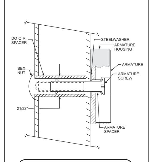
Drill an 3/8" diameter hole through the door. From the sex nut side only enlarge the 3/8" hole to 21/32" diameter.
SOLID CORE DOOR
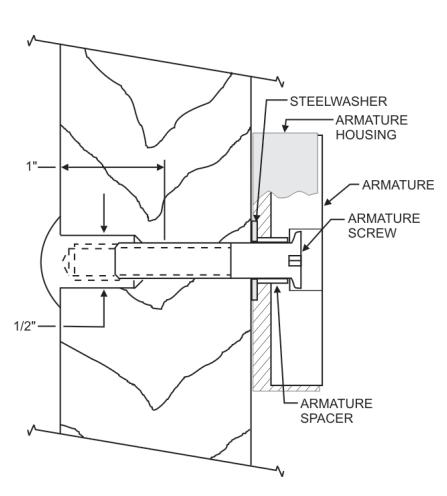
Drill an 3/8" diameter hole through the door. From the sex nut side drill 1/2" diameter hole to 1" depth.
REINFORCED DOOR
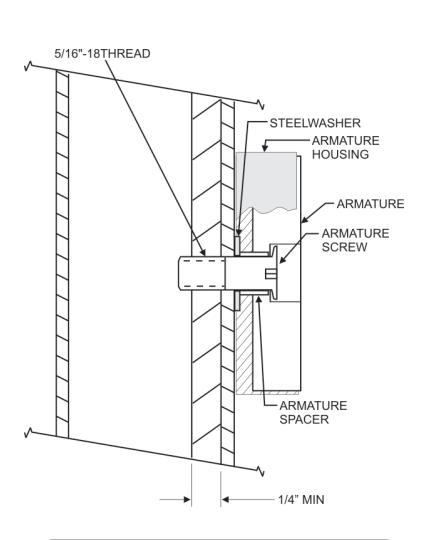
Drill a 17/64" diameter hole and tap for 5/16-18 thread
Mount the Armature Housing to the door using four (4) #8 x 1" sheet metal screws or #8-32 x 3/8" machine screws.
Place the Armature inside the Armature Housing and secure using the proper hardware, according to the above illustrations. Firmly tighten the Armature mounting screw with a 3/16" hex wrench.
Failure to properly secure the Armature to the door could result in serious injury or possible security breach.

MOUNTING THE LOCK
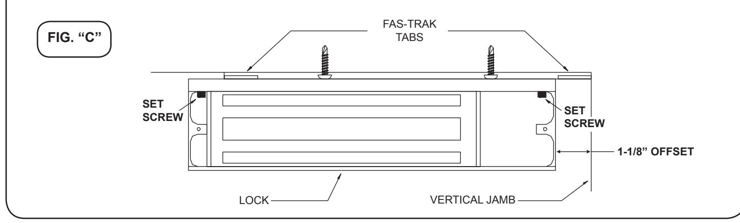
- Before installation begins remove the rear Electronics Cover, End Cover and Access (see page 14 for parts locations). In the upper inside corners of the lock housing are located two #1/4-28 set screws. Using the 1/8" ball head hex wrench loosen (do not remove) the two set screws until the Fas-Trak Baseplate is free (Fig. "C"). Remove the Fas-Trak.
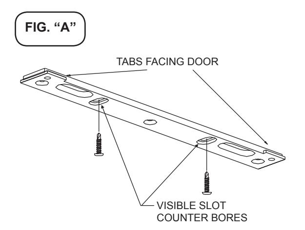
- 2. Place the Fas-Trak against the header with the slot counter bores visible and the tabs facing the door (Fig. "A"). Attach the Fas-Trak to the header at both slotted hole locations, with two #10 x 1" tek screws or 10-24x1/2" machine screws. Tighten the screws just snug enough to allow for final adjustment.
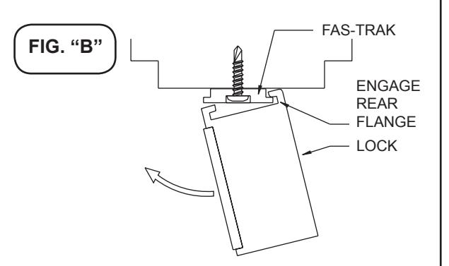
- 3. Temporarily mount the lock to the Fas-Trak by offsetting the lock 1-1/8" from the jamb (Fig. "C") and tipping the front of the lock down engaging the rear flange of the Fas-Trak (Fig. "B"). Rotate the lock up allowing one tab to pass through the corresponding notch in the top of the lock housing. Slide the lock into position. Close and latch the door. Check that the armature and lock faces make full contact. If any adjustment is required gently tap the housing with a soft mallet until full contact is achieved. Open the door, remove the lock from the Fas-Trak and tighten both slot screws. Drive three more screws into the header using the Fas-Trak as a physical template. Screw heads must not project above the Fas-Trak.
4. Any roughed-in wiring may be brought in at this time through the slotted wiring holes. Re-install the lock on the Fas-Trak. Firmly tighten both housing set screws with the 1/8" ball head hex wrench. Re-install the End Cover and Access Cover. If the lock wiring and set-up are not being done at this time replace the Electronics Cover and see that these instructions are left for the electrical installer.

BASIC SET-UP
1. Remove the Electronics Cover to expose the circuit board assembly.
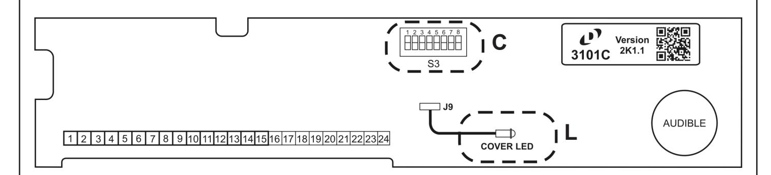
2. L - Cover LED
Bi-color LED, mounted to circuit board housing cover. Displays Red or Green, depending on lock mode (see page 9 for indicator modes). LED is tethered to the J9 circuit board connector, via a 30-wire harness. Should harness become unplugged, observe wire color polarity when reconnecting (see page 13 for further info).
3. C - System Selector Switches
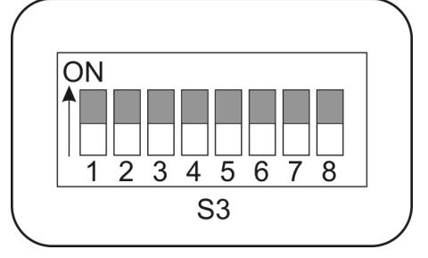
The selector switches (S3) which control major system functions are factory set to the OFF position for basic lock operation. Switch 1 will be used during sensor adjustment (page 8). Switches 2 through 7 are only used for options described on page 10.
(Factory Setting)

BASIC WIRING
Basic hook-up is shown below. For other system features hook-up see "Option Wiring" (page 11).
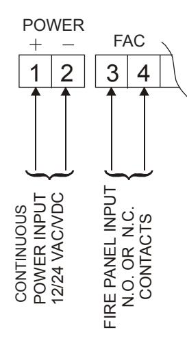
Terminals 1& 2 - Auto-Sensing Power Input. May be 12 or 24 Volts, AC or DC, uninterrupted. Maximum current draw, by voltage, is as follows:
12V DC: 453mA 12V AC: 1.08A 24V DC: 254mA 24V AC: 750mA
DO NOT INTERRUPT INPUT POWER (TERMINALS 1 & 2) FOR AUTHORIZED ACCESS/EGRESS. EXTERNAL ACCESS/EGRESS CONTROLS (EX. KEYPAD, CARD READER, ETC.) SHOULD USE DEDICATED BYPASS TERMINALS 7 & 8 or 9 & 10 (SEE PAGE 11).
Terminals 3 & 4 - Fire Panel Input. May be normally-open (N.O.) or normally-closed (N.C.) dry contacts from fire panel (check fire alarm control jumper "FA" - page 6). DO NOT APPLY POWER TO TERMINALS 3 & 4 OR CIRCUIT BOARD DAMAGE WILL OCCUR.
When the fire panel trips, the 3101B will release, the audible will sound a constant tone and the bi-color LED (LED1) will change to green. When the fire panel is reset, the 3101B will reset and lock.
NOTES:
- 1. A power limited, UL Listed power supply for security applications is required for UL294 installations.
- 2. When the 3101C is used with a fire alarm control panel, wiring must be done for fail-safe operation.
- 3. Suitability of all wiring leads is to be determined based on enduser product requirements.
PROPER OPERATION OF THE 3101C REQUIRES ADJUSTMENT OF THE EGRESS SENSOR PROCEED TO EGRESS SENSOR ADJUSTMENT

BUILT-IN KEYSWITCH OPERATION
| POSITION | DESCRIPTION |
|---|---|
| CENTER | NORMAL / LOCKED |
| CLOCKWISE (SPRING LOADED) | RESET AFTER DELAY EGRESS ALARM |
| COUNTER-CLOCKWISE | BYPASS / UNLOCKED WITHOUT ALARM |
INDICATOR & AUDIBLE DESCRIPTIONS
| CONDITION | AUDIBLE SIGNAL | LOCK | COVER LED |
|---|---|---|---|
| DELAY EGRESS ALARM | One second pulse rate during delay cycle. | ON | BLINK RED |
| DELAY EGRESS ALARM | Steady tone after delay until reset. | OFF | GREEN |
|
FIRE ALARM
RELEASE |
Steady tone until fire alarm contacts are reset. | OFF | GREEN |
|
OPTIONAL REMOTE
AUTHORIZED BYPASS (TERMINALS 7&8 / 9&10) |
None, unless bypass audible is enabled (dip switch 2). If door is held open past relock time, goes into delay egress alarm & requires reset. | OFF | BLINK GREEN |
|
POOR MAGNETIC
BOND |
Rapid pulse rate until problem is corrected (only functional with Dynastat Force Sensor option). | N/A | FAST BLINK RED |

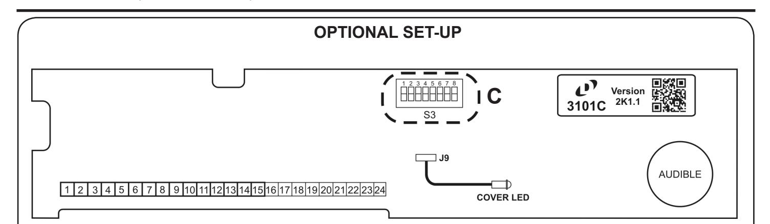
1. C- System Selector Switches
Set the System Selector Switches (S3) to address your specific system requirements. The normal factory setting is switches 1 through 6 and switch 7 ON.
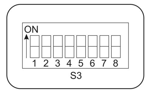
| OMITOLI | MODE | SETTINGS | |
|---|---|---|---|
| SWITCH | FUNCTION | OFF | ON |
| 1 | SYSTEM SET-UP | NORMAL | SET-UP MODE |
| 2 | BYPASS AUDIBLE * | DISABLED | ENABLED |
| 3 | NUISANCE DELAY | 1 SEC. | 3 SEC. |
| 4 | EGRESS DELAY | 15 SEC. | 30 SEC. |
| 5 | MASTER AUDIBLE | ENABLED | DISABLED |
| 6 |
FIRE ALARM
INPUT SETTING |
NORMALLY
OPEN |
NORMALLY
CLOSED |
| 7 | EGRESS SENSOR | ENABLED | DISABLED |
| 8 | UNUSED SPARE |
* Only applies to terminals 9&10 (see next page)

1-877-DynaLock • www.dynalock.com
3101C-ETR DELAYED EGRESS LOCK INSTALLATION INSTRUCTIONS
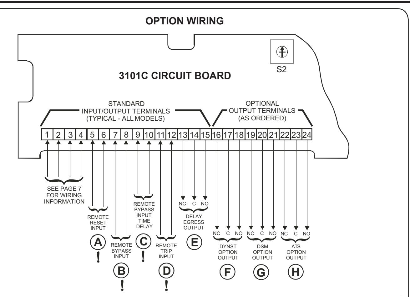
! WARNING: Do not apply power to inputs marked "!" or damage will occur.
Per UL294 installlations, all wiring must interconnect to equipment in the same room.
INPUT DESCRIPTIONS
A) REMOTE RESET INPUT
Momentarily closing a normally-open dry contact across terminals 5 & 6 will reset and re-lock the 3101C following delayed egress and re-closure of door.

(C) REMOTE BYPASS INPUT TIME DELAY
Momentarily closing a normally-open dry contact across terminals 9 & 10 will immediately release the lock without alarm. The door will remain unlocked for a period of time controlled by on-board adjustable timer S2. To increase the delay rotate timer S2 clockwise. Range is 1 to 75 seconds (~5 sec. per click). For NFPA101 applications, the remote bypass device time delay must be set for 0 seconds.

(B) REMOTE BYPASS INPUT
Momentarily closing a normally-open dry contact across terminals 7 & 8 will immediately release the lock without alarm. The door will remain unlocked until the contact is opened. Connect authorized access/egress control(s) here (typical).

REMOTE TRIP INPUT
Momentarily closing a normally-open dry contact across terminals 11 & 12 will initiate delayed egress.

OPTION WIRING
MONITORING OUTPUT DESCRIPTIONS
(E) DELAY EGRESS OUTPUT
Delay egress alarm monitoring.
SPDT dry relay contacts rated 1A @ 24VDC/24VAC
Contacts change state upon initiation of delayed egress, after the nuisance delay has elapsed. They remain in that state until door is closed and reset.
TYPICAL WIRING
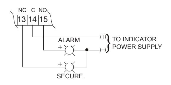
NOTE: INDICATORS ARE NOT INCLUDED
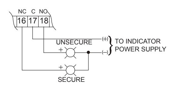
(F) DYNST OPTION OUTPUT
Dynastat bond sensor monitoring.
SPDT dry relay contacts rated 1A @ 24VDC/24VAC
Contacts change state to signal lock status as either secure or unsecure. Armature misalignment can also create an unsecure condition.
NOTE: INDICATORS ARE NOT INCLUDED
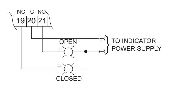
(G) DSM OPTION OUTPUT
Door position sensor monitoring.
SPDT dry relay contacts rated 0.5A @ 24VDC
Contacts change state to signal physical door position as either closed or open. DSM is an independent circuit that does not require lock power to operate.
NOTE: INDICATORS ARE NOT INCLUDED
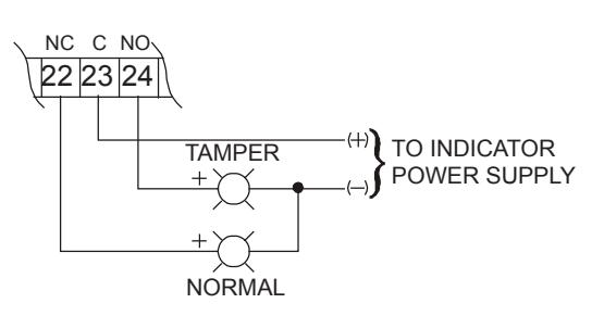
(H) ATS OPTION OUTPUT
Anti-Tamper Switch monitoring.
SPDT dry relay contacts rated 0.25A @ 24VDC
Contacts change state to signal removal of the lock electronics cover.
NOTE: INDICATORS ARE NOT INCLUDED

NOTES:
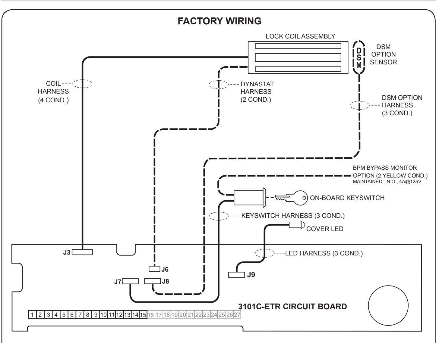
- 1. Harnesses J6 and J8 are only present if the 3101C-ETR is equipped with the DYN Dynastat Force Sensor and/or DSM Door Status Switch Options.
-
2. Observe polarity when re-connecting the J7, J8 and J9 harness connectors. Orient these connectors with respect to harness wire colors as follows:
- J7 WHT BLK BLU J8 GRN WHT RED J9 GRN BLK RED
- 3. Harness connectors J3 and J6 are not polarity sensitive.

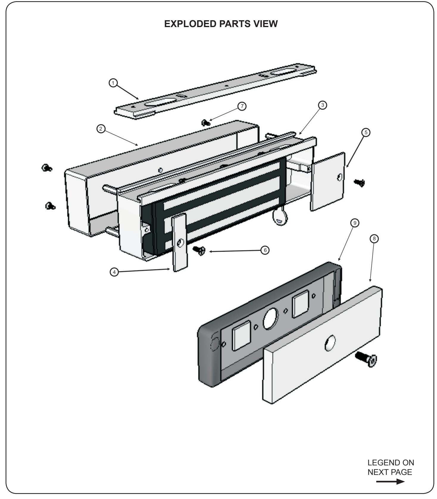

EXPLODED PARTS VIEW LEGEND
| LOCK ASSEMBLY | ||
|---|---|---|
| ITEM | DESCRIPTION | PART# |
| 1 | Fas-Trak Baseplate | 300011 |
| 2 | Electronics Cover | 300353 |
| 3 | Lock Assembly |
Consult
Factory |
| 4 | End Cover | 300011 |
| 5 | Access Cover | 300009 |
| 6 | Access/End Cover Screws | 300608 |
| 7 | Electronics Cover Screws | 700058 |
| 8 | Armature | 500373 |
| 9 | Armature Housing | 301244 |
| ETR HARDWARE KIT 301326 | ||
|---|---|---|
| 5 | Baseplate Mounting Screw | ***** |
| 5 | Baseplate Mounting Screw | ***** |
| 1 | Spacer Tube | ***** |
| 1 | Zinc Washer | ***** |
| 1 | Armature Mounting Screw | ***** |
| 1 | Keys (set) | ***** |
| 1 | Screwdriver | ***** |
| 1 | Snake Eye Screwdriver | ***** |
| 1 | 1/8 Hex Ball Wrench | ***** |
| 1 | Sex Nut | ***** |
| 1 | Spacer Tube | ***** |
| 4 | Armature Housing Mounting Screws | ***** |
| 4 | Armature Housing Mounting Screws | ***** |
| 1 | 3/16 Hex Key | ***** |

INSTALLATION NOTES Sketch in all field connections to external system devices specific to your installation, for future reference.
PLEASE DELIVER THIS MANUAL AND THE KEYS TO THE END USER UPON COMPLETION OF THE 3101C-ETR INSTALLATION
FOR PRODUCT SUPPORT AND PARTS ORDERING INFORMATION CONTACT:
DynaLock Corp. 705 Emmett Street Bristol, CT 06010
Bus: (877) 396-2562 Toll-Free USA
(860) 582-4761 Fax: (860) 585-0338
DYNALOCK ON THE INTERNET:
E-mail: info@dynalock.com Website: www.dynalock.com


SPECIAL LOCKING ARRANGEMENTS CATEGORY FWAX