DynaLock 2022-392 Installation Manual
Open the original PDF document
View PDF

INSTALLATION INSTRUCTIONS
INSTALLATION DESCRIPTION
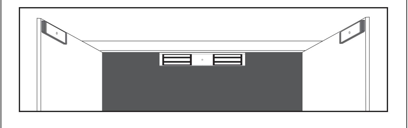
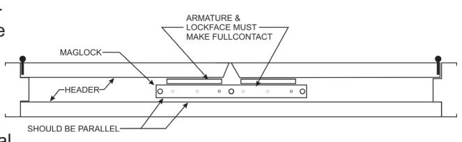
The series 2022-392 is a 1200 pound holding force electromagnetic lock designed to retro-fit a Locknetics 392 on a dual outswing door. The lock requires both installation procedures as described herein and in the wiring instructions included. Typical installation of the lock on a double outswing door shown below:
HANDLING
Care must be taken that the lock face and armature face are kept free of dirt, rust, paint, or any other obstruction which may interfere with the lock and armature making good contact. These faces may be cleaned with a non-abrasive pad and wiped with an oil dampened cloth.
MECHANICAL INSTALLATION
Familiarize yourself with the door and frame conditions. The lock must mount rigidly to the face of the door frame header. The door mounted armature is supplied with an adjustable mounting bracket and hardware that allows it to pivot slightly to compensate for reasonable misalignment.
NOTE: If this lock is supplied with the DSM2 option be certain that disc magnets are present inside each armature housing.
ELECTRICAL INSTALLATION
After mechanical installation is complete the lock needs to be wired to a 12 or 24 VDC/VAC power source. Once low voltage power is supplied the unit is fully operational. All other wiring is for selected options. Refer to the separate wiring instructions included for further information.

INSTALLATION INSTRUCTIONS
TABLE OF CONTENTS
| General Information | • |
|---|---|
| Bill Of Materials | |
| Using The Template | 3 |
| Mounting The Armature | |
| Mounting The Lock | ļ |
| Exploded Parts View | |
| Exploded Parts Legend | 7 |
| Support | 8 |
REQUIRED TOOLS
- (1) Electric Drill
- (1) #2 Phillips Screw Driver
- (1) Soft Faced Mallet
- (1) Hammer
- (1) Center Punch
- (1) 3/16" Hex Wrench
- (1) Pencil & Tape
- Drill Bits: 1/8", 17/64", 11/32", 1/2", 9/16", 21/32"
MODEL #2022-392 BILL OF MATERIALS
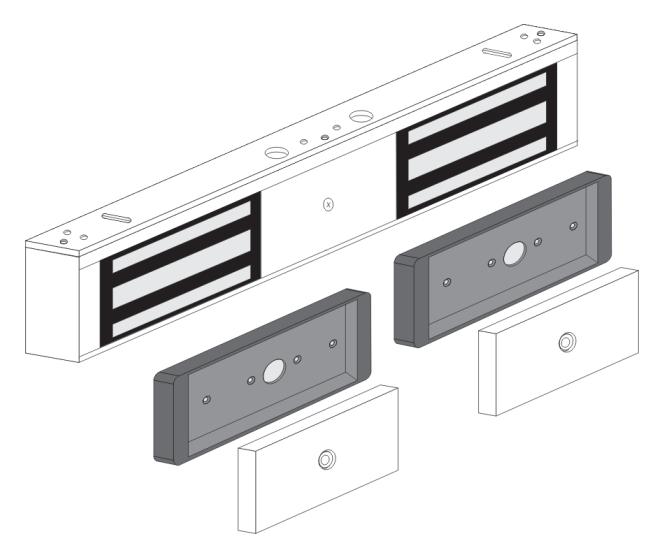
- (1) 2022-392 LOCK ASSEMBLY
- (2) ARMATURE
- (2) ARMATURE HOUSING
- (2) HARDWARE KIT
- (1) 3/16" SHORT ARM HEX WRENCH
- (1) MOUNTING TEMPLATE
- (1) INSTALLATION MANUAL
- (1) WIRING MANUAL
HARDWARE KIT CONTENTS PN# 301433 X2 PER LOCK
| QTY. | ITEM | DESCRIPTION | |
|---|---|---|---|
| 6 | Baseplate Mounting Screws | #10x1" phillips pan head sheet metal screw | |
| 6 | Baseplate Mounting Screws | #10-24x1/2" phillips pan head machine screw | |
| 1 | Armature Mounting Screw | 5/16-18x2" hex fat head machine screw, turned | |
| 4 | Armature Housing Screws | #8x1" phillips fat head sheet metal screw | |
| 4 | Armature Housing Screws | 8-32x3/8" phillips fat head machine screw | |
| 1 | Armature Spacer | 3/8"Dx0.235"L spacer | |
| 1 | Steel Washer | 1/4" fat steel washer | |
| 1 | Door Spacer | 5/8"Dx1-11/16"L spacer | |
| 1 | Sex Nut | 5/16-18 sex nut | |
| 3 | Plug Button | Plug Button 9/32" | |
NOTE: For further parts clarification refer to the Exploded Parts View on page 6 or consult factory.

INSTALLATION INSTRUCTIONS

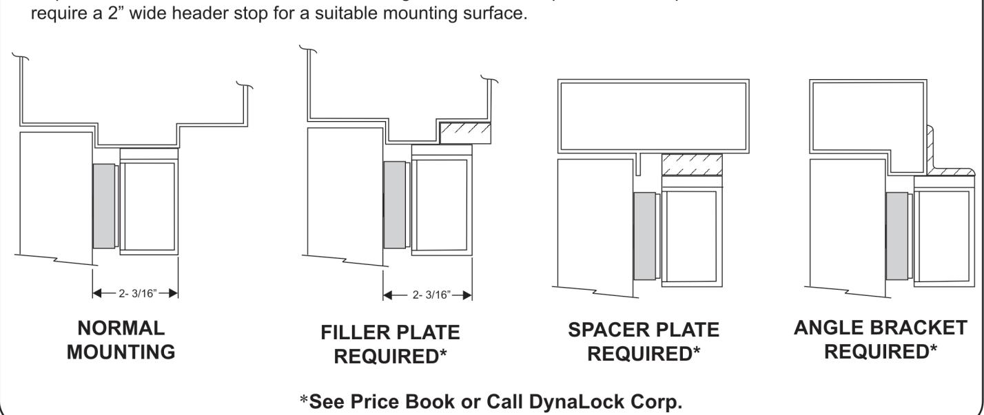
Inspect the door frame and determine if an angle bracket or fller plate will be required for installation. The lock will
USING THE TEMPLATE
- 1Fold the template on the dotted line to form a 90 degree angle. Scoring the template with a straight edge and a screwdriver will make it fold easier.
- 2. With the doors in the closed and latched position, from the push side, place the template against the header and doors in the center of the frame, and tape in place.
- 3. Transfer all hole locations to both the doors and header with a center punch, then remove the template from the door.
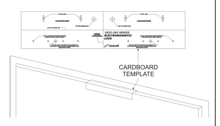
- 4. Referring to the template drill four 1/8" dia. lock mounting holes (or tap for 10-24) and one 9/16" dia. wiring hole in the top of the frame, at the transferred locations. Remaining mounting holes will be drilled after lock is frst mounted and adjusted (page 6).
- 5. Drill the remaining transferred holes in the face of the doors to accept the Armatures following the instructions on page 4 for your specifc door type.

INSTALLATION INSTRUCTIONS
MOUNTING THE ARMATURE
From the three illustrations below select the one that resembles your door type and follow the instructions for drilling the Armature mounting screw hole. (See Template)
Drill four (4) 1/8" dia. holes for #8 x 1" sheet metal screws or drill and tap for #8-32 x 3/8" machine screws (See Template).
GLASS AND ALUMINUM OR HOLLOW METAL DOOR
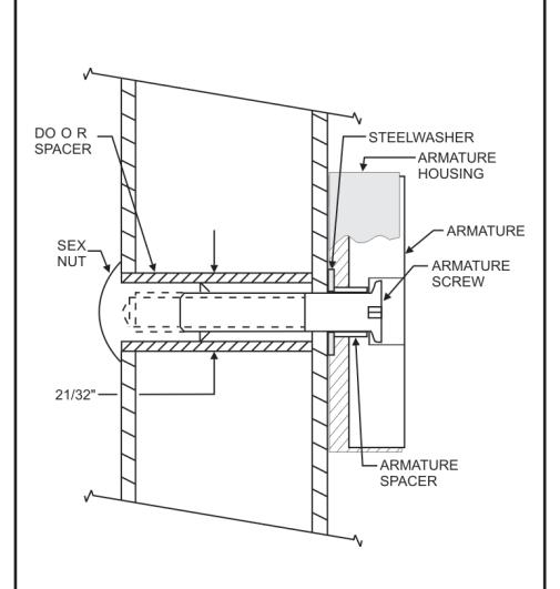
Drill an 11/32" diameter hole through the door. From the sex nut side only enlarge the hole to 21/32" diameter.
SOLID CORE DOOR
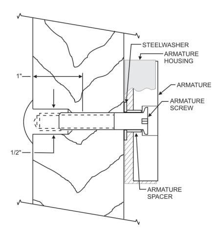
Drill an 11/32" diameter hole through the door. From the sex nut side drill 1/2" diameter hole to 1" depth.
REINFORCED DOOR
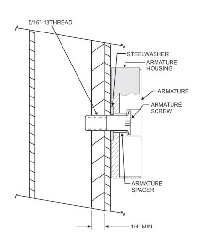
Drill a 17/64" diameter hole and tap for 5/16-18 thread
Mount the Armature Housing to each door using four (4) " sheet metal screws or " machine screws.
Place the Armature inside the Armature Housing and secure using the proper hardware, according to the above illustrations. Firmly tighten the Armature mounting screw with a 3/16" hex wrench.
Failure to properly secure the Armature to the door could result in serious injury or possible security breach.

INSTALLATION INSTRUCTIONS
MOUNTING THE LOCK
1) Mounting the baseplate to the header:
Separate the baseplate from the lock housing with the Hex wrenc Place the baseplate against the header with the counter sunk slot visible, and the large slot over the wire hole. Using an electric dril with a Philips bit attach the baseplate to the header at both slotter locations with the screws provided. Tighten the screws just snug enough to allow for final adjustments.
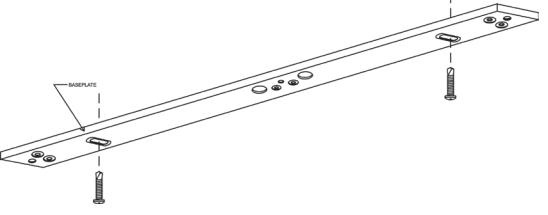
2) Aligning the lock and armature:
Close and latch the door. Temporarily mount the lock to the baseplate and verify the lock face and the armature are making full contact for the entire length of the armature. If any adjustment required gently tap the baseplate with a soft mallet until full contact is achieved. Mark the two baseplate corner locations lightly with a pencil for reference. Remove the lock from the baseplate and tighten both adjustment screws. Drive the remaining 4 screws into the header using the baseplate as a physical template. Screw heads must not project above the baseplate.
3) Attaching the lock to the baseplate:
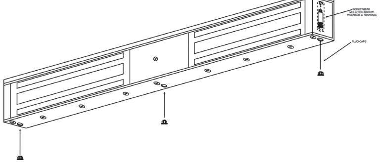
Using the Hex wrench, permanently fasten the lock to the baseplate with the three 1/4" - -1/4" machine screws removed in step 1. Install the plug caps over the mounting screws with a small mallet.

INSTALLATION INSTRUCTIONS

INSTALLATION INSTRUCTIONS
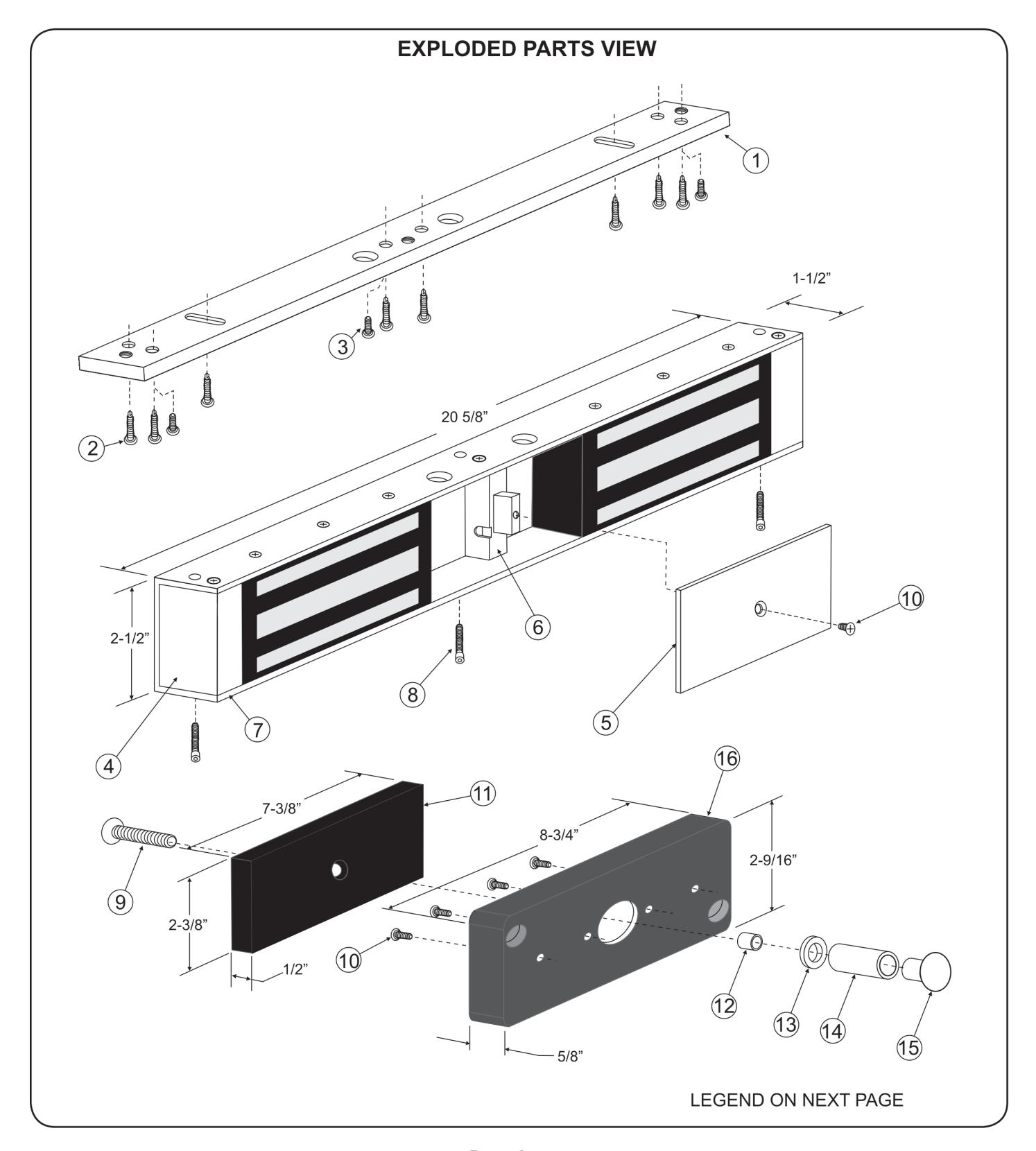
PARTS LEGEND
| ITEM | DESCRIPTION | PART# |
|---|---|---|
| 1 | MOUNTING BASEPLATE | 301491 |
| 2 | #10x1" SELF TAPPING SCREW | ***** |
| 3 | 10-24x1/2" MACHINE SCREW | ***** |
| 4 | END BLOCK | 301492 |
| 5 | ACCESS COVER | 301529 |
| 6 | CENTER BLOCK | 301493 |
| 7 | HOUSING | 301494 |
| 8 | Lock Mounting Bolt | 300603 |
| 9 | 5/16-18 ARM. SCREW TURNED | ***** |
| 10 | 8-32x3/8" MACHINE SCREW | ***** |
| 11 | ARMATURE | 300373 |
| 12 | ARMATURE SPACER | ***** |
| 13 | STEEL WASHER | ***** |
| 14 | DOOR SPACER TUBE | ***** |
| 15 | SEX NUT | ***** |
| 16 | ARMATURE HOUSING ASSEMBLY | 301334 |
****** Parts are located in hardware pack. Refer to Page 6 for parts locations.

INSTALLATION INSTRUCTIONS
PLEASE DELIVER THIS MANUAL TO THE END-USER UPON COMPLETION OF THE INSTALLATION
FOR PRODUCT SUPPORT AND PARTS ORDERING INFORMATION CONTACT:
DynaLock Corp. 705 Emmett Street Bristol, CT 06010
Bus: (877) 396-2562 Toll-Free
(860) 582-4761 Fax: (860) 585-0338
DYNALOCK ON THE INTERNET:
E-mail: info@dynalock.com Website: www.dynalock.com


NYC Mea #23-92-E GWXT Auxiliary Lock
Page 8 03/13