DynaLock 1700 Series Brochure
Open the original PDF document
View PDF

1 7 0 0 S e r i e s
F i r e - L a b e l e d E l e c t r i c S t r i k e s
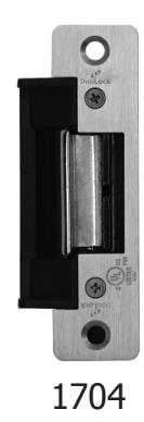
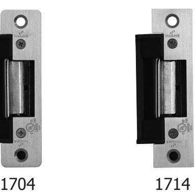


Description
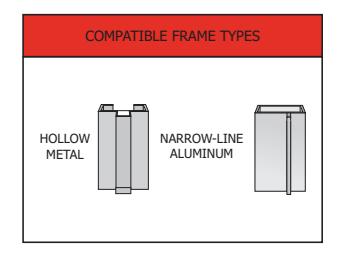
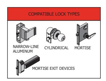
DynaLock 1700 Series Fire-Labeled Electric Strikes accommodate cylindrical, centerline mortise, and narrow-line aluminum locksets, along with mortise exit devices, with up to 3/4" latch projection (non-Pullman type). An enlarged latch cavity width allows compatibility with 3-piece, anti-friction latches. Fail-secure lock mode is standard and 12V and 24V models accept AC/DC input. All models are fully reversible for left or right-hand doors and standard mounting tabs and installation fasteners are included. Radius or square corner, US32D Stainless Steel, ANSI 4-7/8" x 1-1/4" faceplates are available. All models are Fire-Labeled, UL 10C (1-1/2 hr) and UL 1034 Burgulary-resistant.
Typical applications include fire rated doors in most commercial, industrial, institutional, retail, health care facilities and office complexes.
Standard Features
- Fire-Labeled UL10C (1-1/2Hr.)
- UL 1034 Burglary Resistant
- US32D Stainless Steel Face Plate
- Accommodates 3/4" Latch Projection (Non-Pullman)
- 12V and 24V Models Accept AC/DC Input
- Static Strength: 1,500Lbs
- Endurance Rating: 250,000 Cycles
- Great For Heavy-Duty Applications
- Non-Polarity Sensitive Coil
- Unique Anti-Vibration Design
- 3 Year Limited Warranty

1700 Series Fire-Labeled Electric Strikes Specifications
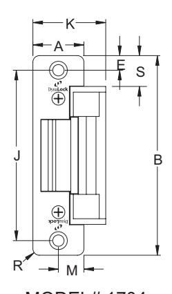
|
1704
INCHES |
1704
DECIMAL |
1704
METRIC (mm) |
|---|---|---|
| 1-1/4 | 1.250 | 31.75 |
| 4-7/8 | 4.875 | 123.83 |
| 3/8 | 0.375 | 9.53 |
| 4-1/8 | 4.125 | 104.78 |
| 1-3/4 | 1.750 | 44.45 |
| 5/8 | 0.625 | 15.88 |
| 5/32 | 0.156 | 3.97 |
| 3/4 | 0.750 | 19.05 |
|
1-1/4
4-7/8 3/8 4-1/8 1-3/4 5/8 |
INCHES DECIMAL 1-1/4 1.250 4-7/8 4.875 3/8 0.375 4-1/8 4.125 1-3/4 1.750 5/8 0.625 5/32 0.156 |
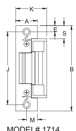
| PROFILE MEASUREMENT |
1714
INCHES |
1714
DECIMAL |
1714
METRIC (mm) |
|---|---|---|---|
| А | 1-1/4 | 1.250 | 31.75 |
| В | 4-7/8 | 4.875 | 123.83 |
| Е | 3/8 | 0.375 | 9.53 |
| J | 4-1/8 | 4.125 | 104.78 |
| K | 1-3/4 | 1.750 | 44.45 |
| М | 5/8 | 0.625 | 15.88 |
| R | N/A | N/A | N/A |
| S | 3/4 | 0.750 | 19.05 |
MODEL# 1704
MODEL# 1714
| MODEL | MODE | VOLTAGE | CURRENT | DUTY | SOUND | AMPS | OHMS |
|---|---|---|---|---|---|---|---|
| 17XX-12 | FAIL LOCKED | 12V | AC | INTERMITTENT | BUZZ | 0.15 | 61 |
| 12V | DC | CONTINUOUS | SILENT | 0.20 | 61 | ||
| 17XX-24 | FAIL LOCKED | 24V | AC | INTERMITTENT | BUZZ | 0.07 | 215 |
| 24V | DC | CONTINUOUS | SILENT | 0.11 | 215 |
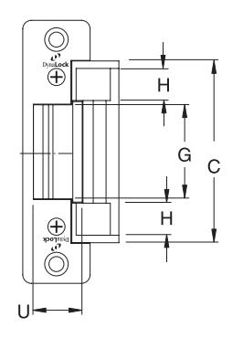
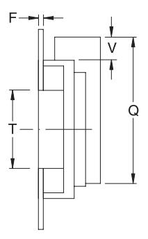
*Ratings are based on maximum current draw at +10°C and include initial power-up current draw. Nominal resistance at +25°C ± % tolerance. NOTE: XX = Faceplate Code. Intermittent Duty = Energized less than 1 min. Continuous Duty = Energized 1 min. or more. Duty Ratio 1:5. Dimensions shown below with 04 faceplate.
| PROFILES | |||||||||||||
|---|---|---|---|---|---|---|---|---|---|---|---|---|---|
| MEASUREMENTS | С | D | F | G | Н | L | N | Р | Q | Т | U | V | W |
| FRACTIONAL INCHES | 3-3/8 | 7/8 | 1/8 | 1-3/4 | 9/16 | 1-1/2 | 13/32 | 13/32 | 3-13/16 | 1-7/8 | 15/16 | 9/16 | 21/32 |
| DECIMAL INCHES | 3.375 | 0.875 | 0.125 | 1.750 | 0.563 | 1.500 | 0.406 | 0.406 | 3.813 | 1.875 | 0.938 | 0.563 | 0.656 |
| METRIC mm | 85.73 | 22.23 | 3.18 | 44.45 | 14.29 | 38.10 | 10.32 | 10.32 | 96.84 | 47.63 | 23.81 | 14.29 | 16.67 |
NOTE: Not to scale. Specifications are subject to change without notice.
DYNALOCK CORPORATION
705 EMMETT STREET / PO BOX 2728 BRISTOL, CT 06011-2728 PHONE: 877-DYNALOCK / FAX: 860-585-0338
E-MAIL: INFO@DYNALOCK.COM WEBSITE: WWW.DYNALOCK.COM