Detex ValueSeries V40xW Installation Instructions
Open the original PDF document
View PDF

Detex Corporation, 302 Detex Drive, New Braunfels, Texas 78130-3045 830-629-2900 / 800-729-3839 / Fax 800-653-3839 / Text photos only: 830-481-6433 / INTERNET: www.detex.com
INSTALLATION INSTRUCTIONS FOR DETEX VALUE SERIES® RIM V40 SERIES FV40 SERIES, "H" MODEL (HURRICANE), "W" MODEL (WEATHERIZED), V40NS (NARROW STILE)
Drawing: 101800 102400
U.S. PATENT NUMBERS: 6009732 6205825B1 6532777B2 INTERNATIONAL PATENT NUMBER: PCT6009732
| Table of Contents | Page |
|---|---|
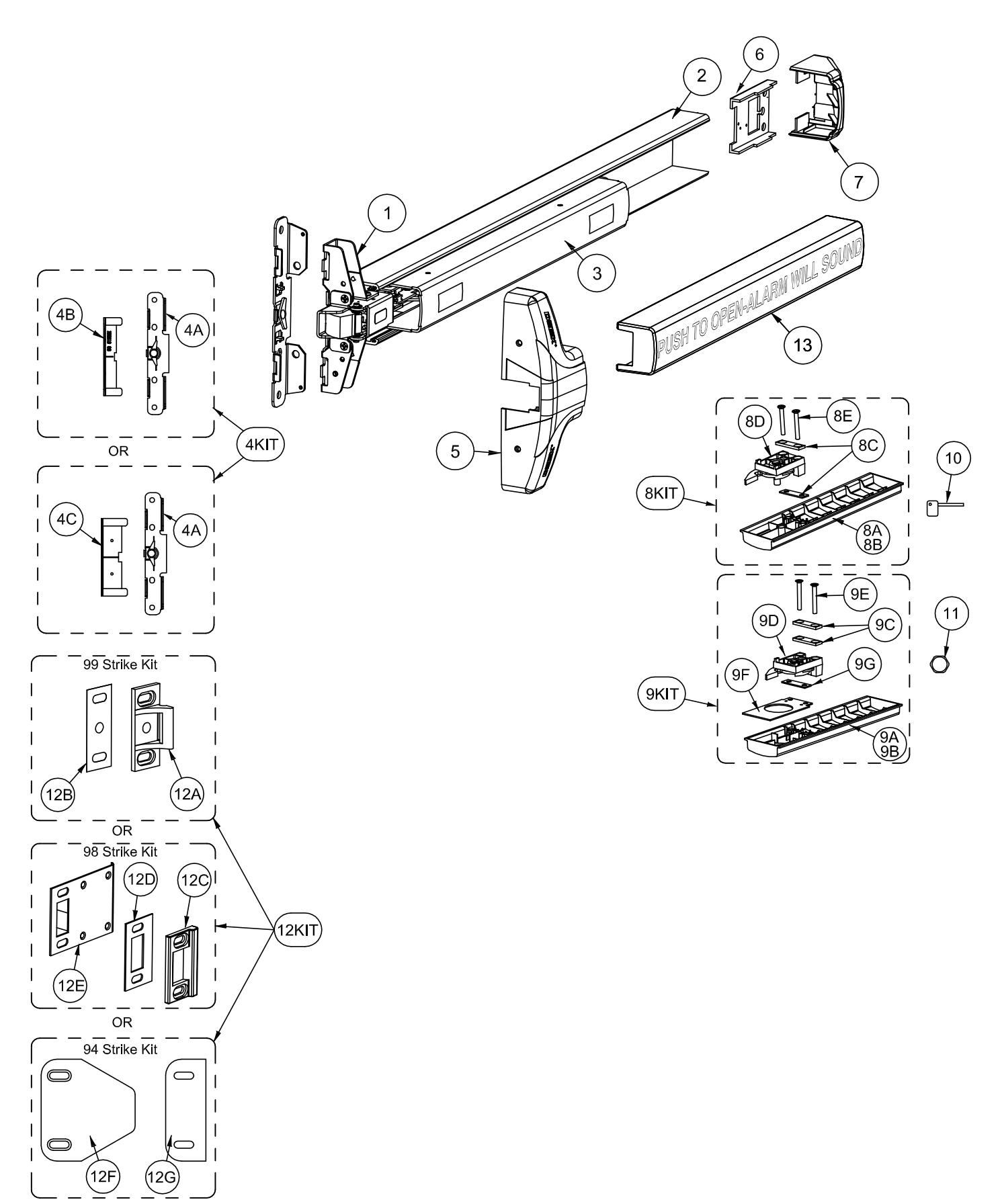
| Device parts breakdown view | 2 |
| Device parts breakdown list with part numbers | 3 |
| Hardware List with part numbers & tools required | 4 |
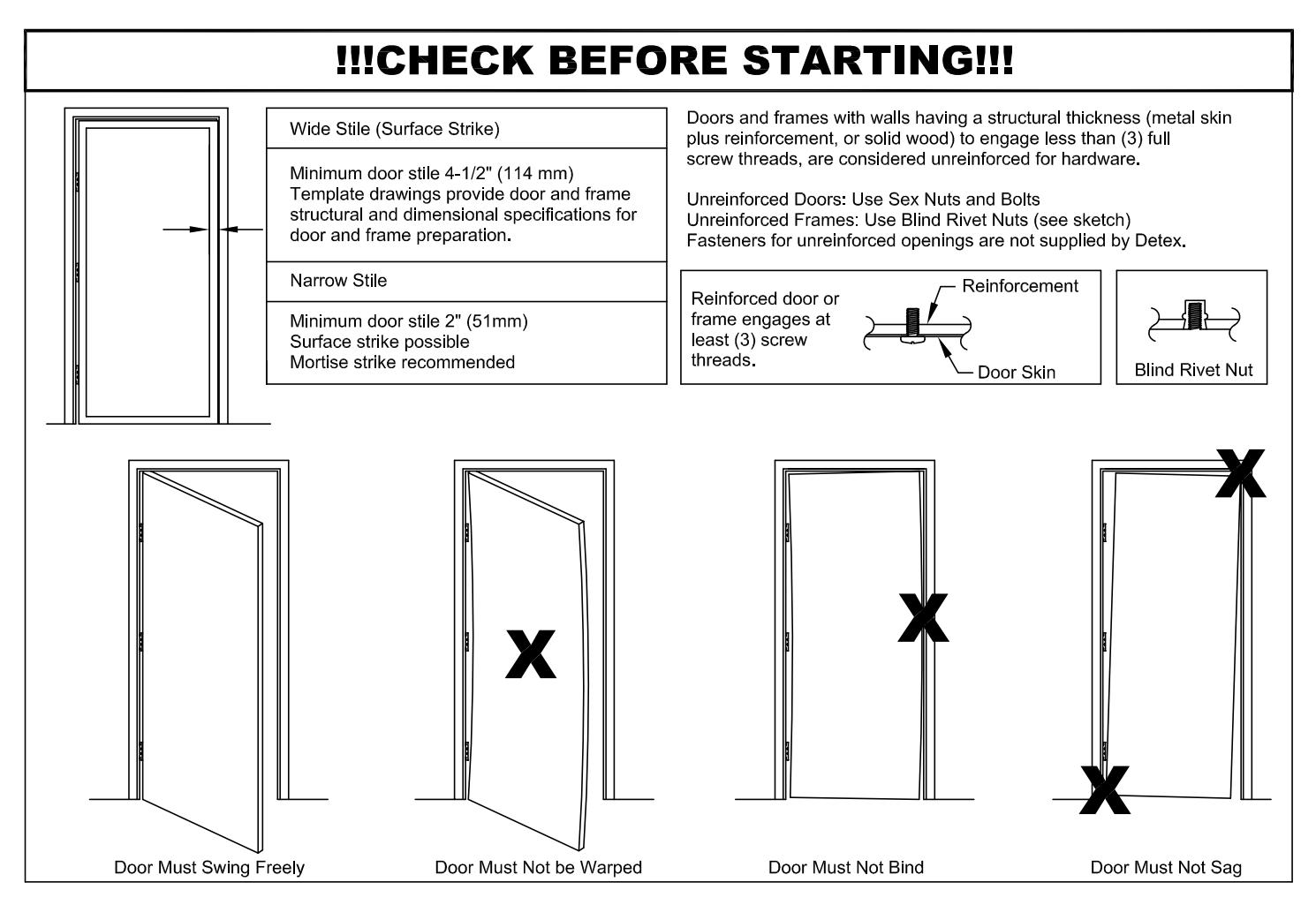
| Door condition check | 5 |
| Mounting plate and 99 Strike installation | 6 |
| Device installation | 7 |
| Check for device clearance, Mortise cylinder installation | 8 |
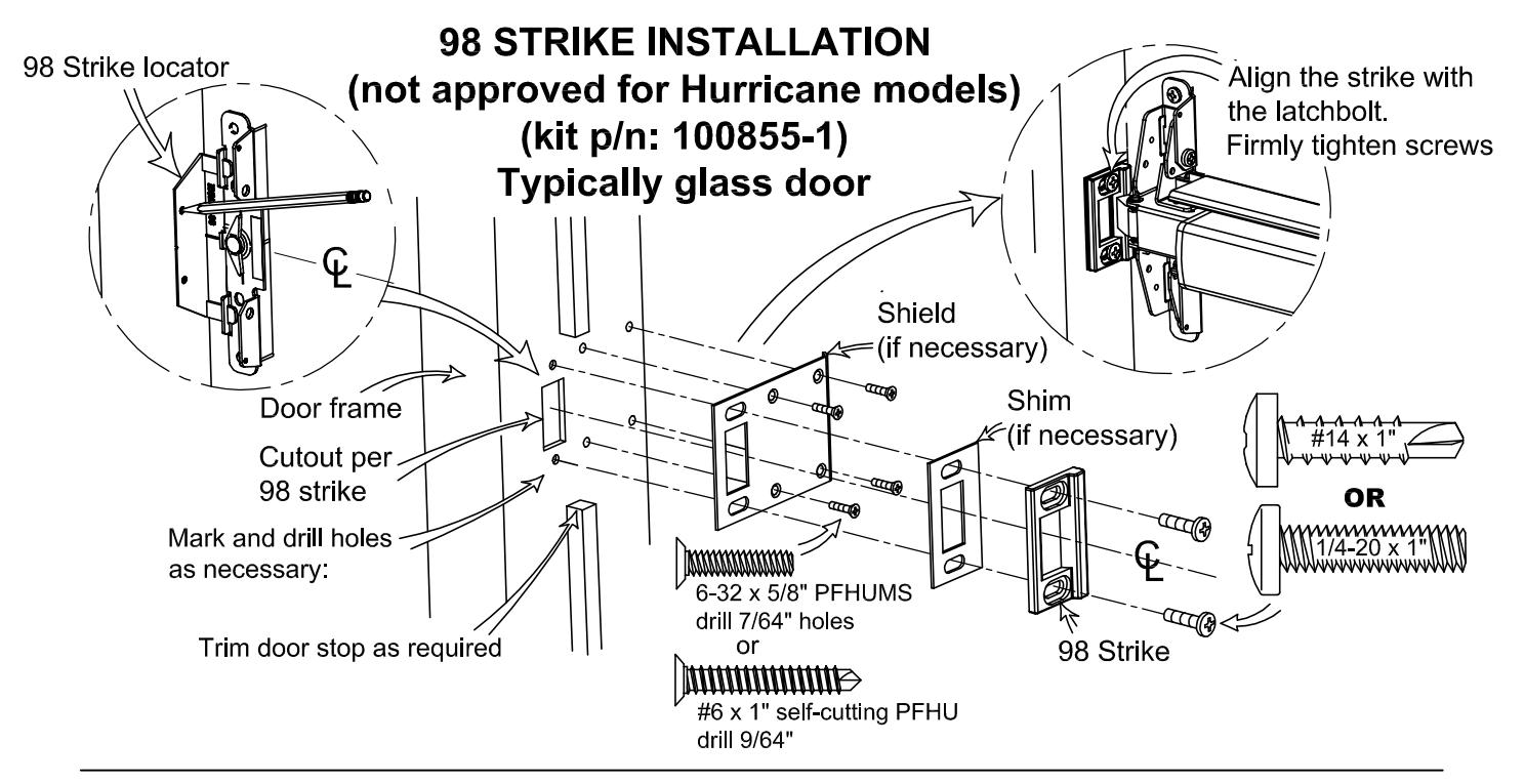
| 98 Strike installation, Strike hook installation | 9 |
| 94 Double Door Strike installation (if required) | 10 |
| Optional Accessories | 11 |
Should you have a Question/Problem with your Detex device please call Detex Technical Support from the job site at 1-800-729-3839 and choose option 2 on our menu. Please do not return the product to the distributor.
For WARRANTY information, scan code below or go to www.detex.com/warranty


For device installation videos, scan code below or go to www.detex.com/videos
101275 Page 2
| PARTS BREAKDOWN | ||||
|---|---|---|---|---|
| Item | Order | Description | ||
| 1 | Part # | Centercase Assembly, Narrow Stile, V40 series | ||
|
100698-5
106281 |
Baseplate Extrusion, 36", Silver | |||
| 2 | 106285 | Baseplate Extrusion, 48", Silver | ||
| 106289 | Baseplate Extrusion, 36", Black | |||
| | | | 106269 | Baseplate Extrusion, 48", Black | ||
| 100290 | Pushpad Subassembly, 36" | |||
| 3 | 103065-1 | Pushpad Subassembly, 48" | ||
| Mounting Plate/Strike Locator Kit, Narrow Stile, 98 Strike BP2 (includes 4A & 4B) | ||||
| 4KIT | 103806-1 | Mounting Plate/Strike Locator Kit, Narrow Stile, 99 Strike BP2 (includes 4A & 4C) | ||
| 40 | 103806-3 | |||
| 4A | 100696-1 | Mounting Plate, BP2, Narrow Stile | ||
| 4B | 101899 | Strike Locator 2" Glass Door (98) | ||
| 4C | 100212 | Strike Locator, Standard (99) | ||
| 5 | 101805-1 | Centercase Cover, V40 series | ||
| 6 | 101844-1 | Endcap bracket w/o battery holder | ||
| 101844 | Endcap bracket w/ battery holder | |||
| 7 | 101822 | Endcap | ||
| 8KIT | 101803-1 | Fillerplate, Subassembly, S&R, Hex Dogging, HD, V40 series, 36" (includes 8A or 8B through 8E) | ||
| 8A | 101812-1 | Fillerplate, HD, 36" | ||
| 8B | 101812-2 | Fillerplate, HD, 48" | ||
| 8C | 100164 | Spacer, dogging bracket, .120" thick | ||
| 8D | 102216-4 | Die cast dogging assembly, HD | ||
| 8E | PP-5802-124 | Screw, mach, 10-32 x 1-1/2" PFH | ||
| 9KIT | 102195-1 | Fillerplate, Subassembly, S&R, Cylinder Dogging, CD, V40 series, 36" (includes 9A or 9B through 9G) | ||
| 9A | 102194-1 | Fillerplate, CD, 36" | ||
| 9B | 102194-2 | Fillerplate, CD, 48" | ||
| 9C | 100164 | Spacer, dogging bracket | ||
| 9D | 102216-3 | Die cast dogging assembly, CD | ||
| 9E | PP-5802-124 | Screw, mach, 10-32 x 1-1/2" PFH | ||
| 9F | 102196 | Bracket, fillerplate, V40, CD | ||
| 9G | 100938 | Spacer, dogging bracket, .060" thick | ||
| 10 | 100450 | Hex Key (for Hex Dogging) | ||
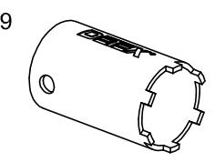
| 11 | 100783 | Cylinder Nut (for Cylinder Dogging) | ||
| | | | 100855-2 | 99 Strike Kit (includes 12A & 12B) | ||
| 12KIT | 100855-1 | 98 Strike Kit (includes 12C, 12D & 12E) | ||
| 102212-1 | 94 Double Door Strike Kit (includes 12F & 12G) | |||
| 12A | 100234-1 | Strike, Non-roller | ||
| 12B | 100088 | Strike Shim | ||
| 12C | 100480 | Strike, Mortise | ||
| 12D | 100482 | Shim, Mortise Strike | ||
| 12E | 100481 | Shield, Strike | ||
| 12F | 102211 | Double Door Strike Plate | ||
| 12G | 102214 | Shim, 94 strike | ||
| 105417-1 | Pushpad Wrap, 36", Red (English text) | |||
| 13 | 105417-2 | Pushpad Wrap, 48", Red (English text) | ||
| | . | | 105417-3 | Pushpad Wrap, 36", Black | ||
| 105417-4 | Pushpad Wrap, 48", Black | |||
Your particular part or configuration may not be shown: Contact Detex technical support at 800-729-3839 (option 2)
Hardware Table for BASIC device mounting. Additional hardware is provided per the device configuration in kit form and is addressed on the appropriate pages as required
Device hardware kit: p/n 101809-2 for Hex Dogging (HD) Device hardware kit: p/n 101809-5 for Cylinder Dogging (CD)
| Fastener Part No | Drill Bit constant | |
|---|---|---|
|
P/N: 100980
1/4-20 x 1" PPH |
#7 or 13/64" | |
|
P/N: 101621-5
1/4-20 x 1/4" PPHMS |
#7 or 13/64" | |
| Jumuu |
P/N: 100162-106
6-32 x 3/8" PFHUMS |
|
|
P/N: 103276-65
#14 x 1-1/2" PPH self-drilling |
1/8 pilot hole recommended for self-drilling screws | |
|
P/N: PP-5183-110
#14 x 1-1/4" PPH wood screw |
1/8 pilot hole recommended for wood screws | |
|
P/N: PP-5067-25
#14 Lockwasher |
| 99 Strike Kit: p/n 100855-2 or 98 Strike Kit: p/n 100855-1 | ||||
|---|---|---|---|---|
|
P/N: 100980
1/4-20 x 1" PPH |
#7 or 13/64" | in both kits | ||
|
P/N: 100112
10-24 x 5/8" PFHUMS |
in 99 kit only | |||
|
P/N: 100162-1
6-32 x 5/8" PFHUMS |
in 98 kit only | |||
|
P/N: 103276-63
#14 x 1" PPH |
1/8 pilot hole recommended for self-drilling screws | in both kits | ||
|
P/N: 103277-216
#10 x 1" self-cutting PFHU |
in 99 kit only | |||
|
P/N: 101451-1
#6 x 1" self-cutting PFHU |
in 98 kit only | |||
Tools Required:
Safety Glasses Pencil Phillips & small flat Screw Drivers Power Drill Hammer Combination Square
Tape Measure Pliers Center Punch
Level 1/4-20 Tap Saw for cutting device if necessary (chopsaw preferred)
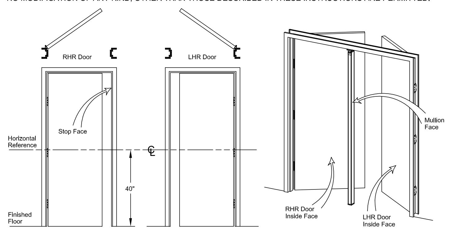
NOTE: 750mm MAXIMUM DOOR WIDTH OPENING FOR EUROPE FOR 36" DEVICE (1000mm MAXIMUM DOOR WIDTH OPENING FOR EUROPE FOR 48" DEVICE) THE SAFETY FEATURES OF THIS PRODUCT ARE ESSENTIAL TO ITS COMPLIANCE WITH EN 1125. NO MODIFICATION OF ANY KIND, OTHER THAN THOSE DESCRIBED IN THESE INSTRUCTIONS ARE PERMITTED.
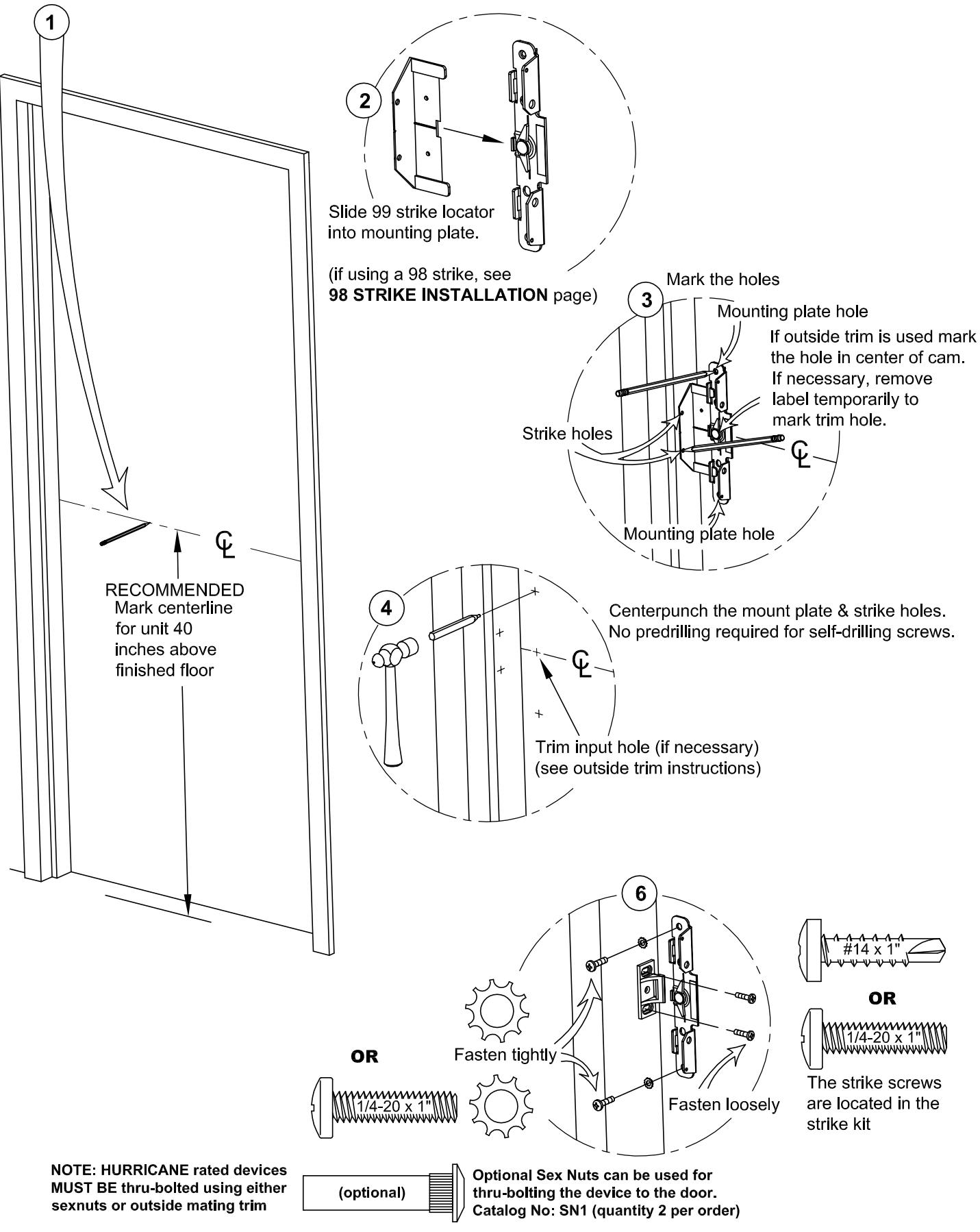
MOUNTING PLATE & STRIKE INSTALLATION:
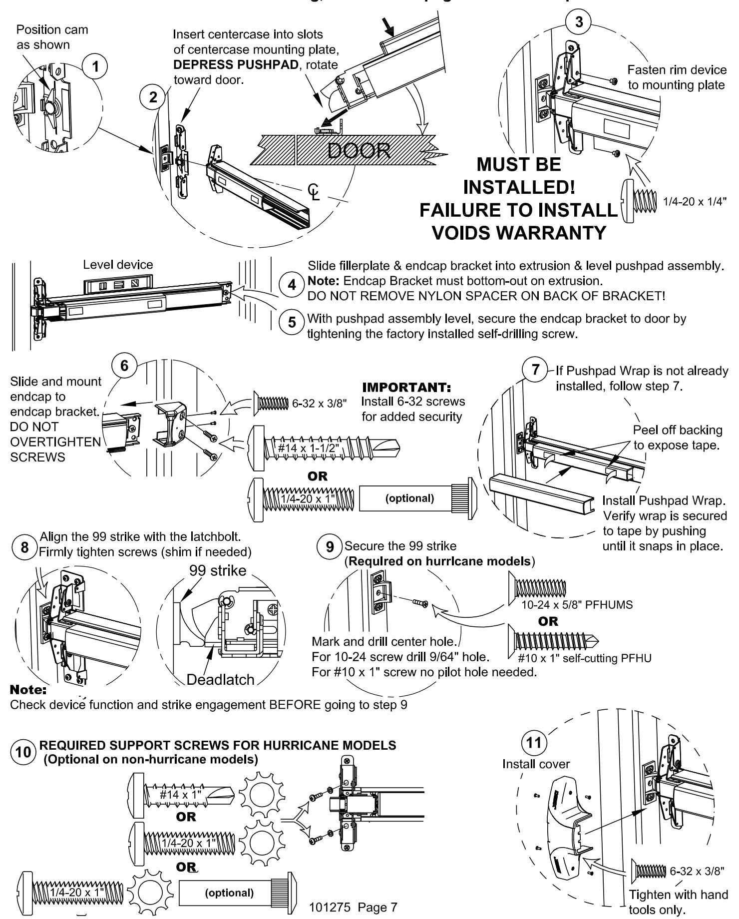
DEVICE INSTALLATION: NOTE: If device is too long, refer to next page for cut-down procedure.
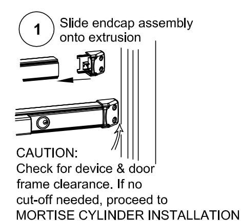
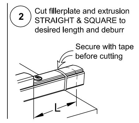
CHECKING FOR DEVICE CLEARANCE (Cut-Off procedure if required)
| Non-Electrified | |||
|---|---|---|---|
| Minimum Fillerplate | |||
| Length | |||
| Type | Length (L) | ||
| LD | 2-1/2" | ||
| HD/CD | 3" | ||
For further Cut-Down information, see: www.detex.com/cutdown
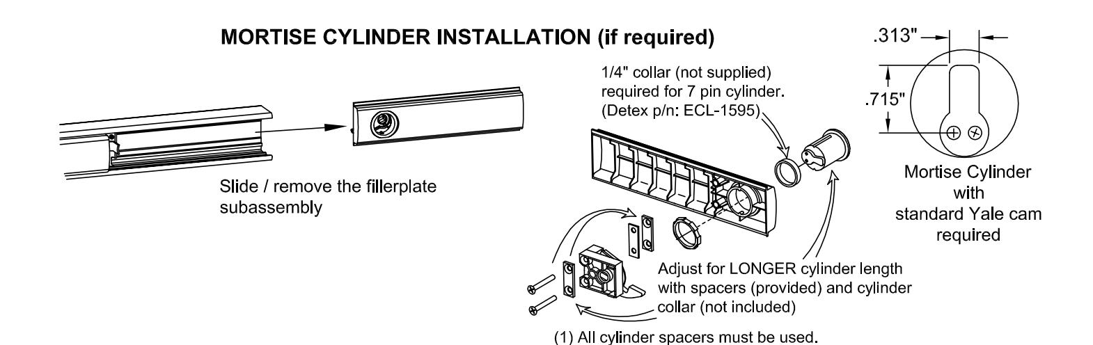
(2) Turn key max CCW before installing slide in fillerplate.
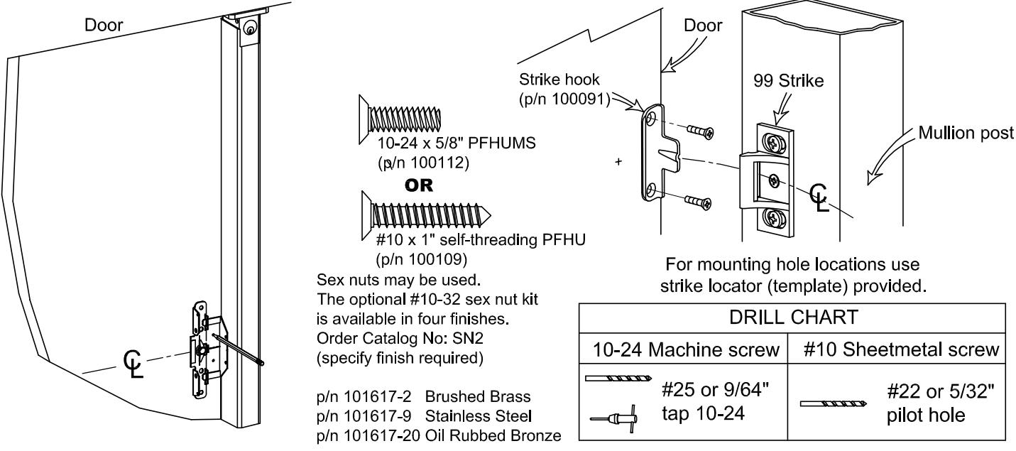
STRIKE HOOK INSTALLATION
Strike Hook Kit p/n 101795
(Caution: This installation is required on fire rated door openings with removable mullion.)
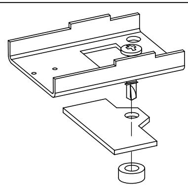
Narrow Stile Endcap Mounting Plate Fascia (p/n 101864) (For use on Glass Doors)
- a. Remove the endcap mounting bracket.
- b. Remove nylon spacer.
- c. Slide facsia onto screw.
- d. Reinstall nylon spacer.
- e. Reinstall endcap mounting bracket.
94 DOUBLE DOOR STRIKE INSTALLATION (not approved for Hurricane models) (if required)
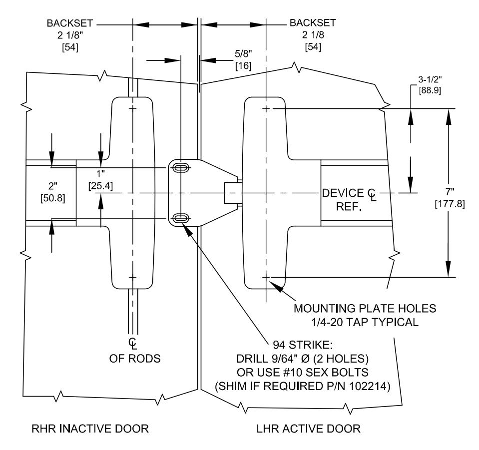
NOTE: FOR DEVICE FUNCTION AND OTHER DIMENSIONS, SEE APPROPRIATE DEVICE AND/OR TRIM INSTRUCTIONS
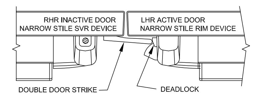
THE DEVICE USED ON THE ACTIVE DOOR SHOULD BE INSTALLED SO THAT THE STRIKE WILL DEPRESS THE DEADLOCK SUFFICIENTLY TO ALLOW FOR ANY AND ALL ALARM / ELECTRONIC FUNCTIONS. ADD SHIM (P/N 102214) AS REQUIRED. TWO PROVIDED IN KIT. THE INACTIVE DOOR SHOULD CLOSE FIRST.
Optional Accessories
Glass Bead Kit
Catalog No: GB2 - Glass Bead Kit, 40 series p/n. 101644



The #1/4-20 kit is available in (4) finishes:
Catalog No: SN1 Brushed Brass BHMA 606 Finish Catalog No: SN1 Oil Rubbed Bronze BHMA 613 Finish Catalog No: SN1 Brushed Chrome BHMA 626 Finish Catalog No: SN1 Stainless Steel BHMA 630 Finish
p/n: 101616-X
Tamper Kit
(Security Kit) Catalog No: SSK3 p/n: 101233
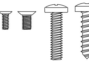
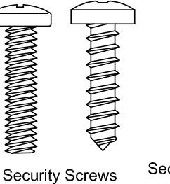
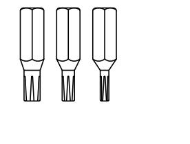
Security Pin TORX® Bits provided
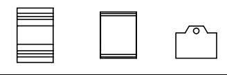
Narrow Stile Door Kit
(Splice Kit may be used with either 3-0 or 4-0 units) Catalog No: NSK1
p/n: 101879-1 (628 Finish, Clear) p/n: 101189-2 (711 Finish, Black)
(includes 98 Strike)
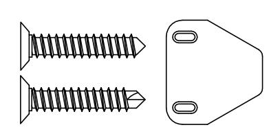
Double Door Strike Kit
Catalog No: 94 (with Security screws) p/n: 102212-1
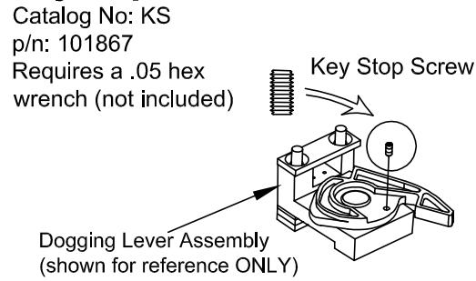
Key Stop Kit
Cylinder nut socket kit p/n: 103779
The following Models in the series were evaluated by UL: Controlled Exit Panic Devices; Model 10 and 40. These devices may be suffixed with 01, 02, 03, 08, 09, or 14 followed by C, CN, D, DN, DT, DNT, DU, DNU, P, PN, W or WS, followed by BP1, BP2, BP3, BP5, BP6, BP7or BP8 followed by 605, 606, 611, 612, 613, 625, 626, 628, 629, 630, 693, 695 or 711 followed by the RHR or LHR, followed by EA, which may be followed by LD or CD, followed by 605, 606, 611, 612, 613, 625, 626, 628, 629, 630, 693, 695 or 711 followed by 98 or 99, followed by 36 or 48.