Detex Advantex 60-61-Installation Instructions
Open the original PDF document
View PDFC


Detex Corporation, 302 Detex Drive, New Braunfels, Texas 78130-3045 830-629-2900 / 800-729-3839 / Fax 800-653-3839 / Text photos only: 830-481-6433 / INTERNET: www.detex.com
INSTALLATION INSTRUCTIONS FOR CONCEALED VERTICAL ROD
Concealed Vertical Rod Exit Device 60 / F60 / 61 / F61 Series for Narrow to Wide Stile Aluminum or FRP door applications
R
Drawing No. 105260
| Table of Contents | Page |
|---|---|
| Device parts breakdown view | 2 |
| Device parts breakdown list with part numbers | 3 |
| Hardware List with part numbers & tools required | 4 |
| Step 1: Door/opening measurements | 5 |
| Step 2: Door & frame prep | 6 |
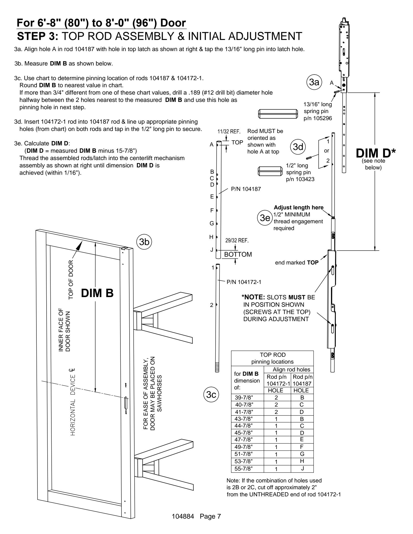
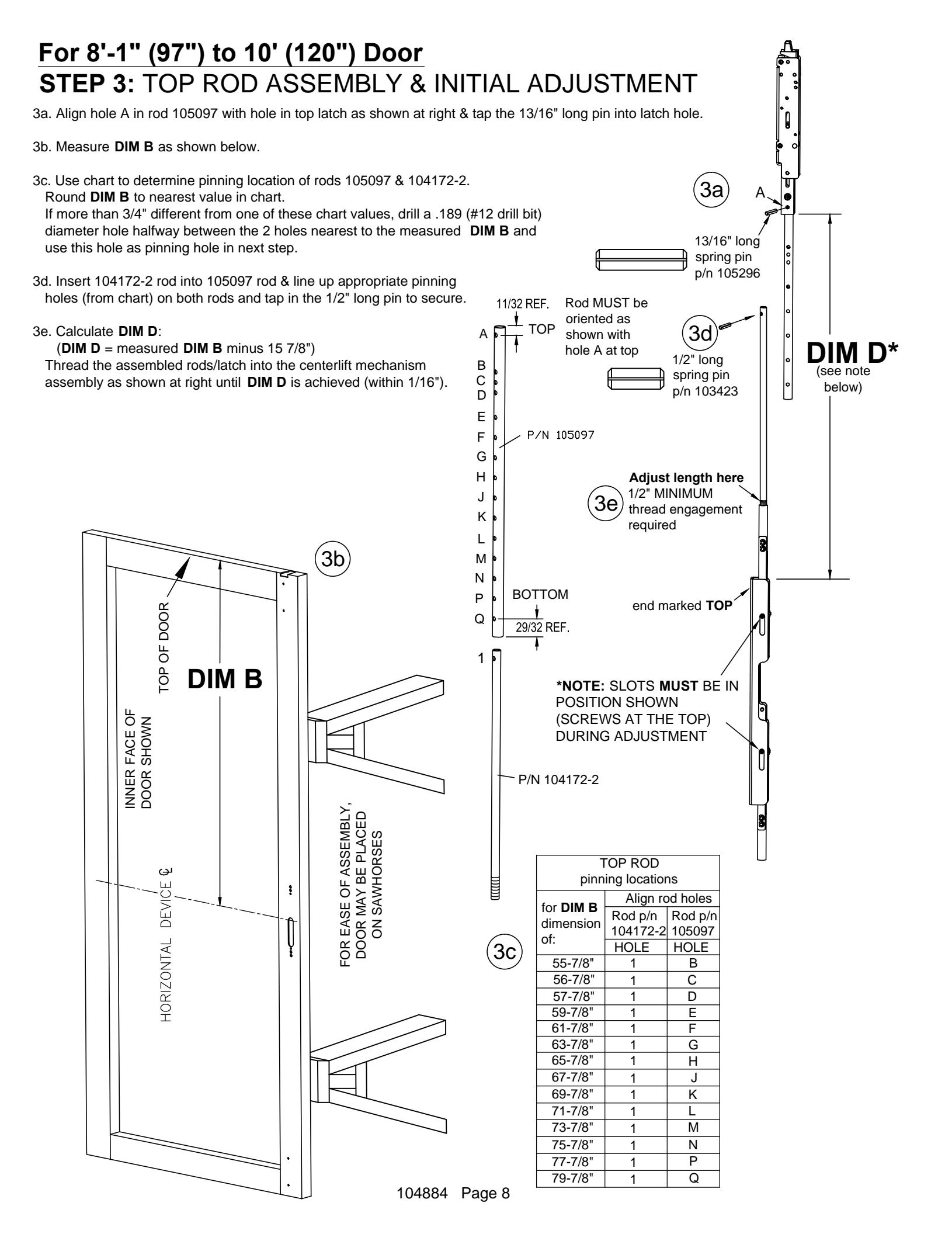
| Step 3: Top rod assembly and initial adjustment | 7 & 8 |
| Step 4: Bottom rod / latch assembly initial adjustment | 9 |
| Step 5: Visual alignment check | 10 |
| Step 6: Install top latch mounting bracket | 11 |
| Step 7: Insert rod / latch / centerlift assembly into door | 11 |
| Step 8: Secure rod / latch / centerlift assembly to door | 12 |
| Step 9: Verify centerlift mechanism operation | 12 |
| Step 10: Hang door / assemble device to door | 13 |
| Check device for clearance | 14 |
| Install mortise cylinder | 14 |
| Step 11: Install top strike | 15 |
| Step 12: Install bottom strike | 15 |
| Step 13: Fine latch adjustment | 16 |
| Step 14: Install covers | 17 |
| Step 15: Install auxiliary bolt | 17 |
| Optional accessories | 18 |
For WARRANTY information, scan code below or go to www.detex.com/warranty
For device installation videos, scan code below or Owner's Copy go to www.detex.com/videos

Should you have a Question/Problem with your Detex device please call Detex Technical Support from the job site at 1-800-729-3839 and choose option 2 on our menu. Please do not return the product to the distributor.

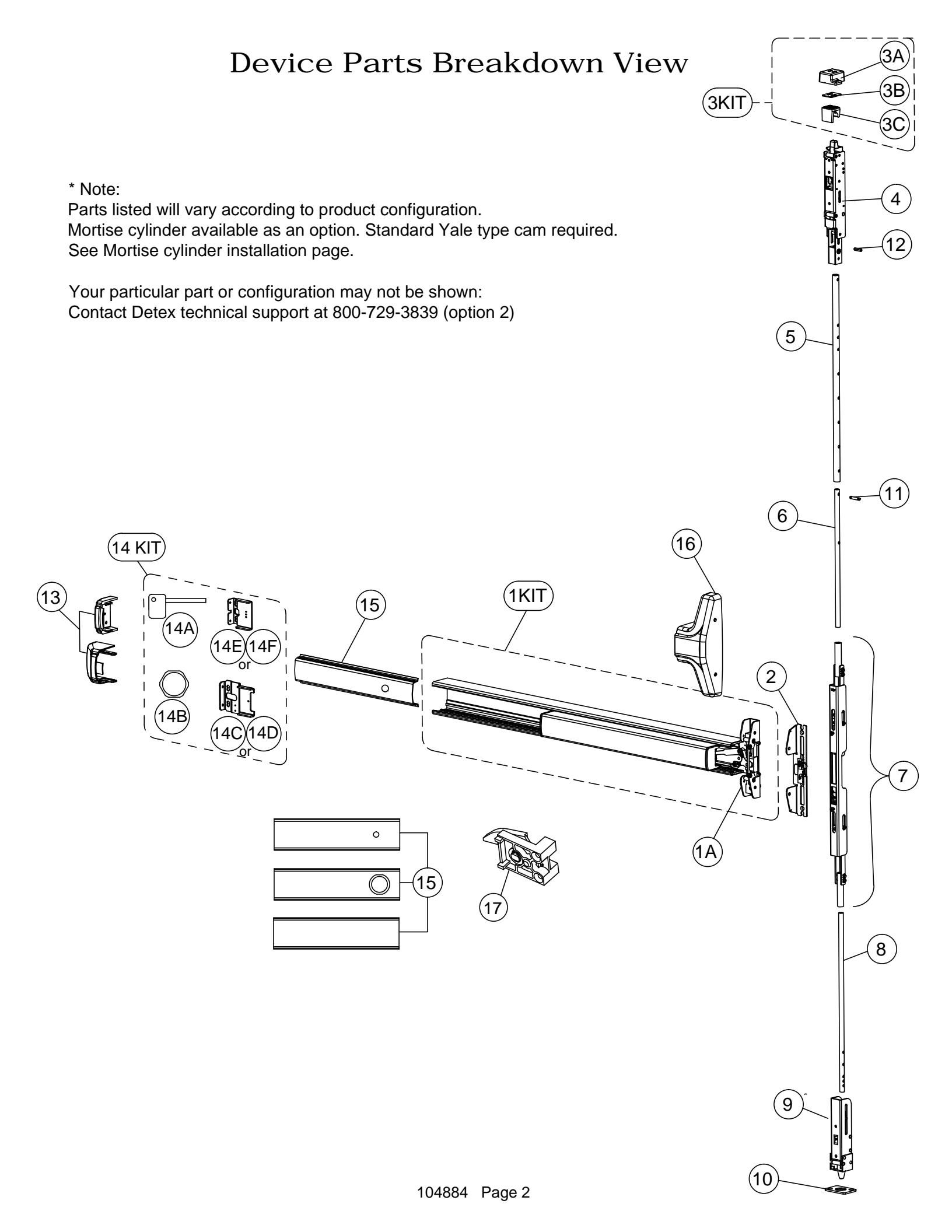
| Dev | rice Parts Breakdown Part Numbers | ||
|---|---|---|---|
| ITEM | PART # | DESCRIPTION | |
| ALCIT | 105500-148 | S&R CVR Centercase/Pushpad Assy, 60 RHR | |
| 1KII | | S&R CVR Centercase/Pushpad Assy, 60 LHR | ||
| 104111-1 | Centercase, CVR, Narrow, RHR | ||
| Centercase, CVR, Narrow, LHR | |||
| 104148-1 Mounting plate, Narrow, CVR, BP10 | Mounting plate, Narrow, CVR, BP10 | ||
| 2 | 2 104148-2 Mounting plate, Narrow, CVR, BP12 | ||
| 3KIT | 105257-2 | Top strike kit | |
| 3B | 105246 | CVR strike shim | |
| 3A | 105235-1 | CVR top strike pocket | |
| 3C | 105236-1 | CVR top strike insert | |
| 4 | 104121-1 | Top latch (Panic) | |
| 4 | 104121-2 | Top latch (Fire) | |
| 5 | 104187 | Outer top rod, 7' thru 8' | |
| 3 | 105097 | Outer top rod, 8'-1" thru 10' | |
| 6 | 104172-1 | Inner top rod, 7' thru 8' | |
| 6 | 104172-2 | Inner top rod, 8'-1" thru 10' | |
| 7 | 105990-1 | Center lift mechanism assembly, Top & Bottom | |
| ′ [ | 105990-2 | Center lift mechanism assembly, Top Rod Only | |
| 8 | 105098 | CVR bottom rod | |
| 9 | 104190-1 | Bottom latch, Aluminum door application | |
| 10 | 105257-3 | Bottom strike kit | |
| 11 | 103423 | Spring pin 3/16 x 1/2 | |
| 12 | 105296 | Spring pin 3/16 x 13/16 | |
| 13 | 101642-9 | Endcap, EC1 (ramped) Stainless Steel 630 | |
| 13 | 104304-9 | Endcap, EC2 (flush) Stainless Steel 630 | |
| 106431-1 | Device Hardware Kit, HD, EC1 (not all components shown, includes Items 14A & 14C) | ||
| 106431-2 | Device Hardware Kit, CD, EC1 (not all components shown, includes Items 14B & 14C) | ||
| 14KIT | 106431-3 | Device Hardware Kit, EA, EC1 (not all components shown, includes Items 14B & 14D) | |
| 106431-21 | Device Hardware Kit, HD, EC2 (not all components shown, includes Items 14A & 14E) | ||
| 106431-22 | Device Hardware Kit, CD, EC2 (not all components shown, includes Items 14B & 14E) | ||
| 106431-23 | Device Hardware Kit, EA, EC2 (not all components shown, includes Items 14B & 14F) | ||
| 14A | 100450 | Hex Key (for Hex Dogging) | |
| 14B | 100783 | Cylinder Nut (for Cylinder Dogging) | |
| 14C | 100147 | Endcap bracket for EC1 (ramped) endcap w/o battery holder | |
| 14D | 101093 | Endcap bracket for EC1 (ramped) endcap w/ battery holder | |
| 14E | 104303 | Endcap bracket for EC2 (flush) endcap w/o battery holder | |
| 14F | 104636 | Endcap bracket for EC2 (flush) endcap w/ battery holder | |
| 100860-165 | Fillerplate Subassembly, S&R, Hex Dogging, HD, 630 | ||
| 15 | 100860-166 | Fillerplate Subassembly, S&R, Hex Dogging, CD, 630 | |
| 100860-167 | Fillerplate Subassembly, S&R, Hex Dogging, LD, 630 | ||
| 16 | 104112-9 | Centercase Cover, Stainless Steel, Narrow 630/628 | |
| 17 Hex Dogging Assembly | |||
| 102216 | Cylinder Dogging Assembly | ||
Your particular part or configuration may not be shown: Contact Detex technical support at 800-729-3839 (option 2)
Hardware Table for BASIC device mounting. Additional hardware is provided per the device configuration in kit form and is addressed on the appropriate pages as required.
| Device Mounting Hardware | |||
|---|---|---|---|
|
#14 x 1" PPHS
P/N: PP-5183-108 |
Used to install backplate & endcap bracket to hollow metal/aluminum doors. Drill Bit - 3/16 pilot hole | ||
|
#14 x 1/2" PPHS
P/N: PP-5183-104 |
Used to install backplate & endcap bracket to wood doors. | ||
|
1/4-20 x 1" PPH
P/N: 100980 |
Used with sex bolts or lever trim (1-3/4 door). Drill Bit - #7 or 13/64" | ||
|
1/4-20 x 1-1/2" PPH
P/N: 100954 |
ALTERNATE SCREW Used with sex bolts or lever trim (2" plus door) Drill Bit - #7 or 13/64" | ||
|
10-24 x 1/4" PPH
P/N: PP-5304-104 |
Used to install device centercase to backplate | ||
|
10-24 x 5/8" PFHU
P/N: 100112 |
Used to install centerlift mechansim to backplate | ||
|
10-32 x 5/16" PFHU
P/N: 101632-2 |
Used to install endcap to endcap bracket. (Multiple finishes included) | ||
| Dumm |
6-32 x 3/8" PFHU
P/N: 100162-106 |
Used to install centercase cover to backplate (Multiple finishes included) | |
|
1/4 Lockwasher
P/N: PP-5067-25 |
Lockwashers | ||
Sex nuts, if ordered. Sex nuts are used with screws in device hardware kit.
|
1/4-20 x 1.60 Sex nut
P/Ns: 105274-9 (Stainless Steel) 105274-2 (Brushed Brass) 105274-25 (Oil Rub Bronze) |
Used to install backplate and endcap bracket to door If using sex nuts with TRIM: Drill 9/32 hole through interior door face. Drill 1/2 hole through exterior door face. If using sex nuts without TRIM: Drill 3/8 hole through exterior door face. | ||
|---|---|---|---|
| Strike Mounting Hardware | |||
|
#10 x 1" PFHU
P/N: 100109 |
Used to install bottom strike to floor. (Used with anchors, two styles of anchors included) | ||
|
10-24 x 1/2" PFHU
P/N: 100112-108 |
Used to install bottom strike to floor (alternate) | ||
|
10-32 x 1/2" PFH
P/N: PP-5802-308 |
Used to install top strike pocket to header and strike insert to top strike pocket | ||
| Latch Mountir | ng Hardware | ||
|
10-24 x 5/16" PFH
P/N: 100112-105 |
Used to install bracket to bottom assembly and top latch | ||
| { mmm |
10-24 x 3/8" PPH
P/N: PP-5304-306 |
Hollow Metal / Wood doors: bottom bracket to latch Hollow Metal doors: Top & bottom latch brackets to door | |
|
#10 x 3/4" PPHS
P/N: PP-5183-66 |
Used to install bottom assembly to bottom of door & top latch to top of door (For NON-FIRE RATED) | ||
Power Drill Level Screw Drivers
Hammer Pencil Center Punch
Tools Required
Drill Bit Set Safety Glasses Pliers 104884 Page 4 Tape Measure
Hack Saw (Chopsaw preferred) Tap Wrench/ Hex Wrench - 5/64 Masonary Bits - 3/16", 5/16" & 1"
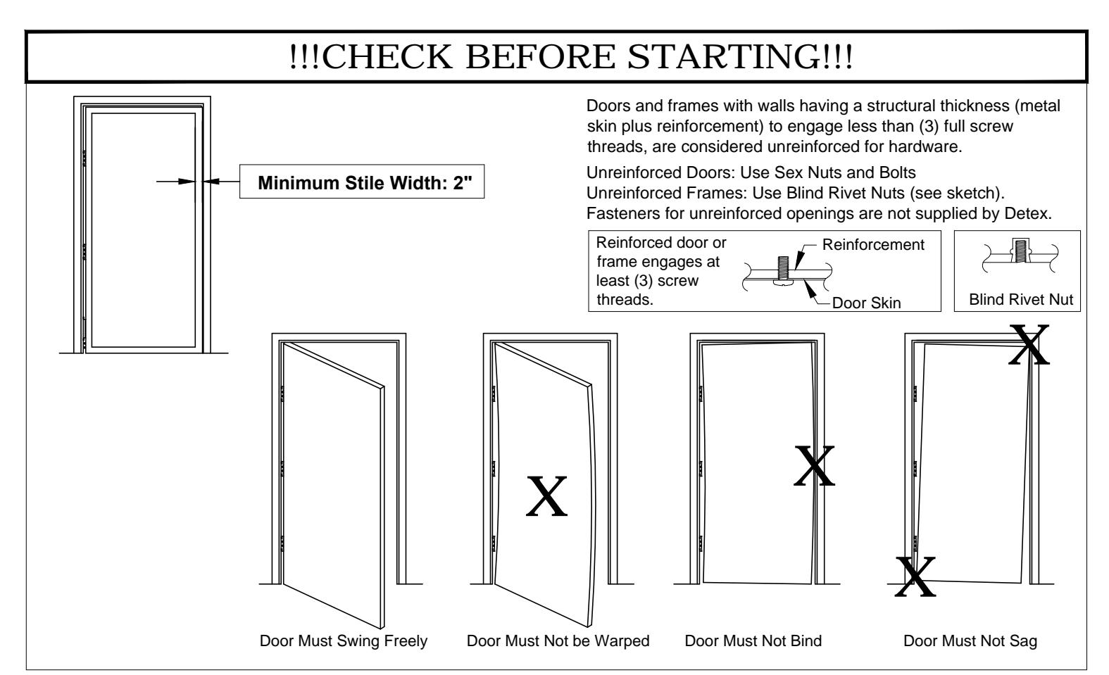
NOTE : LOCAL CODES MAY REQUIRE THROUGH BOLTING. SEX NUTS ARE NOT INCLUDED WITH THIS DEVICE. SEX NUTS CAN BE PURCHASED SEPARATELY.
STEP 1: DOOR / OPENING MEASUREMENTS
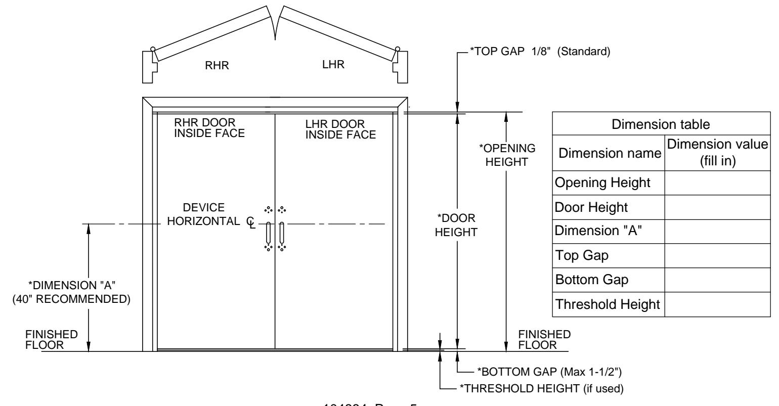
Measure per figure below:
*These dimensions will be needed during rod length adjustment. Measure door before removing.
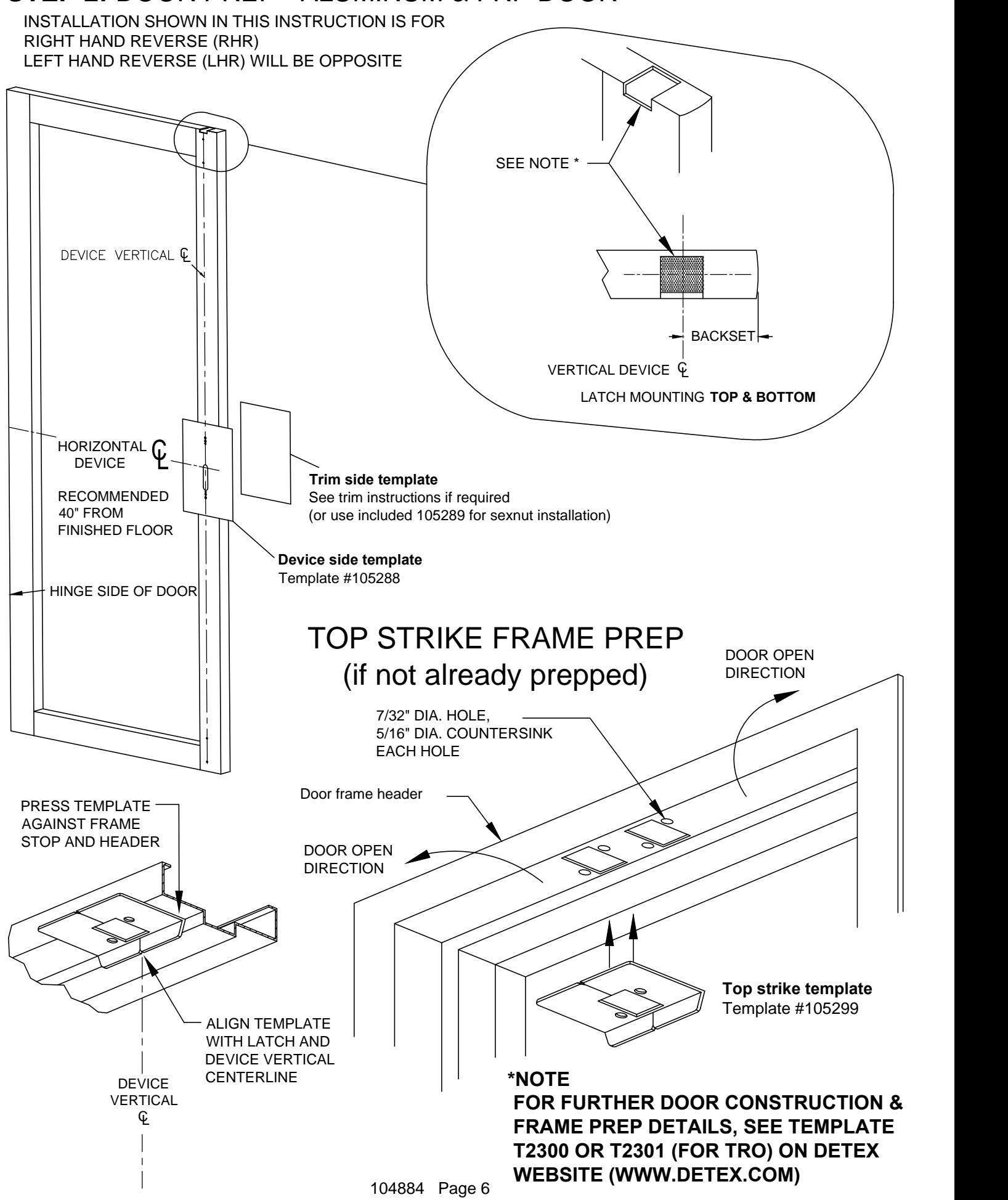
STEP 2: DOOR PREP - ALUMINUM & FRP DOOR
STEP 4:
BOTTOM ROD / LATCH ASSEMBLY & ADJUSTMENT
(Disregard if TRO device is being installed)
4a. Using DIM A as measured in step 1, use chart to determine pinning location.
If DIM A is less than 37-1/4" from finished floor, a new pin hole must be drilled through 105098 rod. Subtract the centerline dimension from 38" and measure up this distance from hole V. Mark and drill .189 diameter hole (#12 drill).
| Align rod holes with bottom latch (round DIM A to nearest value shown) | ||
|---|---|---|
| DIM A Bottom Rod | ||
| (device € at | p/n: 105098 | |
| distance from floor) | use HOLE | |
| 38" | V | |
| 39" | W | |
| 40" | Χ | |
| 40-3/8" | Υ | |
| 40-3/4" | Z | |
ROD P/N 105098
Note: If hole V or W is used (or if new hole is drilled closer to threaded end), trim off UNTHREADED end of rod as needed to allow rod to slide into bottom bolt far enough to pin.
- 4b. Remove clip 103551 and slide pin out. Place bottom rod 105098 into bolt, line up holes and replace pin and place clips into pin grooves.
- 4c. DIM C is the target length.
FINISHED FLOOR
For no threshold or threshold 1/2" or less:
DIM C = measured DIM A minus 8". NOTE: SLOTS MUST BE IN For threshold greater than 1/2": POSITION SHOWN DIM C = measured DIM A minus 8" minus threshold height (SCREWS AT THE TOP) DURING ADJUSTMENT The bottom bolt vertical travel from fully extended to fully retracted is approximately 9/16. 4d. Thread bottom rod into centerlift mechansim to achieve DIM C (within 1/16"). Adjust length here ŧ 1/2" MINIMUM HORIZONTAL DEVICE thread engagement required DIM C INNER FACE OF DOOR SHOWN BOTTOM ROD 4c p/n 105098 DIM A CLIP p/n 10355 BOTTOM OF DOOR p/n 105248 BRACKET
104884 Page 9
BOLT _____ p/n 103536
STEP 5:
VISUAL ALIGNMENT CHECK:
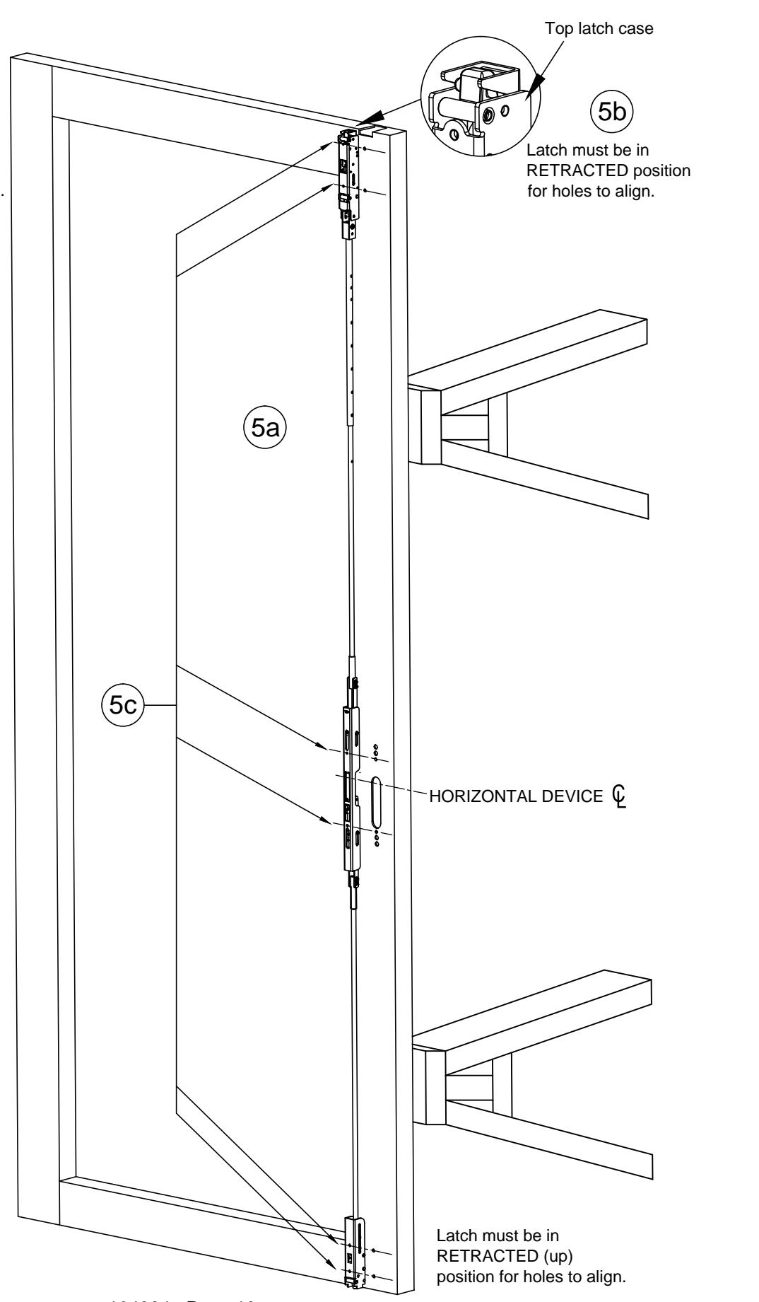
- 5a. Lay internal latch components onto door for trial fit. Take care to protect door finish.
- 5b. Ensure top latch is in retracted position. Hold top rod in place and push top latch case towards device until latchbolt is fully retracted. CL
- 5c. Mounting holes for top latch, centerlift and bottom latch should line up with mounting holes in door. If not, go back to steps 3 & 4 and verify rod length dimensions.
STEP 6:
ATTACH TOP LATCH MOUNTING BRACKETS
No brackets necessary for aluminum door applications - continue to step 7
STEP 7:
INSERT ROD / LATCH / CENTERLIFT ASSEMBLY INTO DOOR
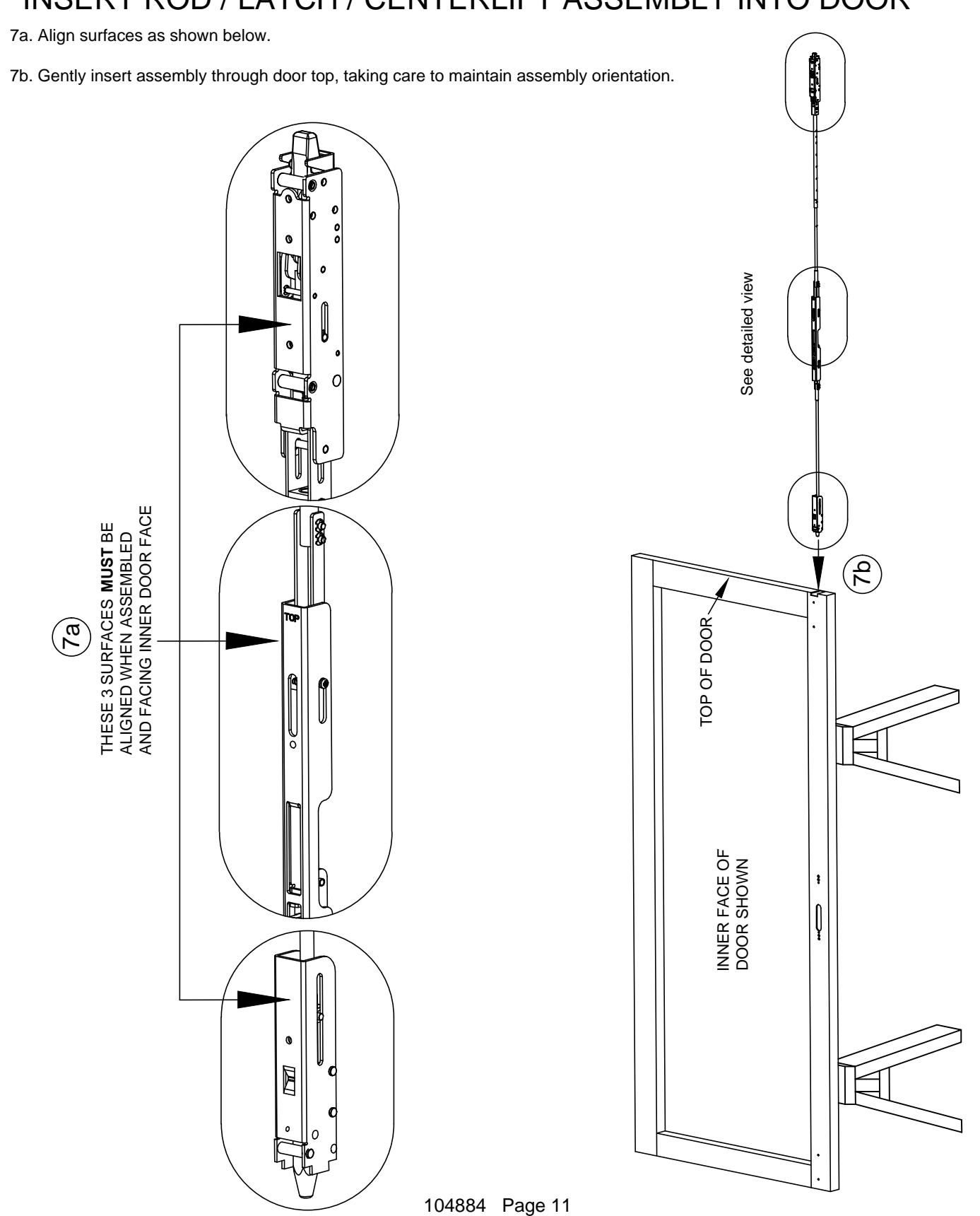
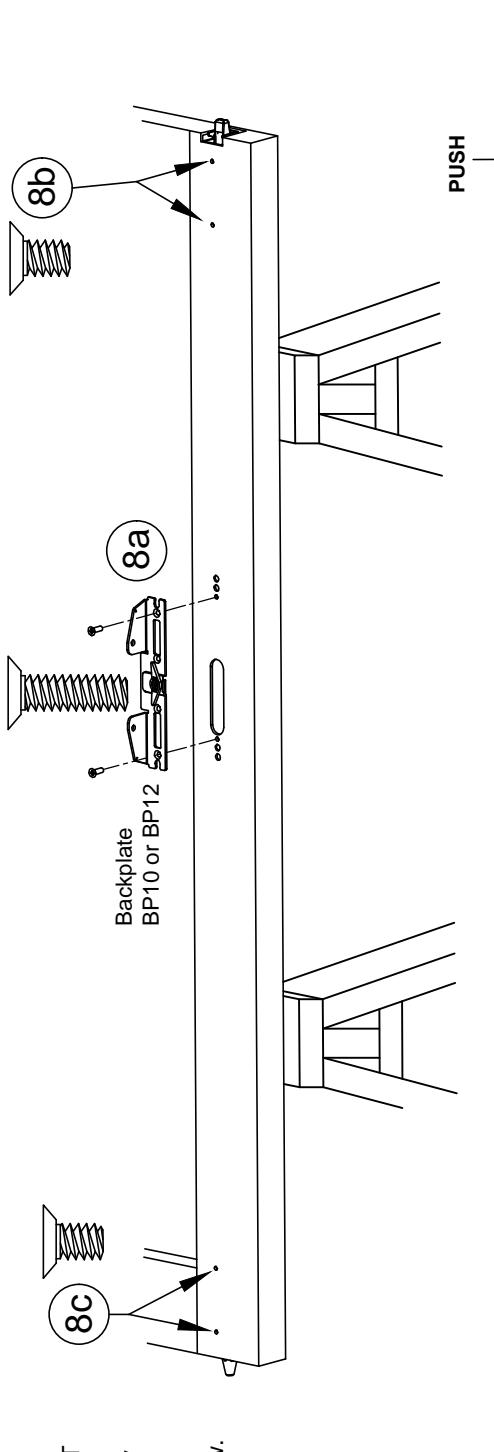
STEP 8: SECURE ROD / LATCH / CENTERLIFT ASSEMBLY TO DOOR
8a. Attach back plate with two screws - DO NOT OVERTIGHTEN.
Assembly hint: Assemble one screw loosely without backplate, then add second screw through backplate. Remove first screw, align backplate and then re-install first screw.
8b. Attach top latch with two screws.
8c. Attach bottom latch with two screws.
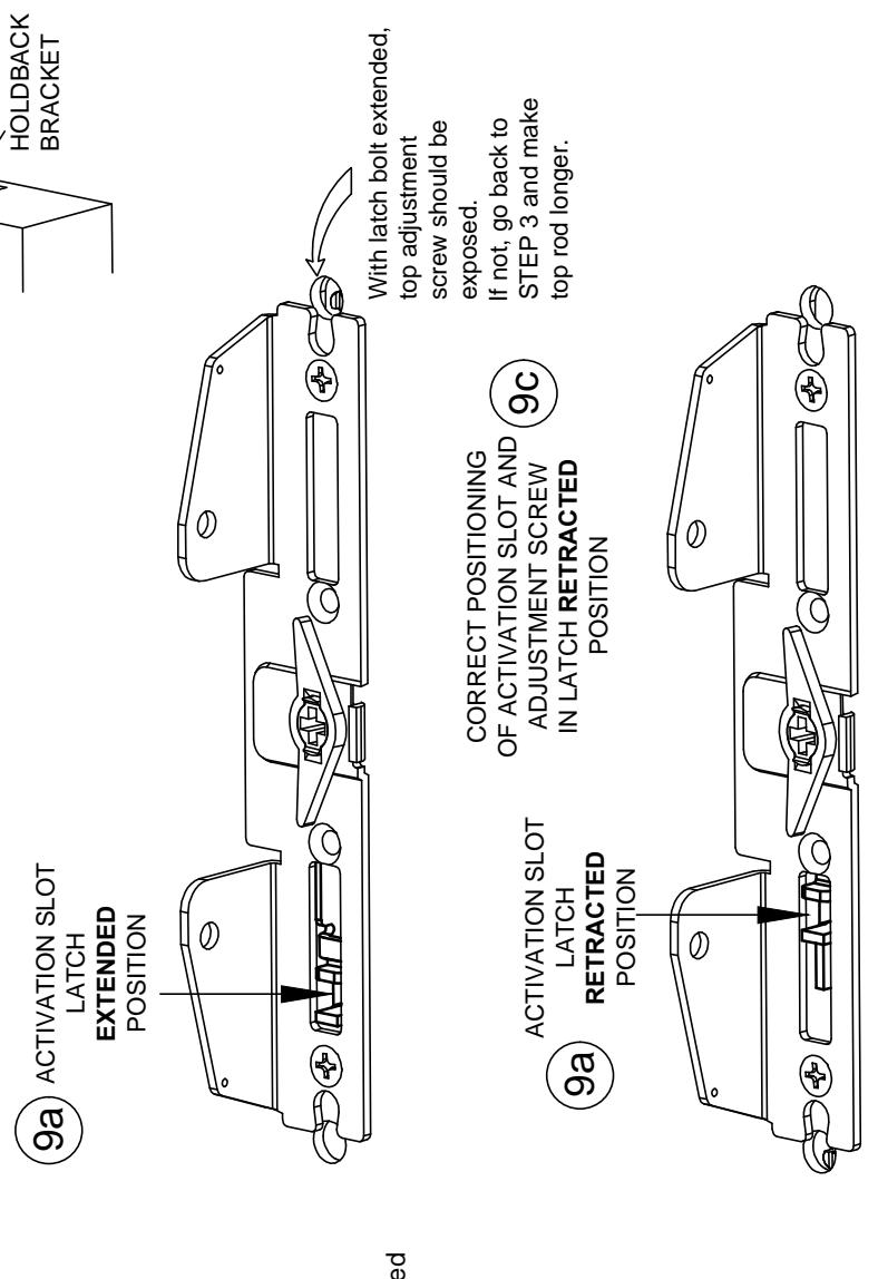
STEP 9: VERIFY CENTERLIFT MECHANISM OPERATION
96
OF ACTIVATION SLOT AND
ADJUSTMENT SCREW IN LATCH EXTENDED
CORRECT POSITIONING
9a. Check current centerlift position using views shown.
9b. To extend latches, push and hold down on the holdback bracket to disengage the retraction feature, then use a screwdriver inserted into the activation slot to gently lower the slot to the extended position as shown.
9c. To retract latches, gently insert a screwdriver into the activation slot and raise the slot to the retracted position as shown.
TROUBLESHOOTING:
If latchbolt is fully extended while activation slot is not fully in the extended position, then top rod is too short. Go back to STEP 3 and correct.
If latchbolt is partially retracted while activation slot is fully in the extended position, then top rod is too long . In this case, latchbolt will be fully retracted before activation slot can travel fully to the retracted position. Go back to STEP 3 and correct.
9d. Bottom bolt drag check:
With top latch in retracted position, check to ensure that bottom bolt is not extending from bottom of door a distance greater than the bottom gap at finished floor (minus the threshold height if threshold is used). If it is, then bottom rod is too long. Go back to STEP 4 and correct.
Upon completion, retract latches before proceeding to Step 10.
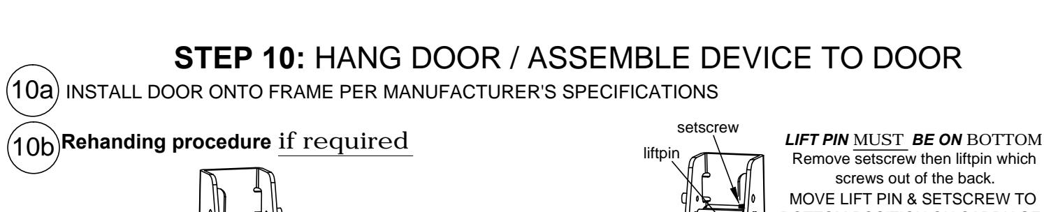
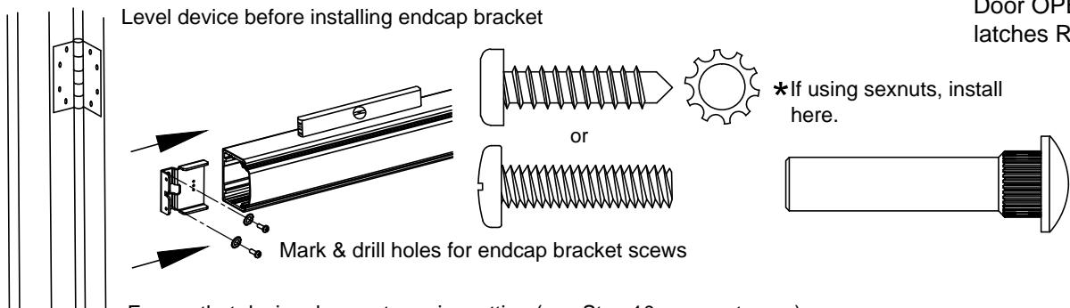
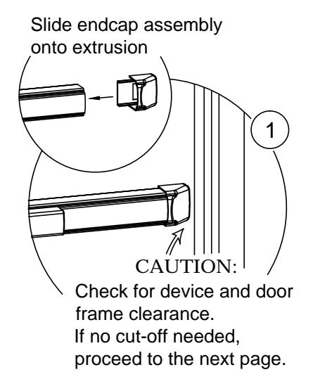
Ensure that device does not require cutting (see Step 10g on next page). Test device fuction after installation of endcap is complete by depressing & releasing pushpad. Action should be smooth with full return of pushpad and latch travel.
CHECKING FOR DEVICE CLEARANCE (Cut-Off procedure if required)
Cut fillerplate and extrusion STRAIGHT & SQUARE to desired length and deburr
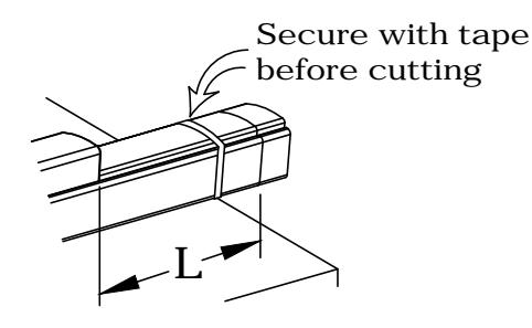
| Minimum | |
|---|---|
| Fillerplate | |
| Length | |
| Type | Length (L) |
| LD | 2-1/2" |
| HD/CD | 3" |
For aluminum Advantex finish cutdown applications:
After cutting, the baseplate extrusion can be reversed to place the cut end inside the head cover. To do so, loosen the setscrew inside the aluminum baseplate extrusion and slide extrusion out, reverse, & slide back in. Tighten setscrew.
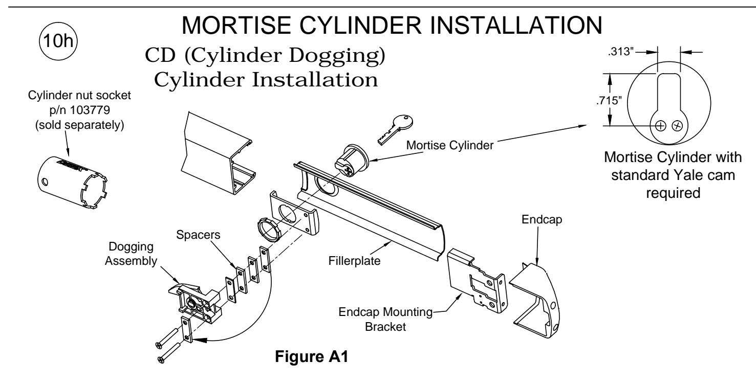
Follow steps "a" through "g" for CD installations
- a. Remove endcap and endcap mounting bracket.
- b. Remove fillerplate.
- c. Remove and discard shipping insert and nut. Loosen (2) screws from dogging assembly.
- d. Install mortise cylinder (sold separately) with large hex nut provided.
- e. Trial fit dogging assembly. If cylinder is too short, remove spacers as necessary and reattach them under the (2) screw heads. Fasten the (2) screws to the rest of the assembly.
NOTE: The key should easily turn in both directions.
- f. Rotate key counterclockwise
- g. Assembly complete. Continue with Panic Hardware instruction.
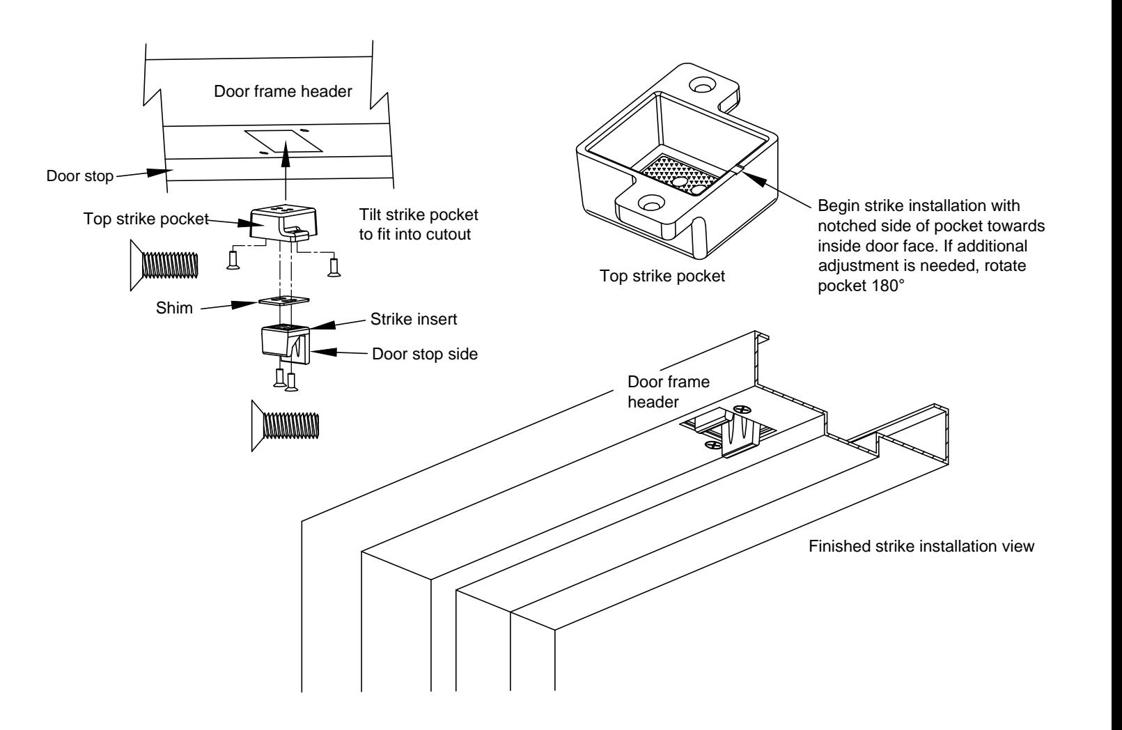
STEP 11: TOP STRIKE INSTALLATION
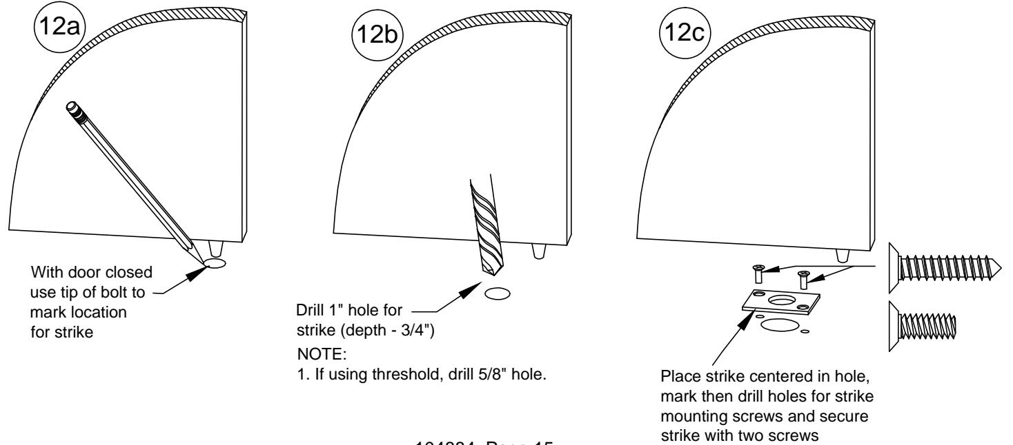
STEP 12: BOTTOM STRIKE INSTALLATION (Disregard if TRO device is being installed)
BOTTOM STRIKE HOLE LOCATION & DRILLING
STEP 13: FINE LATCH ADJUSTMENT
- 13a. Ensure that latches are fully retracted. Gently close door. Latches should extend when door is closed.
- 13b. Depress pushpad and open door. Top latch should clear top strike & bottom bolt should not drag. Latches should remain in retracted position with pushpad released.
FINE LATCH ADJUSTMENT (if needed)
(± 3/8" adjustment possible on both top & bottom rods independently. See diagram below.)
- 13c. Top strike fine adjustment: Adjust strike engagement by either retaining or removing shim. Adjust door tightness by moving insert to desired position. Note that strike pocket can be flipped around to achieve additional adjustment (see step 11).
- 13d: TOP LATCH ADJUSTMENT: With latches extended, turn CCW until the top latchbolt projection begins to visually decrease, then turn CW until latchbolt projects fully. Rotate CW one additional full turn.
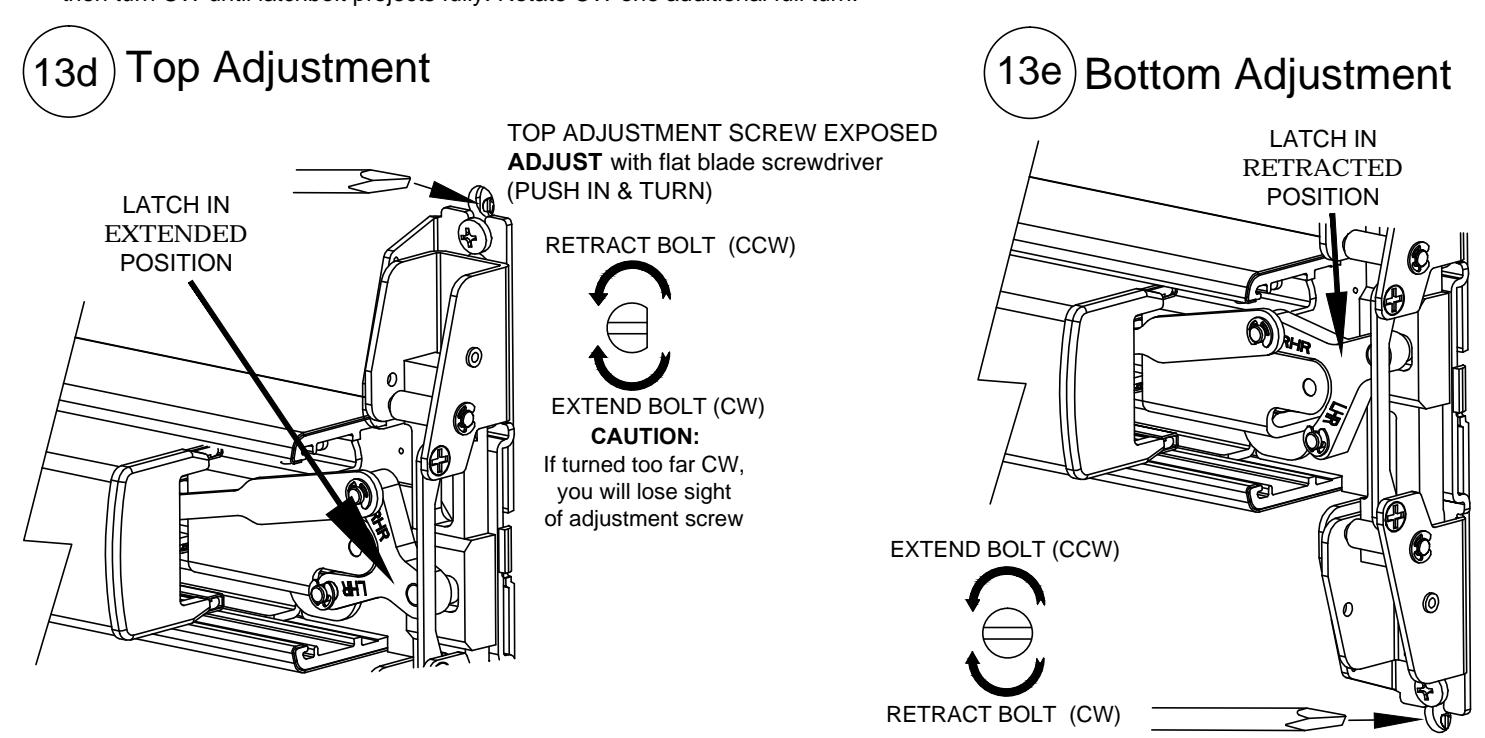
13e: BOTTOM LATCH ADJUSTMENT: With pushpad depressed (retracted position), extend or retract bottom bolt to desired engagement and clearance.
13f. Check device operation. Reference STEP 13a & 13b.
BOTTOM ADJUSTMENT SCREW EXPOSED ADJUST with flat blade screwdriver (PUSH IN AND TURN)
| DEVICE OPERATION TROUBLESHOOTING | ||
|---|---|---|
| SYMPTOM | POSSIBLE CAUSE | SOLUTION |
| Device not latching | Bottom bolt is not properly aligned with bottom strike hole. | Modify bottom strike hole for fit. |
| when door closes | Top strike insert is not installed or not correctly aligned with the holdback. | Install and/or position strike insert per instructions. |
| Through fasteners for trim (if applicable) are interfering with internal centerlift assembly. | Loosen and re-position through screws to clear. | |
| Rods improperly adjusted | Adjust rods per instructions. | |
| Remove device and re-install per instructions. | ||
| Latches release, but pushpad will not fully depress | Device centercase lift finger not inserted properly into centerlift assembly. | Remove device from backplate and re-install with lift finger correctly inserted. |
| Top adjustment screw is adjusted too far in the retracted direction (CCW). | Rotate top adjustment screw in the extended direction (CW) per FINE LATCH ADJUSTMENT procedure. | |
| Latches are not releasing when pushpad is fully depressed | Device centercase lift finger not inserted properly into centerlift assembly. | Remove device from backplate and re-install with lift finger correctly inserted. |
| Top adjustment screw is adjusted too far in the extended direction (CW). | Rotate top adjustment screw in the retracted direction (CCW) per FINE LATCH ADJUSTMENT procedure. | |
| Bottom adjustment screw is adjusted too far in the extended direction (CCW). | Rotate bottom adjustment screw in the retracted direction (CW) per FINE LATCH ADJUSTMENT procedure. | |
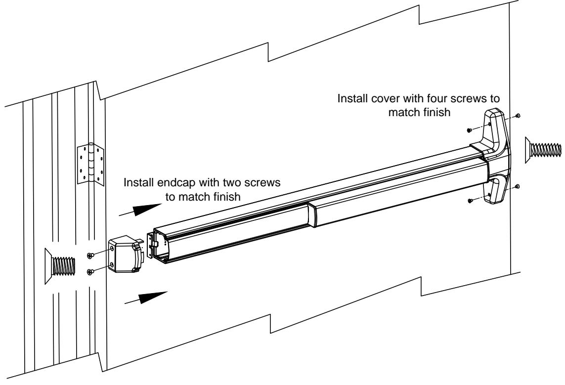
STEP 14: COVER INSTALLATIONS
STEP 15: DOOR POPPER INSTALLATION
FIRE RATED TOP ROD ONLY (TRO) DOORS
A door locking popper is required when a fire door utilizes a top latching mechanism only (TRO). The popper is designed to project a spring loaded bolt into the adjacent frame or door in the event of fire. Detex recommends installing the popper in the edge of the door 12" above the threshold or finished floor. Holes for the popper and plug must be aligned with each other.
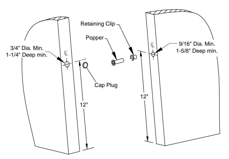
NOTE: Door/Frame reinforcement is required where popper and cap plug are to be installed.
Optional Accessories
Sex Nut Kits
The #1/4-20 kits are available in 3 finishes: Brushed Brass BHMA 606 p/n 105274-2 Oil Rubbed Bronze BHMA 613 p/n 105274-25 Stainless Steel BHMA 630 p/n 105274-9
Catalog No: SN3 (uses screws in hardware kit)
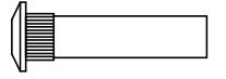
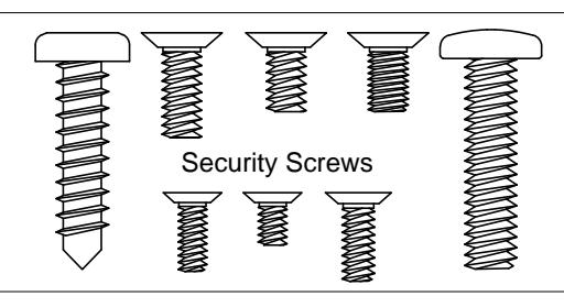
Tamper Kit (Security Kit)
Catalog # & Part #: SSK5
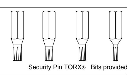
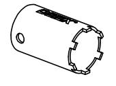
Cylinder nut socket p/n: 103779