Detex Advantex 50xW-Installation Instruction
Open the original PDF document
View PDFΕ

Detex Corporation, 302 Detex Drive, New Braunfels, Texas 78130-3045 830-629-2900 / 800-729-3839 / Fax 800-653-3839 / Text photos only: 830-481-6433 / INTERNET: www.detex.com
INSTALLATION INSTRUCTIONS FOR ADVANTEX® SURFACE VERTICAL ROD 20/21/50/51 SERIES, F20/F21/F50/F51 SERIES, "W" (Weatherized) and "H" (Hurricane) models
ADVANTEX
Dwg #: 101559 (Stainless Steel) 104690 (Aluminum)
| Table of Contents | Page |
|---|---|
| Device parts breakdown view | 2 |
| Device parts breakdown list with part numbers | 3 |
| Hardware List with part numbers & tools required | 4 |
| Door condition check | 5 |
| Use template to locate backplate | 6 |
| Use template to locate top strike | 7 |
| Use template to locate bottom bolt bracket | 8 |
| Hurricane bottom bolt bracket & guard installation | . 9 |
| Use template to locate rod cover brackets | 10 |
| Install Pushpad assembly. Cutdown procedure (if req'd) | 11 |
| Mortise cylinder installation (if req'd) | |
| Level/Secure Pushpad, Rehanding (if req'd) | 13 |
| Top rod installation | |
| Top rod installation continued / Top latch testing | 14 |
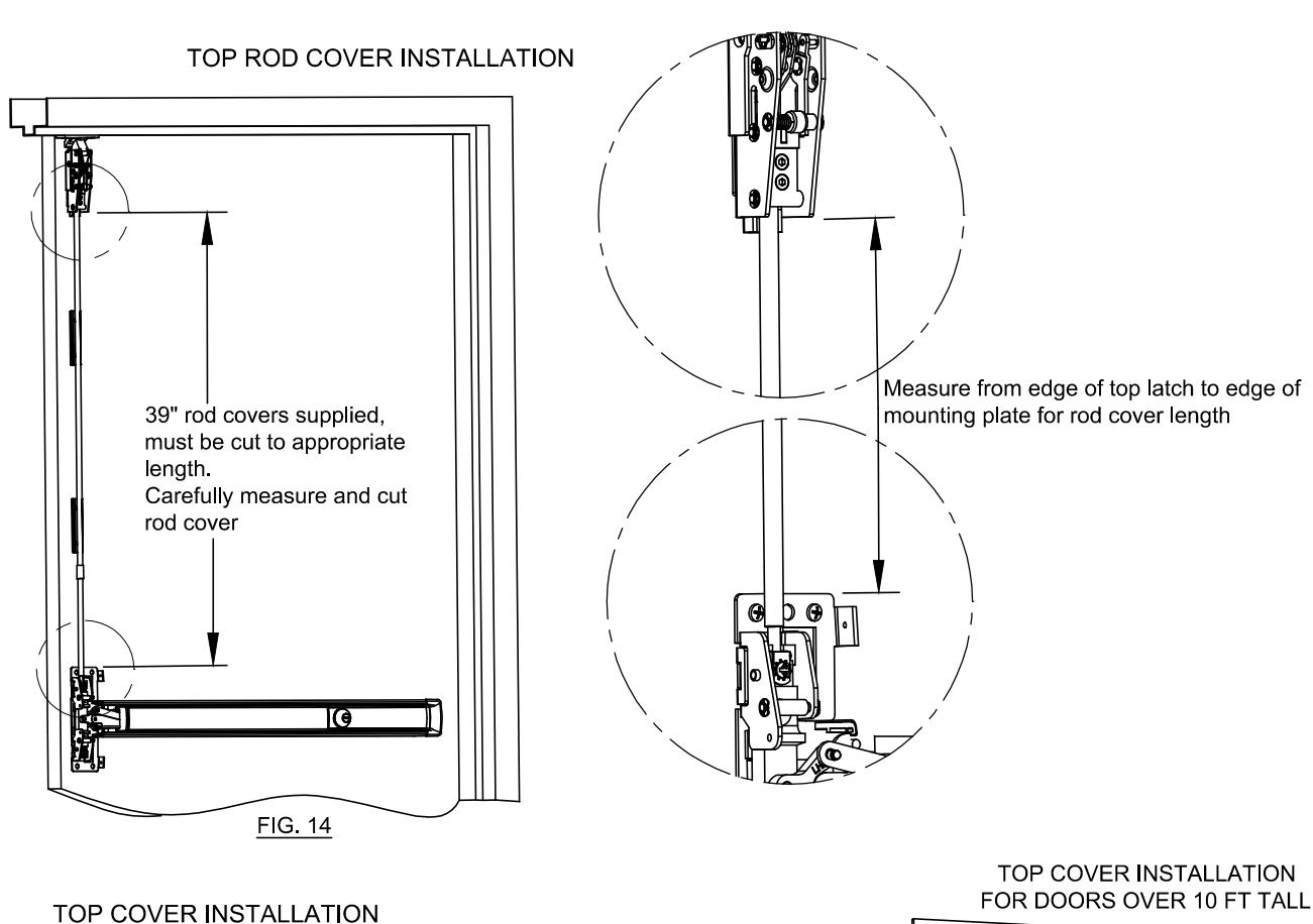
| Top rod cover installation | 15 |
| Bottom rod & dustproof strike installation | . 16 |
| Hurricane bottom rod & dustproof strike installation | . 17 |
| Hurricane bottom bolt testing and adjustment | . 18 |
| Bottom rod cover & Centercase cover installation | 19 |
| Door popper & Narrow stile facia installation | 20 |
| Optional Accessories | 21 |
Should you have a Question/Problem with your Detex device please call Detex Technical Support from the job site at 1-800-729-3839 and choose option 2 on our menu. Please do not return the product to the distributor.
For WARRANTY information, scan code below or go to www.detex.com/warranty
For device installation videos, scan code below or go to www.detex.com/vidoes


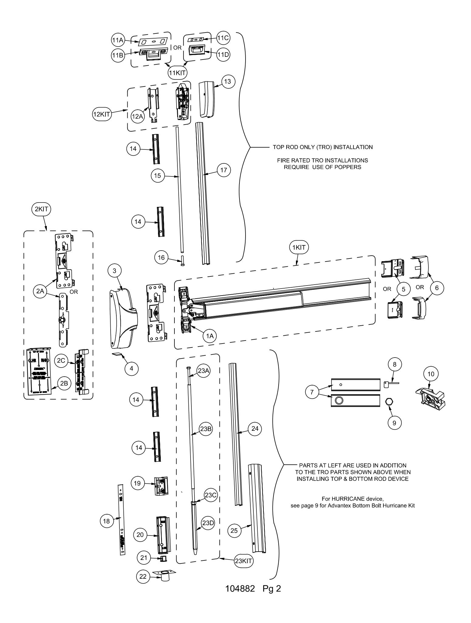
| PARTS BREAKDOWN | ||||
|---|---|---|---|---|
| Item | Order Part # | Description | ||
| 1KIT | 105500-60 | Centercase/Pushpad SubAssembly, 20 series RHR, 36", 630 (includes 1A) | ||
| 105500-61 | Centercase/Pushpad SubAssembly, 50 series RHR, 36", 630 (includes 1A) | |||
| 1A | 101463-1 | Centercase Assembly, RHR, Narrow Stile, 50 series | ||
| 101463-2 | Centercase Assembly, RHR, Wide Stile, 20 series | |||
| | '^ | 101463-3 | Centercase Assembly, LHR, Narrow Stile, 50 series | ||
| 101463-4 | Centercase Assembly, RHR, Wide Stile, 20 series | |||
| 2KIT | 103806-13 | Mounting Plate/Strike Locator Kit, Narrow Stile (includes 2A, 2B, 2C) | ||
| 21(11 | 103806-10 | Mounting Plate/Strike Locator Kit, Wide Stile (includes 2A, 2B, 2C) | ||
| 2A | 100696-1 | Mounting Plate, BP2, Narrow Stile | ||
| 100697-1 | Mounting Plate, BP1, Wide Stile | |||
| 2B | 101511-1 | Strike Locator | ||
| 2C | 100720 | Centercase Locator | ||
| 101506-9 | Centercase Cover, Stainless Steel, Wide, 20 series, 630 | |||
| 3 | 101505-9 | Centercase Cover, Stainless Steel, Narrow, 50 series, 630 | ||
| 104640-5 | Centercase Cover, Aluminum, Wide, 20 series, 628 Centercase Cover, Aluminum, Narrow, 50 series, 628 | |||
| 4 | 104602-5 | |||
| - | 101709 | Centercase Cover Cap (for TRO device only) | ||
| 5 | 100147 | Endcap bracket for EC1 (ramped) endcap w/o battery holder Endcap bracket for EC1 (ramped) endcap w/ battery holder | ||
|
101093
104303 |
Endcap bracket for EC2 (flush) endcap w/o battery holder | |||
| 104636 | Endcap bracket for EC2 (flush) endcap w/o battery holder | |||
| 101642-9 | Endcap, EC1 (ramped) Stainless Steel, 630 | |||
| 6 | 104304-9 | Endcap, EC2 (flush) Stainless Steel, 630 | ||
| 104612-1 | Endcap, EC2 (flush) Aluminum, 628 | |||
| 100860-136 | Fillerplate, Subassembly, S&R, Hex Dogging, HD, 20 series, 36", 630 | |||
| | _ | 100860-118 | Fillerplate, Subassembly, S&R, Cylinder Dogging, CD, 20 series, 36", 630 | ||
| 7 | 100860-100 | Fillerplate, Subassembly, S&R, Hex Dogging, HD, 20 series, 36", 628 | ||
| 100860-137 | Fillerplate, Subassembly, S&R, Hex Dogging, HD, 50 series, 36", 628 | |||
| 8 | 100450 | Hex Key (for Hex Dogging) | ||
| 9 | 100783 | Cylinder Nut (for Cylinder Dogging) | ||
| 10 | 102216-2 | Hex Dogging Assembly | ||
| 10 | 102216 | Cylinder Dogging Assembly | ||
| 11KIT | 100855-3 | 97 Strike Kit (includes 11A & 11B) | ||
| 100855-4 | 96 Strike Kit (includes 11C & 11D) | |||
| 11A | 100088 | Strike Shim | ||
| 11B | 100234-1 | Strike, Non-roller | ||
| 11C | 101067 | Strike Shim, Narrow | ||
| 11D | 100330 | Strike, Non-roller, Narrow | ||
| 12KIT | 101464 | Top Latch Assembly (includes 12A) | ||
| 12A | 101393 | Mounting Bracket, Top Latch Assembly | ||
|
13
14 |
101400-9 | Top Latch Cover 630 Rod Cover Bracket | ||
|
101425
104051-1 |
Top Rod, 7' Door, Steel (36.375" long) | |||
| 15 | 104051-1 | Top Rod, 7 Boor, Steel (30.373 long) | ||
| 16 | 104031-2 | 1/4-20 Hex Bolt, 2" long | ||
| 10 | 101374-2 | Top Rod Cover, 7' & 10' applications 630 ( x 2 FOR 10') | ||
| 17 | 101461-9 | Top Rod Cover, 8' applications | ||
| 18 | 101716 | Mylar Bottom Latch Bracket Locator | ||
| 19 | 101428 | Bracket, Top (for bottom rod bolt) | ||
| 20 | 101427 | Bolt Retaining Bracket | ||
| 21 | 101429 | Hex Bushing | ||
| 22 | 101562-9 | Dust Strike | ||
| 23KIT | 101567 | Bottom Rod Assembly (includes 23A-23D) | ||
| 23A | 101574-3 | 1/4-20 Hex Bolt, 3" long | ||
| 23B | 101477 | Bottom Rod | ||
| 23C | PP-5062-37 | 3/8-16 x 21/64 thick Hex Nut | ||
| 23D | 101430 | Bottom Bolt | ||
| 24 | 101486-9 | Bottom Rod Cover 630 | ||
| 25 | 101426-9 | Bottom Cover 630 | ||
Your particular part or configuration may not be shown: Contact Detex technical support at 800-729-3839 (option 2)
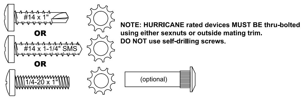
Hardware Table for BASIC device mounting. Additional hardware is provided per the device configuration in kit form and is addressed on the appropriate pages as required
EC1 (ramped) Device hardware kit: p/n 101564-1 for Hex Dogging (HD)
EC1 (ramped) Device hardware kit: p/n 101564-2 for Cylinder Dogging (CD)
EC2 (flush) Device hardware kit: p/n 105724-1 for Hex Dogging (HD)
EC2 (flush) Device hardware kit: p/n 105724-2 for Cylinder Dogging (CD)
| Fastener Part No | Drill Bit community | |
|---|---|---|
|
P/N: 100980
1/4-20 x 1" PPH |
#7 or 13/64" | |
|
P/N: 101621-5
1/4-20 x 1/4" PPH |
#7 or 13/64" | |
|
P/N: 101632-2
10-32 x 5/16" PFHU |
||
|
P/N: 101950-105
8-32 x 5/16" PFHU |
||
| Jumm |
P/N: 100162-106
6-32 x 3/8" PFHU |
|
|
P/N: 103276-63
#14 x 1" PPH SELF DRILLING |
1/8 pilot hole recommended for self-drilling screws | |
|
P/N: PP-5183-110
#14 x 1-1/4" PPH WOOD SCREW |
||
|
P/N: 103276-41
#10 x 1" PPH SELF DRILLING |
||
|
P/N: PP-5183-68
#10 x 1" PPH |
||
|
P/N: PP-5067-25
1/4" Lockwasher |
|
P/N: 101574-1
1/4-20 x 1" BOLT |
|
|---|---|
|
P/N: 101574-4
1/4-20 x 4" BOLT |
|
|
P/N: 101574-5
1/4-20 x 5" BOL |
Т |
|
P/N: 101574-6
1/4-20 x 6" BOLT |
Tools Required:
Power Drill Level Combination Square
Safety Glasses Pencil
Tape Measure Center Punch
3 /16" & 5 /32" Allen Wrenches #2 and #3 Phillips Screw Drivers
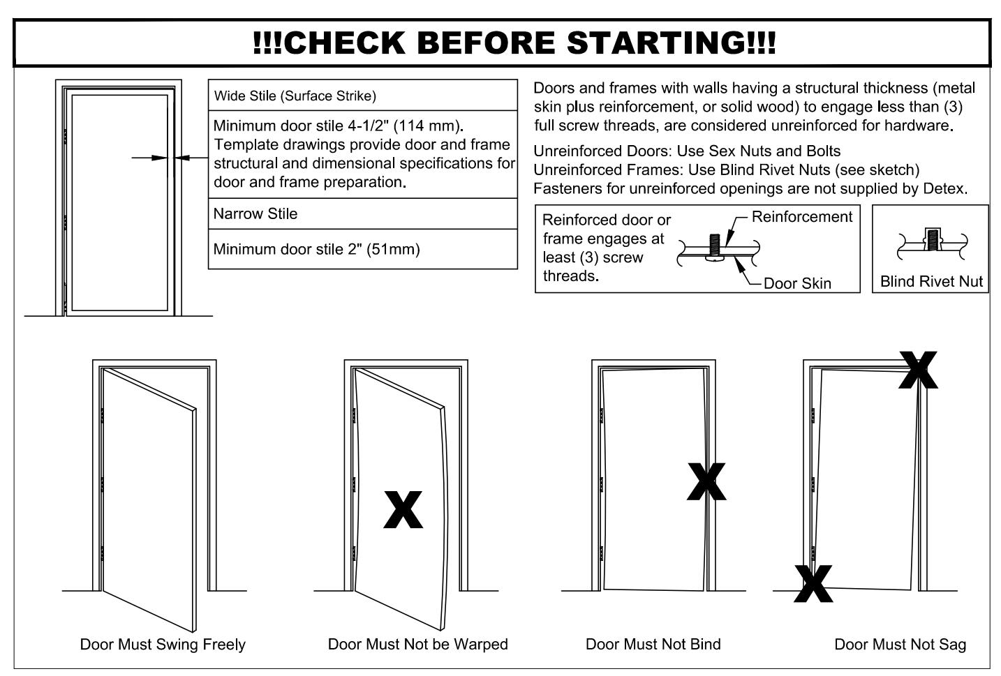
NOTE: 750mm MAXIMUM DOOR WIDTH OPENING FOR EUROPE FOR 36" DEVICE 1000mm MAXIMUM DOOR WIDTH OPENING FOR EUROPE FOR 48" DEVICE THE SAFETY FEATURES OF THIS PRODUCT ARE ESSENTIAL TO IT'S COMPLIANCE WITH EN 1125. NO MODIFICATION OF ANY KIND, OTHER THAN THOSE DESCRIBED IN THESE INSTRUCTIONS ARE PERMITTED.
WHEN PLACING EXIT DEVICES ON EXISTING DOORS, DETEX OFFERS SVR REINFORCEMENT KIT #101063 TO STRENGTHEN THE TOP & BOTTOM BOLT INSTALLATION
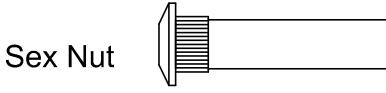
NOTE : LOCAL CODES MAY REQUIRE THROUGH BOLTING. SEX NUTS ARE NOT INCLUDED WITH THIS DEVICE. SEX NUTS CAN BE PURCHASED SEPARATELY.
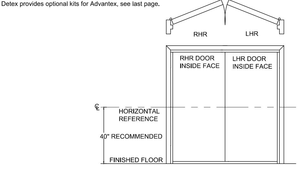
104882 Pg 5
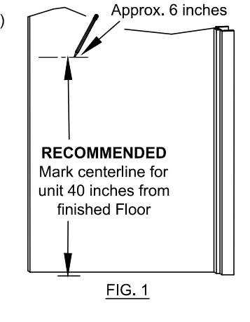
MOUNTING PLATE & STRIKE INSTALLATION:
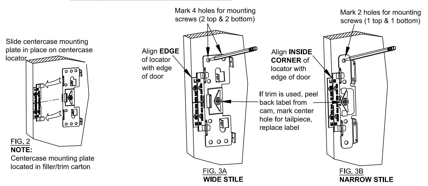
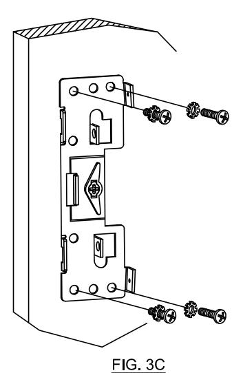
The installation of a wide or narrow device is the same except for the mounting plate (see illustration below) and plastic locator positions when marking holes. This instruction depicts a BP1 installation unless noted otherwise.
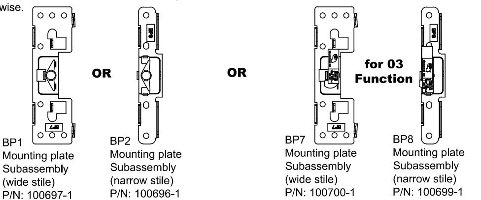
MOUNTING PLATES SHOWN ABOVE FOR USE WITH LEVER TRIM
RETROFIT NOTE : DO NOT RE-USE OLD MOUNTING PLATE!
NOTES:
Plastic locators are provided with an extra 1/2" flap to allow better centering of the device on the stile or can be used when installing 1/2" Astragal to give equal backset from the door edge.
IF OUTSIDE TRIM IS USED, REFER TO OUTSIDE TRIM INSTRUCTIONS NOW.
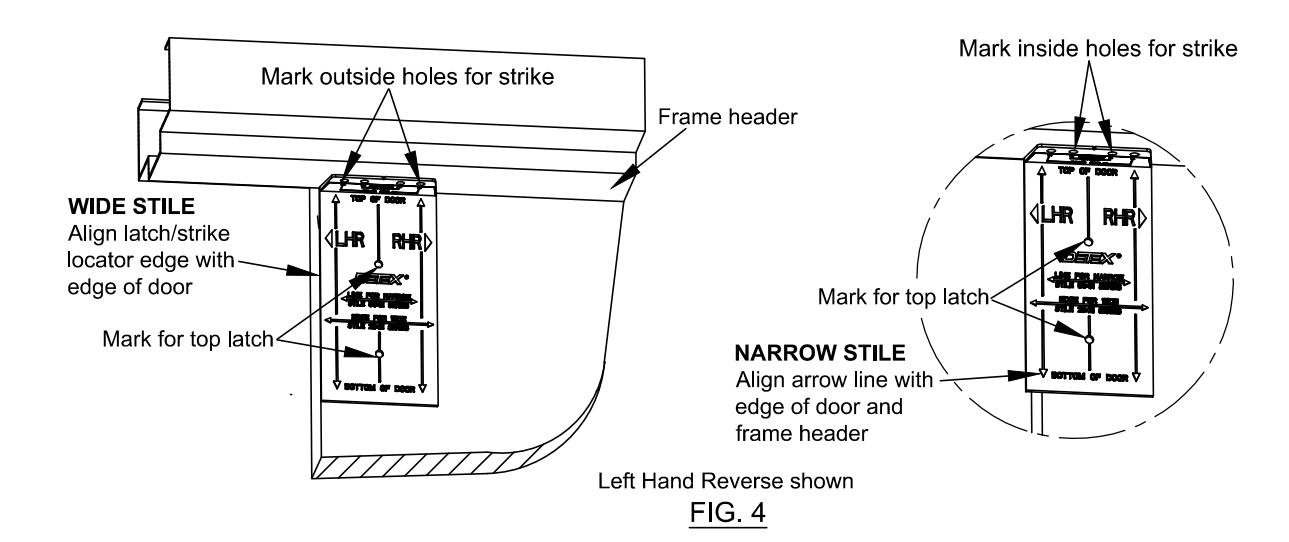
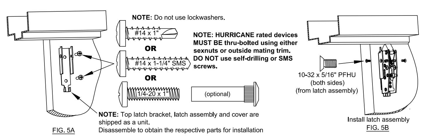
INSTALL TOP STRIKE
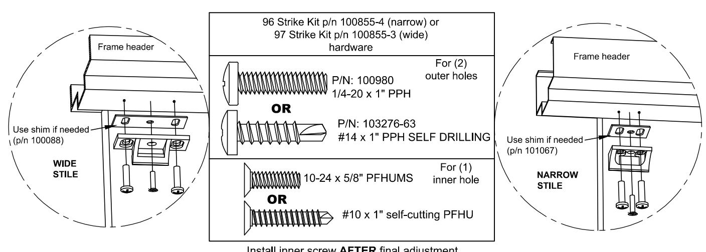
Install inner screw AFTER final adjustment (See Pg. 13 Adjustment/Troubleshooting, Note #4)
FIG. 5C
104882 Pg 7
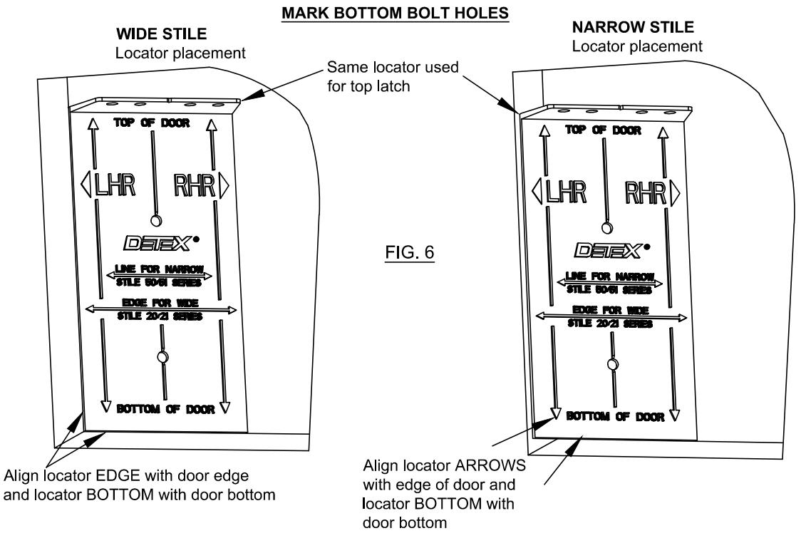
INSTALL BOTTOM BOLT BRACKET:
NOTE: Description below is for STANDARD device. For HURRICANE device, see next page.
- 1. Align two bottom holes of mylar bracket locator to previously marked hole locations.
- 2. Adhere mylar bracket locator to door (locator may remain permanently in place).
- 3. Drill through top hole of mylar bracket locator.
- 4. Drill holes for bottom bolt bracket.

Unless otherwise noted, parts and hardware shown below are supplied in Advantex Bottom Bolt Hurricane Kit (p/n 103562-1)
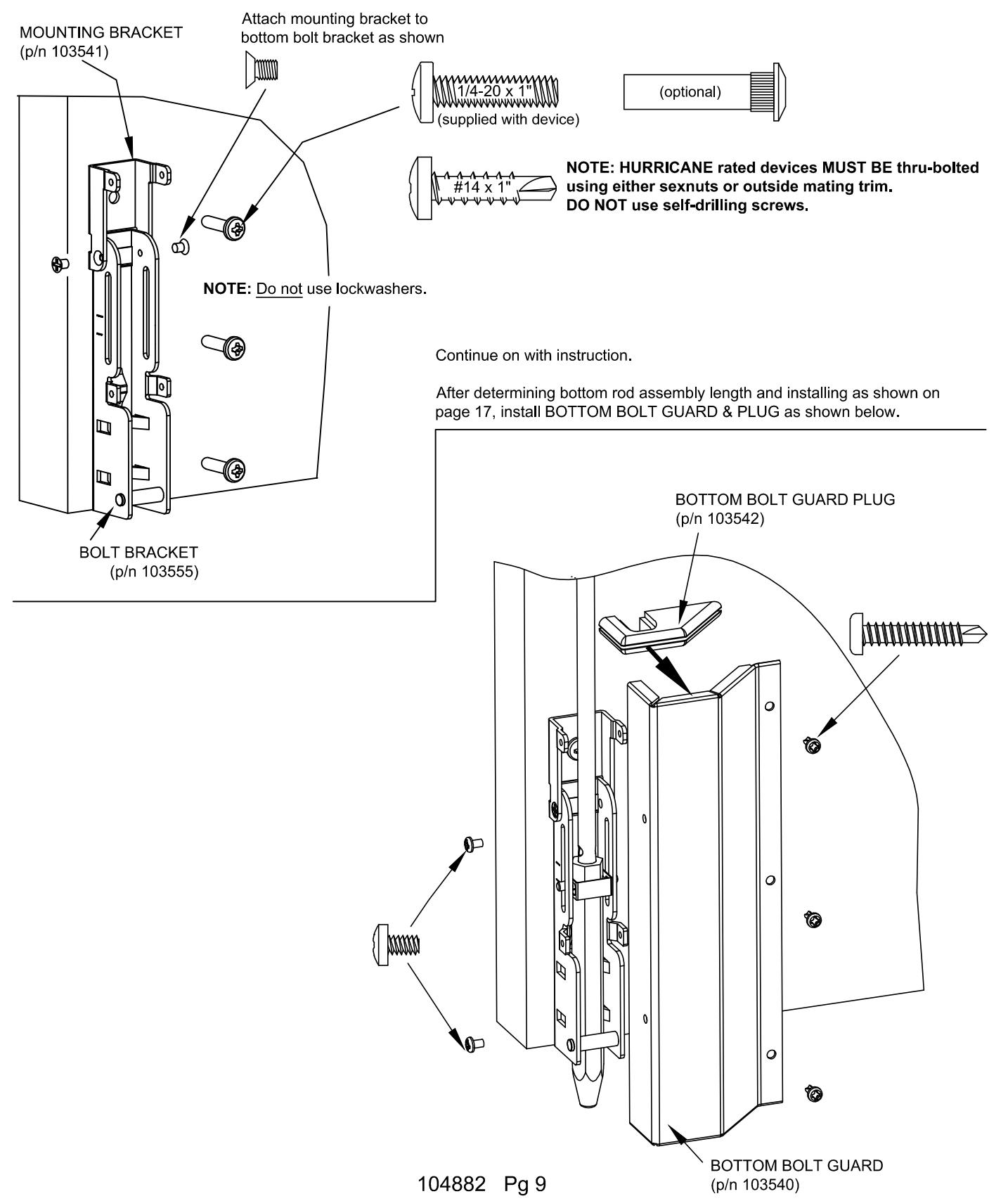
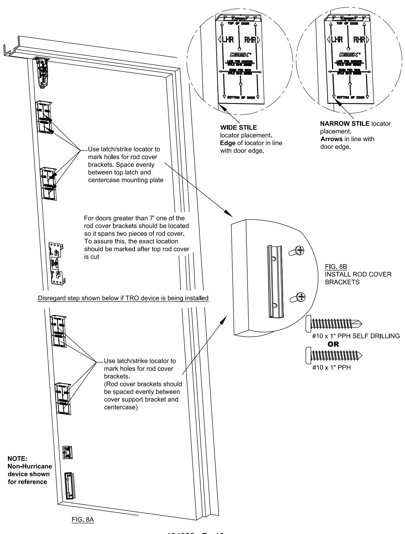
104882 Pg 10
CHECKING FOR DEVICE CLEARANCE (Cut-Off procedure if required)
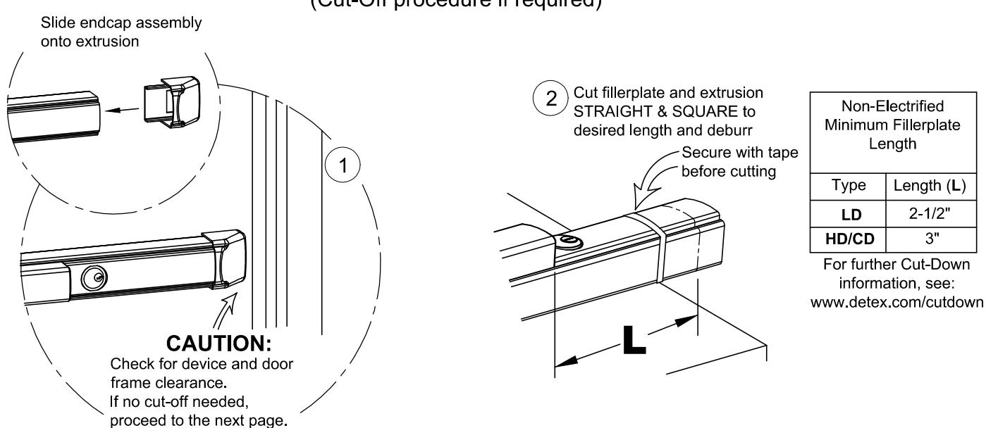
For aluminum Advantex finish cutdown applications:
After cutting, the baseplate extrusion can be reversed to place the cut end inside the head cover. To do so, loosen the setscrew inside the aluminum baseplate extrusion and slide extrusion out, reverse, & slide back in. Tighten setscrew.
MORTISE CYLINDER INSTALLATION CD (Cylinder Dogging) Cylinder Installation
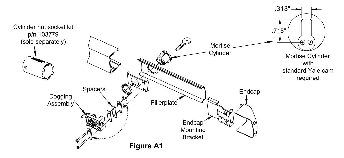
Follow steps "a" through "g" for CD installations
- a. Remove endcap and endcap mounting bracket.
- b. Remove fillerplate.
- c. Remove and discard shipping insert and nut. Loosen (2) screws from dogging assembly.
- d. Install mortise cylinder (sold separately) with large hex nut provided.
- e. Trial fit dogging assembly. If cylinder is too short, remove spacers as necessary and reattach them under the (2) screw heads (See Figure A1). Fasten the (2) screws to the rest of the assembly. NOTE: The key should easily turn in both directions.
- f. Rotate key counterclockwise
- g. Assembly complete. Continue with Panic Hardware instruction.
NOTE: LINK SHOULD ALWAYS BE IN TOP POSITION
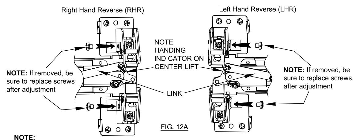
If link is not in uppermost position on the centerlift, carefully remove "E" clips and reposition link on top pin of the centerlift and replace "E" clips. (An additional "E" clip is provided on opposite link pin.)
Verify carriage moves up and down smoothly when pushpad is depressed and released.

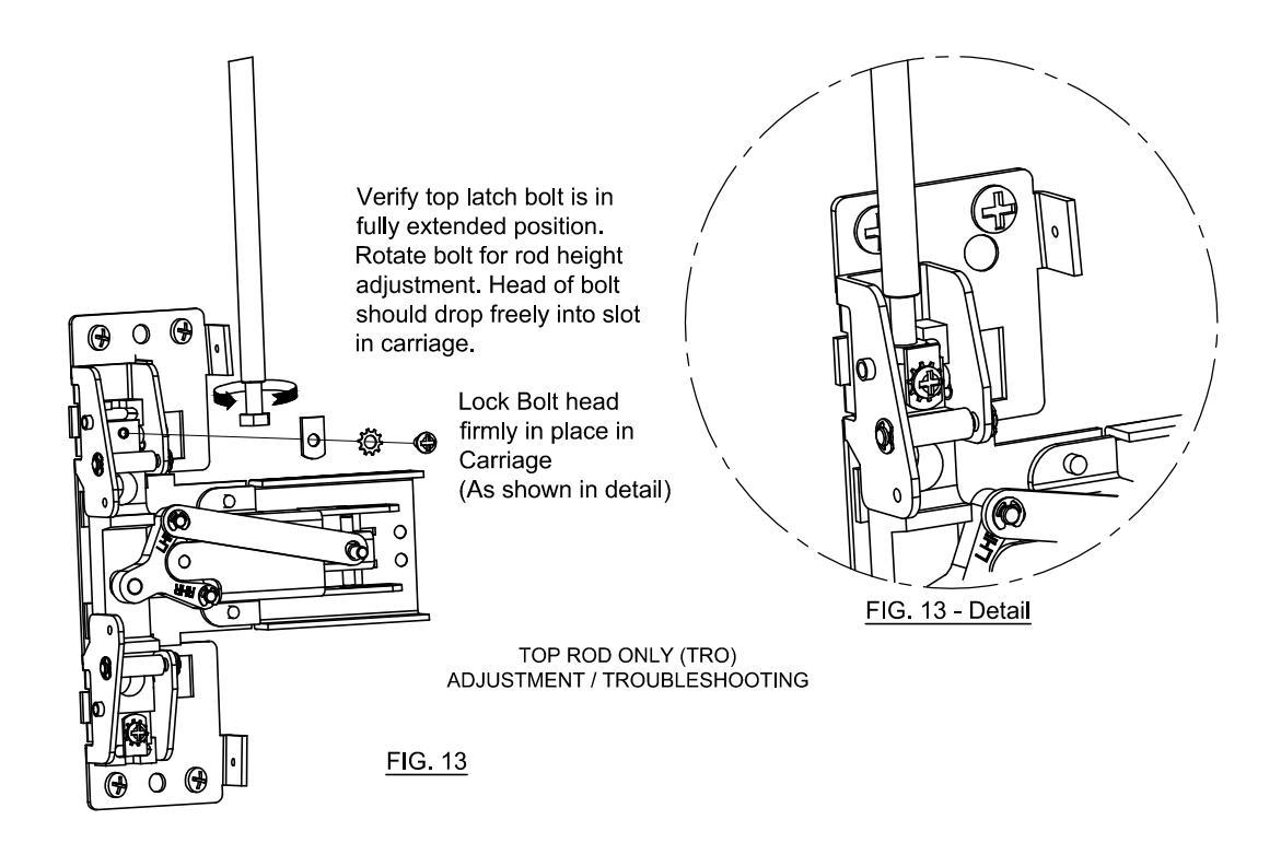
TOP LATCH TESTING AND ADJUSTMENT
1. Close the door.
The holdback lever should engage the backside of the strike, allowing the latchbolt to extend. The device should latch securely and latchbolt should fully project into the strike cavity.
2. Press the pushpad.
The latchbolt should retract fully and smoothly from the strike as the door opens.
3. Release the pushpad.
The latchbolt should remain retracted until the door is closed.
4. Once the latchbolt operation has been evaluated, the strike should be checked and adjusted to allow the door to be held snug to the frame but allow free movement of the latchbolt during normal operation. When the appropriate position has been set. a third hole should be marked, drilled and tapped for a #10 screw. Lock the strike in position with this third screw. (See Fig. 5C)
NOTE: For centerline heights significantly higher or lower than the specified 40", it may be necessary to use shorter or longer adjustment hexbolts in the rods to effect appropriate adjustment. Additional adjustment screw lengths have been packaged in the hardware kit to provide heights up to 41-1/2" and down to 36-1/2". For some door heights it may be necessary to cut the rod. Be sure to cut the un-threaded end.
TROUBLESHOOTING
Latchbolt does not completely relatch when closing the door Loosen the strike screws and adjust the strike to allow the latchbolt to completely extend into the strike. Tighten the screws and add the third center screw to lock the strike in place.
2. Latchbolt fails to retract when pushpad is pushed
Check centercase assembly and verify that the link is attached to the TOP post of the centerlift assembly (see Fig. 12A).
3. Latchbolt is slow or does not completely extend when door closes.
Check position of rod dampener and move it below rod cover bracket.
Check rod adjustment (Fig 13).
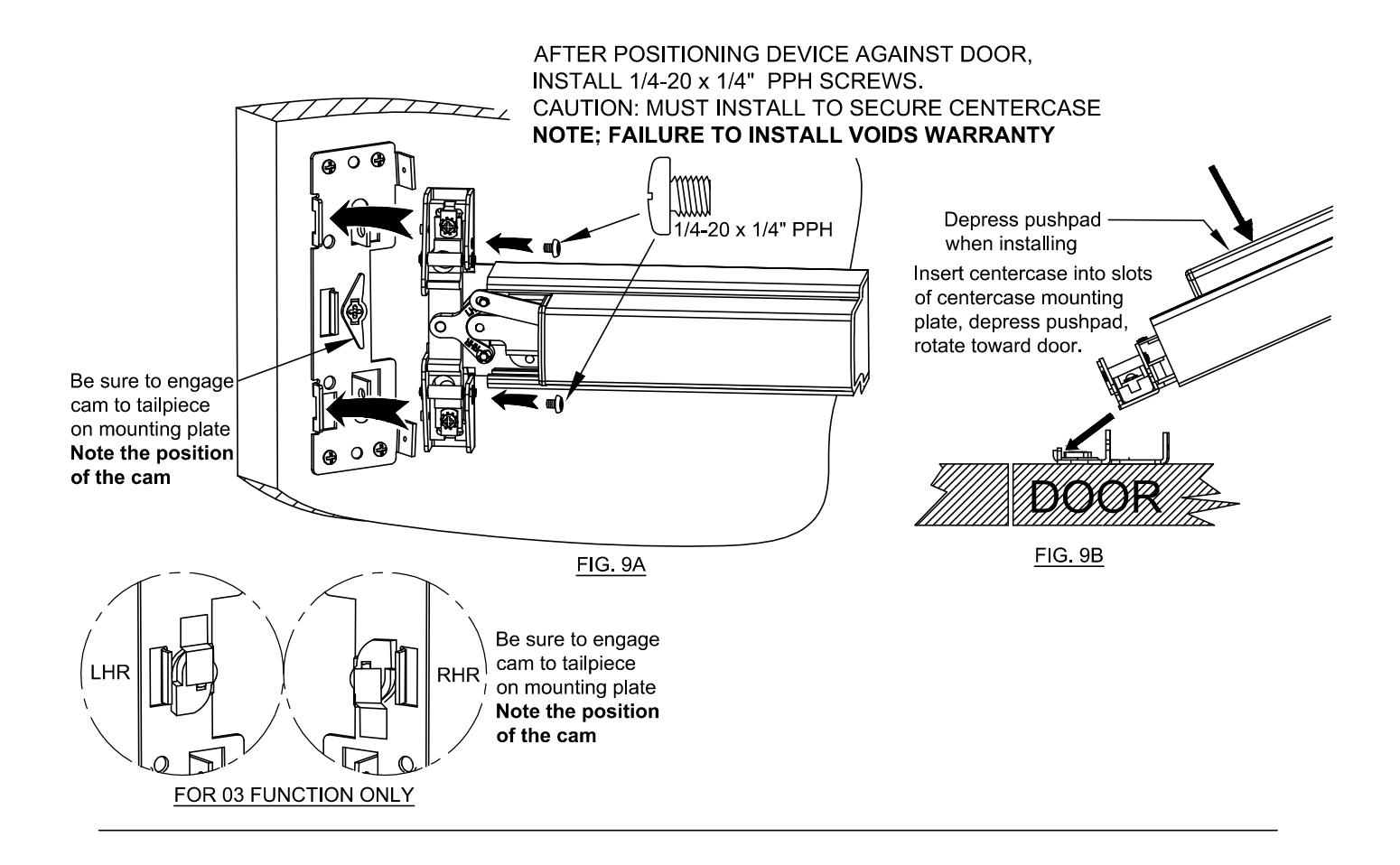
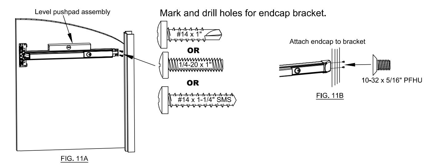
Check centercase, verify that the 1/4-20 x 1/4" screws have been installed (See Fig. 9A).
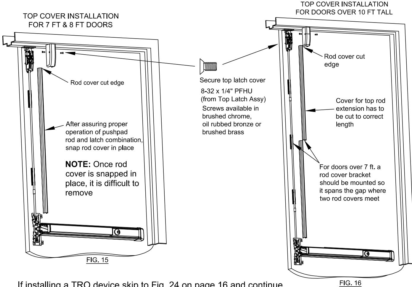
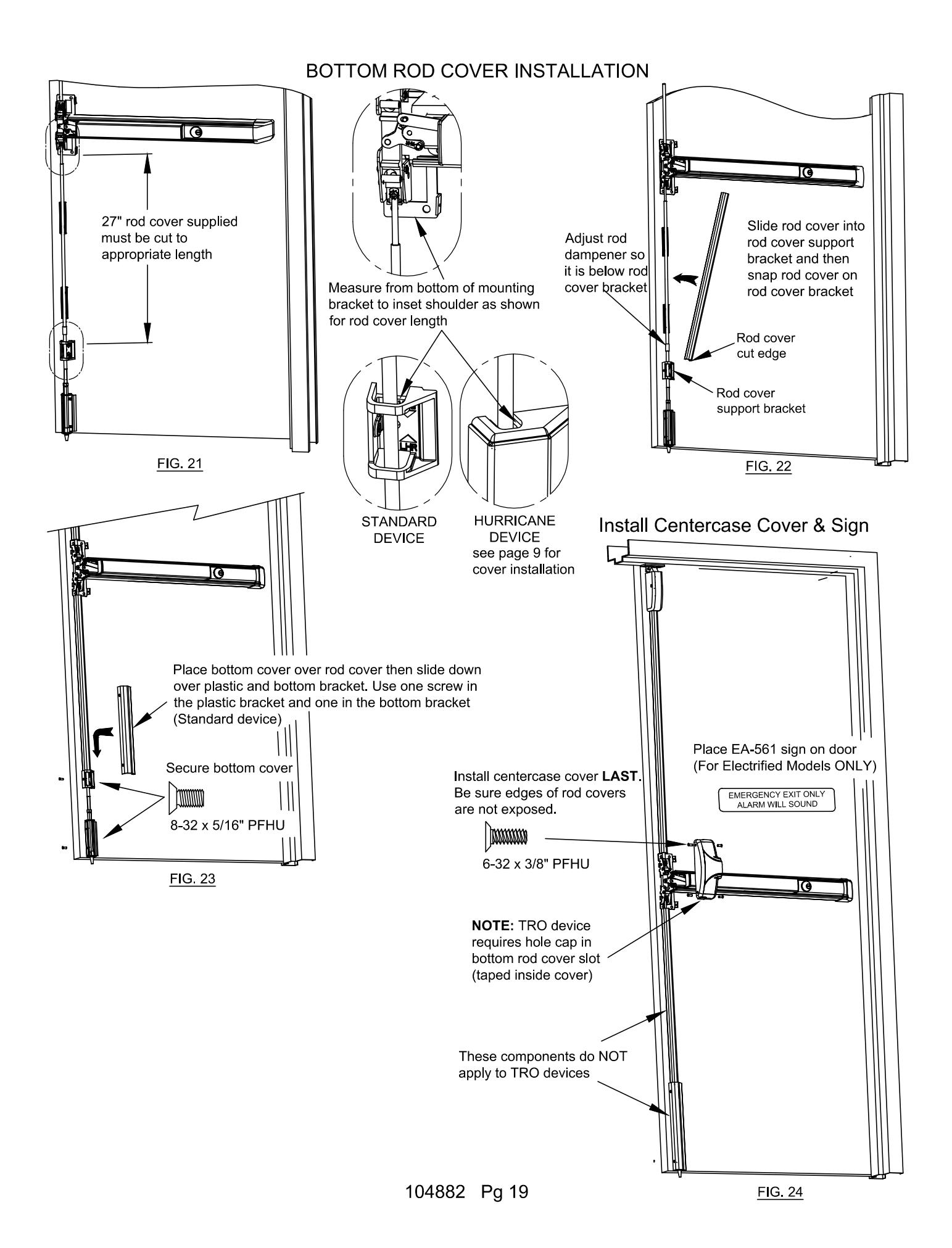
If installing a TRO device skip to Fig. 24 on page 16 and continue 104882 Pg 15
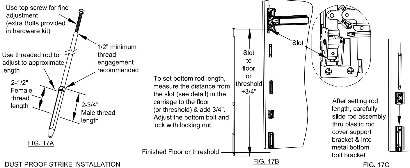
INITIAL BOTTOM ROD ADJUSTMENT:
NOTE: Description below is for STANDARD device. For HURRICANE device, see next page.
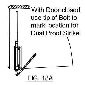
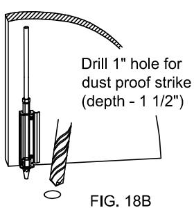
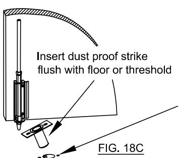
Drill holes for strike mounting screws and secure strike with screws provided with dust proof strike.
Drill 3/16" hole for plastic anchor. Drill 5/16" hole for metal anchor.
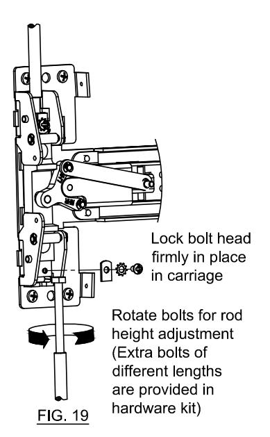
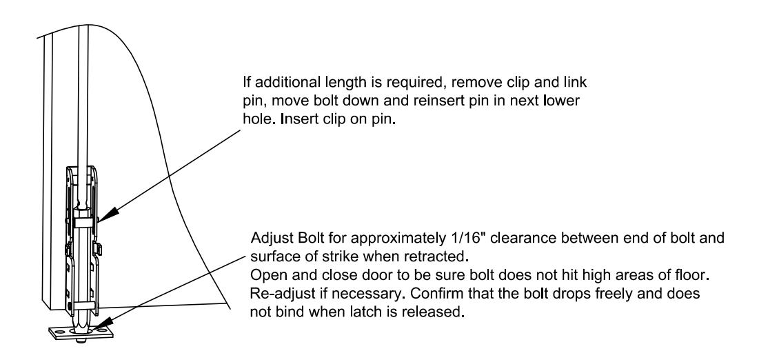
If additional length is required, adjust bottom bolt to required length. Be sure to tighten the locking nut. Adjust Bolt for approximately 1/16" clearance between end of bolt and surface of strike when retracted. Open and close door to be sure bolt does not hit high areas of floor. Re-adjust if necessary. Confirm that the bolt drops freely and does not bind
when latch is released
BOTTOM LATCH Testing and Adjustment Testing
FIG. 20
- 1. Close the door: Bolt should drop into the "dust proof strike" as the door moves into the fully closed position.
- 2. Press the pushpad and open the door: The bottom latch bolt should retract out of the dust proof strike and clear the strike by 1/16" to 1/8". Vertical travel of the bolt should be 3/4".
- 3. Release the pushpad: bolt should remain retracted until the door is closed.
Adjustment
- 1. If bottom bolt drags the floor or hits edge of dust proof strike: Loosen bolt retainer in the carriage assembly and pull bolt from carriage. Screw bolt onto bottom rod one or two turns and return it to the carriage. Test door to assure clearance and secure bolt in carriage by tightening bolt retaining plate.
- 2. If bolt does not completely drop when the latch is released: Check the bottom bolt bracket and be sure the bolt is aligned in the hexagonal plastic bushing. Proper alignment will allow the bolt to freely drop through the bushing.
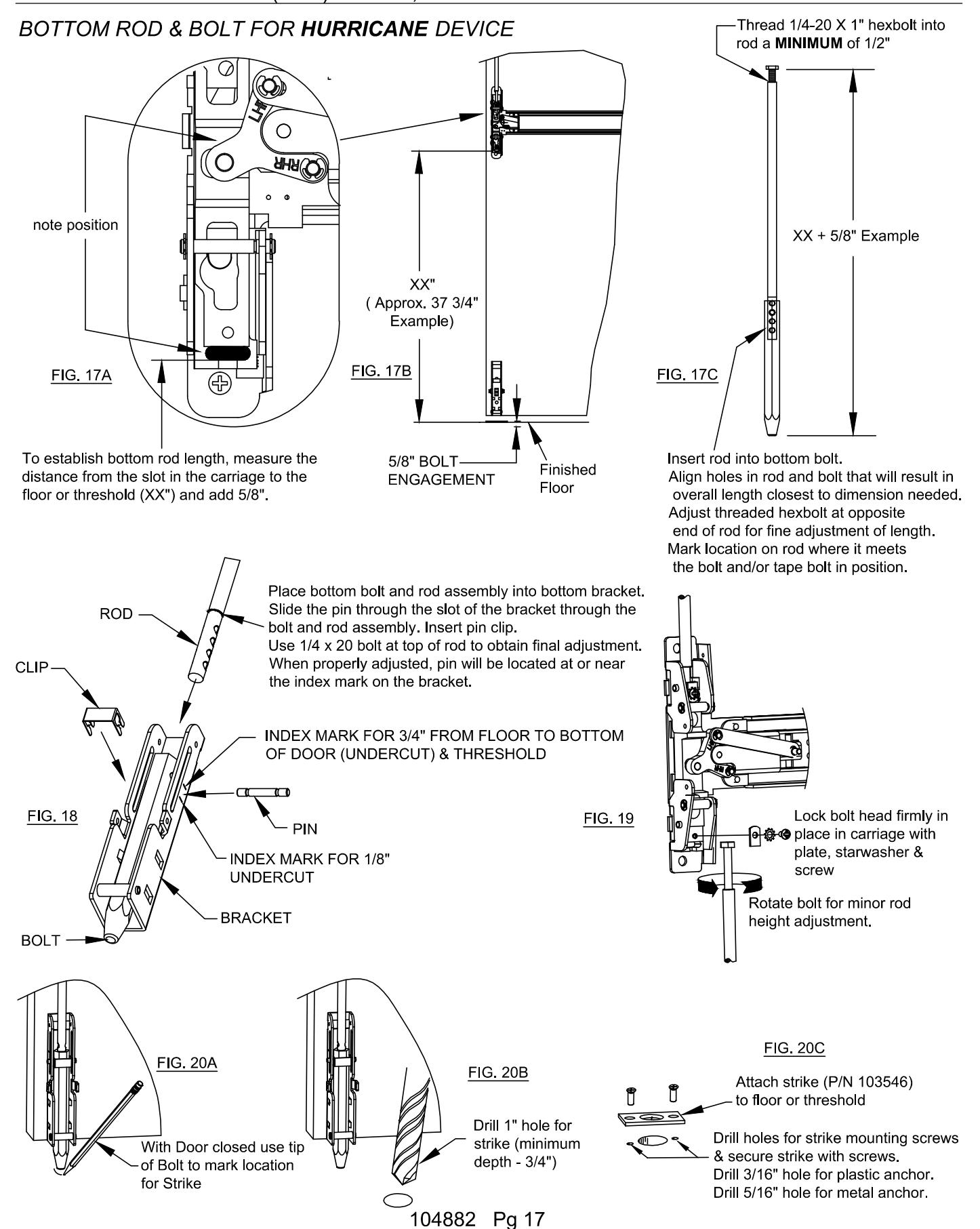
BOTTOM BOLT TESTING AND ADJUSTMENT FOR HURRICANE DEVICE
BOTTOM BOLT Testing and Adjustment
Testing
- 1. Close the door; bolt should drop into the strike as the door moves into the fully closed position.
- 2. Press the pushpad and open the door.
The bottom latch bolt should retract out of the strike and clear the strike by 1/16" to 1/8". Vertical travel of the bolt should be 3/4".
3. Release the pushpad; bolt should remain retracted until the door is closed.
Adjustment
1. If bottom bolt drags the floor or hits edge of strike:
Loosen bolt retainer in the carriage assembly and pull bolt from carriage.
Screw bolt onto bottom rod one or two turns and return it to the carriage.
Test door to assure clearance and secure bolt in carriage by tightening bolt retaining plate.
FIRE RATED TOP ROD ONLY (TRO) DOORS
A door locking popper is required when a fire door utilizes a top latching mechanism only (TRO). The popper is designed to project a spring loaded bolt into the adjacent frame or door in the event of fire. Detex recommends installing the popper in the edge of the door 12" above the threshold or finished floor. Holes for the popper and plug must be aligned with each other.
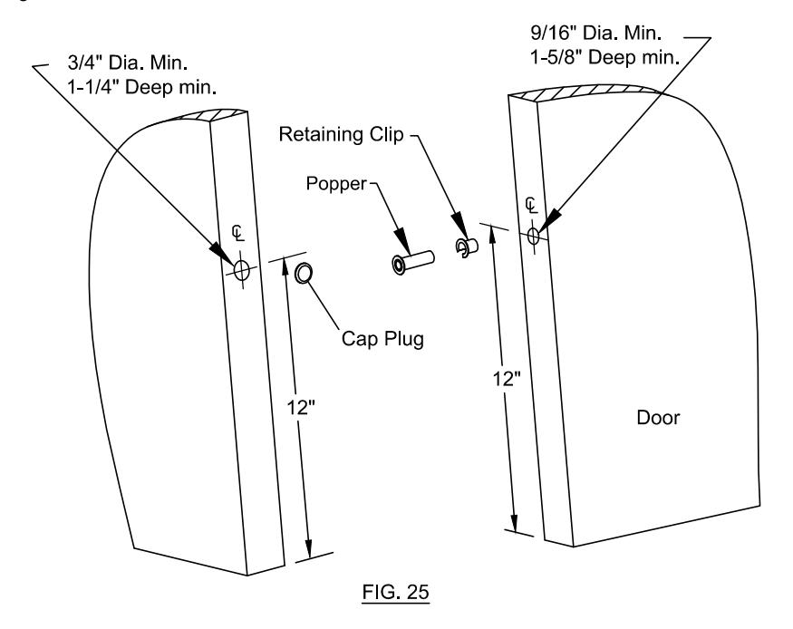
NOTE: Door/Frame reinforcement is required where popper and cap plug are to be installed.
Narrow Stile Endcap Mounting Plate Fascia (For use on Glass Doors) (not used with EC2 endcap)
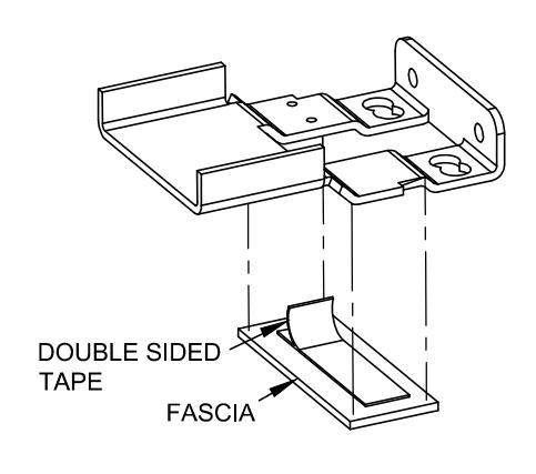
FIG. 26
- a. Remove the endcap mounting bracket.
- b. Attach the fascia with the adhesive tape as shown in Fig. 28.
- c. Re-attach the endcap mounting bracket.
Optional Accessories Glass Bead Kit 00 Catalog No: GB3 -20 Series, 7 foot (p/n 101519-4) 0 GB4 -21 Series, 7 foot (p/n 101519-1) GB5 -50 Series, 7 foot (p/n 101519-14) -51 Series, 7 foot GB6 (p/n 101519-11) -20 Series, 8 foot (p/n 101519-5) GB7 GB8 -21 Series, 8 foot (p/n 101519-2) GB9 -50 Series, 8 foot (p/n 101519-9) GB10 -51 Series, 8 foot (p/n 101519-12) GB11 -20 Series, 10 foot (p/n 101519-6) 0 0 GB12 -21 Series, 10 foot (p/n 101519-3) #1/4-20 X 1-1/2" Screws GB13 -50 Series, 10 foot (p/n 101519-16) Included 0 0 GB14 -51 Series, 10 foot (p/n 101519-13) Wide
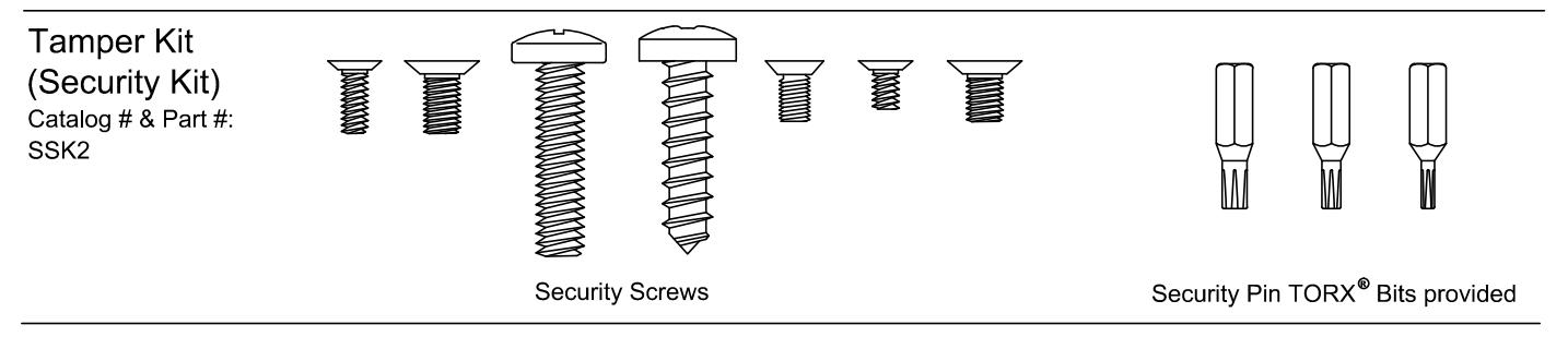
The #1/4-20 kit is available in (4) finishes:
Catalog No: SN1 Brushed Brass BHMA 606 Finish Catalog No: SN1 Oil Rubbed Bronze BHMA 613 Finish Catalog No: SN1 Brushed Chrome BHMA 626 Finish Catalog No: SN1 Stainless Steel BHMA 630 Finish
p/n: 101616-X
Cylinder nut socket
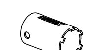
p/n: 103779
The following Models in the series were evaluated by UL: Controlled Exit Panic Devices; Model 20/21 and 50/51. These devices may be suffixed with 01, 02, 03, 08, 09, or 14 followed by C, CN, D, DN, P, PN, W, or WS followed by BP1, BP2, BP7 or BP8, followed by 605, 606, 611, 612, 613, 625, 626, 628, 629, 630, 693, 695 or 711 followed by the RHR or LHR, followed by EA, which may be followed by LD or CD, followed by 605, 606, 611, 612, 613, 625, 626, 628, 629, 630, 693, 695 or 711 followed by 96 or 97, followed by 36 or 48.