Detex Advantex 27-Installation Instructions
Open the original PDF document
View PDF

Detex Corporation, 302 Detex Drive, New Braunfels, Texas 78130-3045 830-629-2900 / 800-729-3839 / Fax 800-653-3839 / Text photos only: 830-481-6433 / INTERNET: www.detex.com
INSTALLATION INSTRUCTIONS FOR ADVANTEX® SURFACE VERTICAL ROD
Drawing: 106400
Surface Vertical Rod Exit Device 27 Series
for Medium to Wide Stile Hollow Metal door applications
| Table of Contents | Page |
|---|---|
| Device parts breakdown view | 2 |
| Device parts breakdown list with part numbers | 3 |
| Hardware List with part numbers & tools required | 4 & 5 |
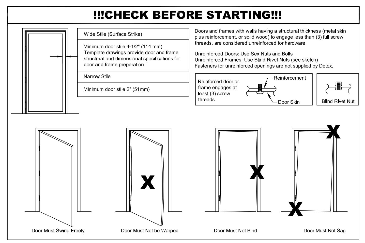
| Door condition check | 6 |
| Prep door and install backplate | 7 |
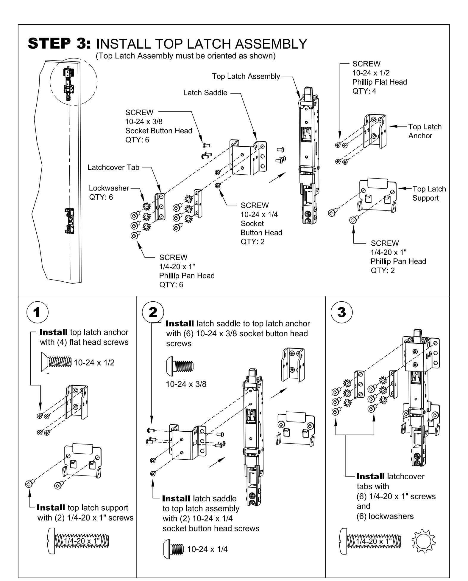
| Install top latch assembly | 8 |
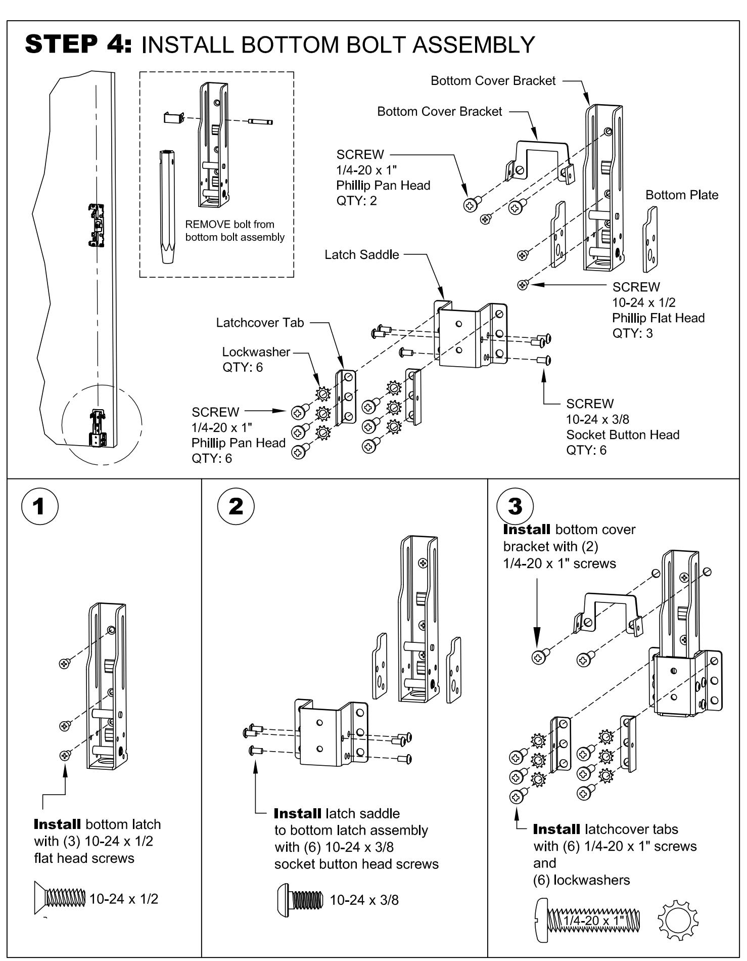
| Install bottom bolt assembly | 9 |
| Install Device | 10 |
| Install mortise cylinder | 11 |
| Check device for clearance | 11 |
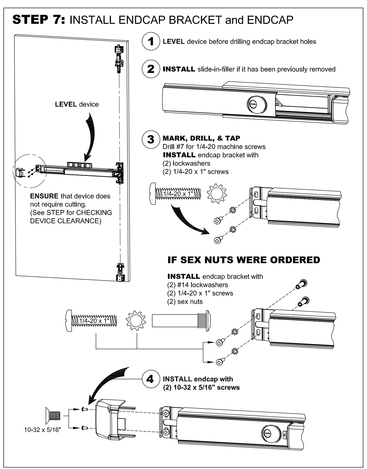
| Install endcap bracket and endcap | 12 |
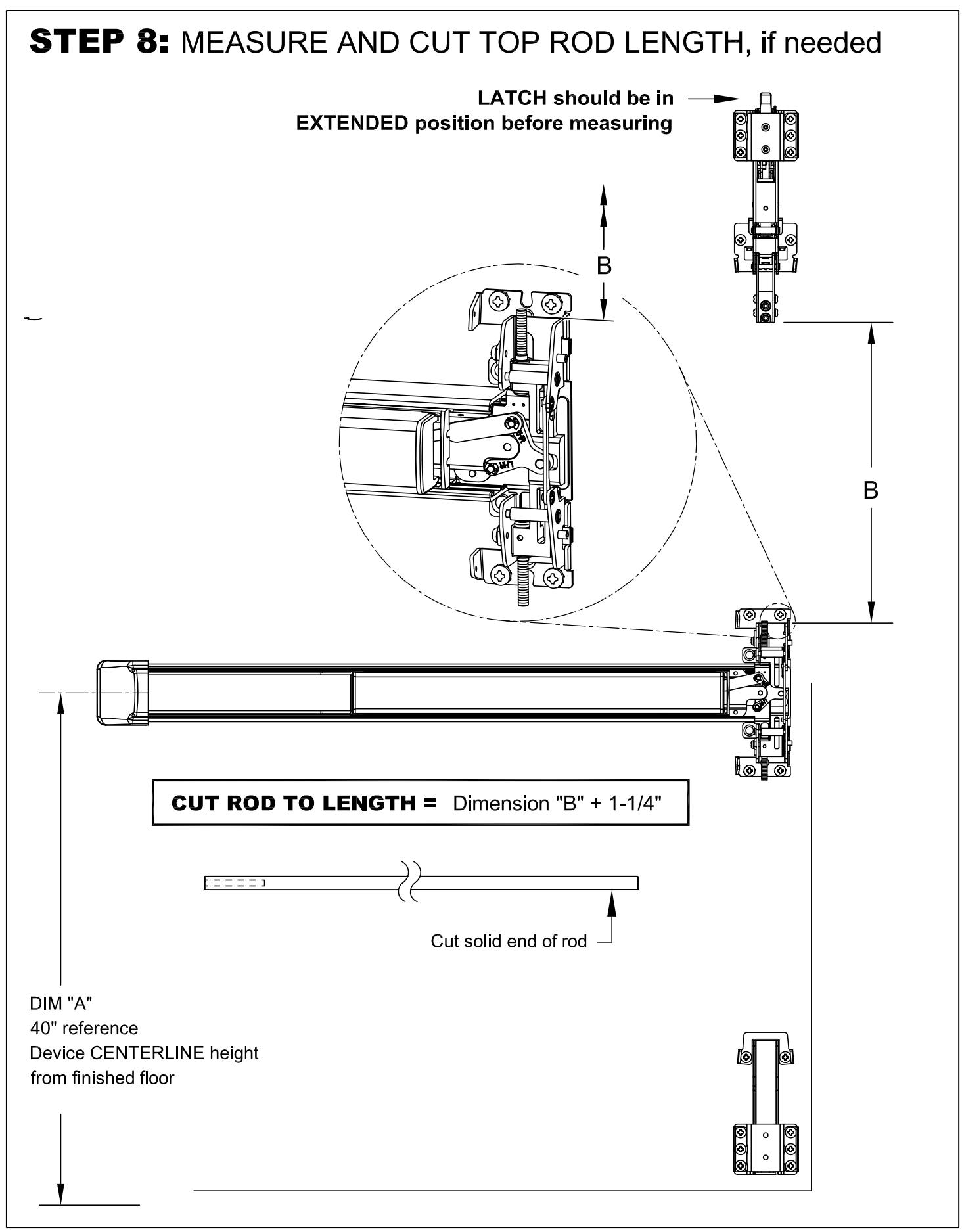
| Measure and cut top rod, if needed | 13 |
| Install top rod | 14 |
| Install bottom rod and bottom bolt | 15 |
| Install top strike | 16 |
| Install bottom strike | 17 |
| Top and bottom rod final adjustment | 18 |
| Top latch operation | 19 |
| Device operation troubleshooting | 19 |
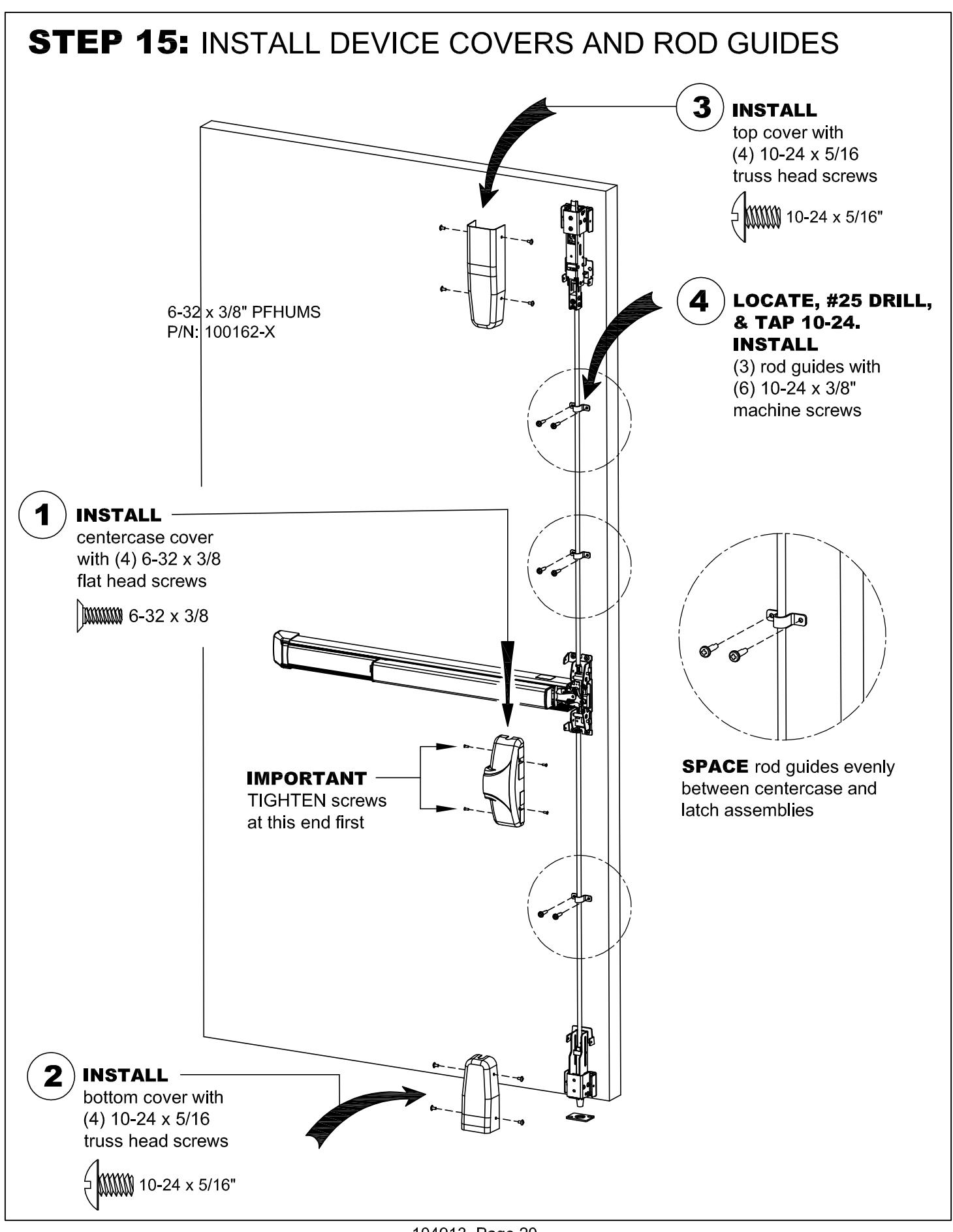
| Install device covers and rod guides |
Should you have a Question/Problem with your Detex device please call Detex Technical Support from the job site at 1-800-729-3839 and choose option 2 on our menu. Please do not return the product to the distributor.
For WARRANTY information, scan code below or go to www.detex.com/warranty

Owner's Copy
For device installation videos, scan code below or go to www.detex.com/videos

Device Parts Breakdown View
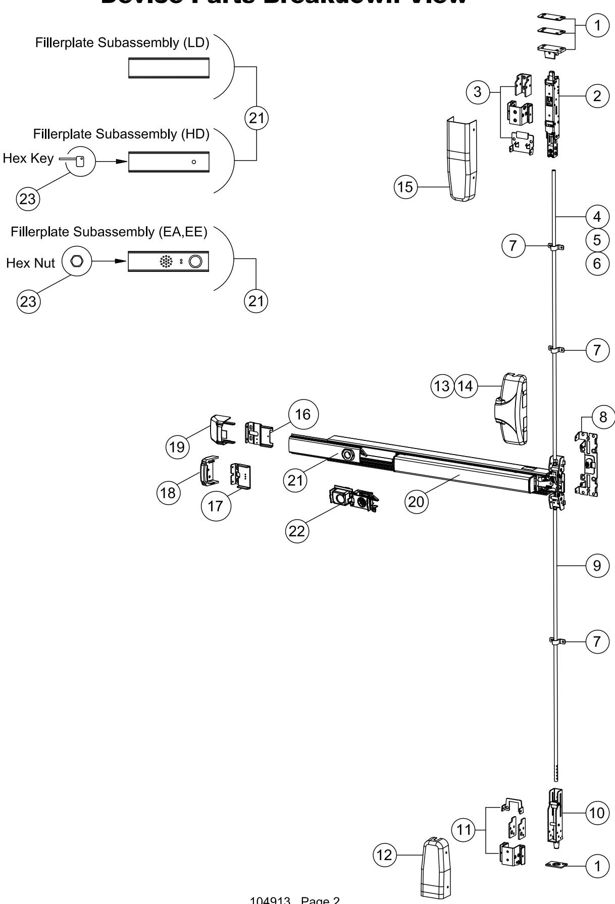
Device Parts Breakdown Part Numbers
| ITEM | DESCRIPTION | QTY |
PART
NUMBER |
|---|---|---|---|
| 1 | Strike kit, ADV 27 | 1 | 106405-1 |
| 2 | Top latch assembly, FEMA, SVR, Fire | 1 | 105984-4 |
| 3 | Top latch mounting kit | 1 | 106407-1 |
| 4 | Top rod, SS, 7' | 1 | 104051-3 |
| Top rod, SS, 8' | 104051-4 | ||
| 5 | Top rod, ADV 27, Latch side, 10' | 1 | 106445 |
| 6 | Top rod, ADV 27, Device side, 10' | 1 | 106446 |
| 7 | Rod guide kit, ADV 27 (3 rod guide) | 1 | 104073-4 |
| 8 | Backplate assembly, wide BP11 | 1 | 104171-1 |
| Backplate assembly, wide BP13 (03 cam) | 1 | 104171-2 | |
| 9 | Bottom rod, V50 | 1 | 103544 |
| 10 | Bottom bolt assembly, SVR, FEMA | 1 | 106140 |
| 11 | Bottom latch mounting kit, ADV 27 | 1 | 106408-1 |
| 12 | Cover, bottom latch, SVR, FEMA | 1 | 106148-9 |
| 13 | Cover, centercase, wide, SVR, SS | 1 | 106141-9 |
| Cover, centercase, wide, SVR, 628 | 1 | 104640-13 | |
| 14 | Cover, centercase, wide, SVR, 693 | 104640-14 | |
| Cover, centercase, wide, SVR, 695 | 104640-15 | ||
| 15 | Cover, top latch, SVR, FEMA | 1 | 106147-9 |
| 16 | Endcap mounting bracket, EC1 | 1 | 100147 |
| 17 | Flush endcap mounting bracket, EC2 | 1 | 104303 |
| 40 | Flush endcap, EC2, SS | 4 | 104304-9 |
| 18 | Flush endcap, EC2, SS, FC | 1 | 104317-9 |
| 40 | Endcap assembly, EC1, SS | 101642-9 | |
| 19 | Endcap assembly, EC1, SS, FC | 1 | 102095-9 |
| S & R Centercase Pushpad LD-RHR | 1 | 105500-146 | |
| 20 | S & R Centercase Pushpad EE-ER-RHR | 105500-63 | |
| S & R Centercase Pushpad ER-EX-RHR | 105500-147 | ||
| S & R Fillerplate subassembly, LD | 100860-161 | ||
| 24 | S & R Fillerplate subassembly, HD | 100860-162 | |
| 21 | S & R Fillerplate subassembly, CD-EA | 1 | 100860-163 |
| S & R Fillerplate subassembly, CD-EE | 100860-164 | ||
| 22 | Dogging assembly, CD-EA | 1 | 100744-2 |
| 22 | Dogging assembly, CD-EE | 105035-2 | |
| 23 | Hex Key molded | . 1 | 100450 |
| Hex Nut cylinder | • | 100783 |
* Note: Parts listed will vary according to product configuration. Mortise cylinder available as an option. Standard Yale type cam required. See Mortise cylinder installation page.
Hardware Table for BASIC device mounting. Additional hardware is provided per the device configuration in kit form and is addressed on the appropriate pages as required
| Fastener Table | ||
|---|---|---|
| Device Mounting | Hardware | |
| Hardware style & size | Description | Used on |
|
1/4-20 x 1" PPHMS
P/N: 100980 |
Used to install backplate & endcap bracket to door | |
|
1/4-20 x 1-1/2" PPHMS
P/N: 100954 |
Used to install backplate & endcap bracket on 2" or greater door thickness with Trim and/or sex nuts | |
|
10-24 x 1/4" PPHMS
P/N: PP-5304-104 |
Used to secure device centercase to backplate | |
| E mm |
10-24 x 5/16" PTHMS
P/N: 106432-305 |
Used to install bottom and top latch covers to latch assemblies |
|
10-32 x 5/16" PFHUMS
P/N: 101632-4 |
Used to install endcap to endcap bracket (Multiple finishes included) | |
|
6-32 x 3/8" PFHUMS
P/N: 100162-306 |
Used to install centercase cover to backplate (Multiple finishes included) | |
|
#14 Lockwasher
P/N: PP-5067-25 |
Lockwashers used with screws A or B | |
|
1/4-20 X 1.60 Sex nut
P/N: 105274-9 |
Used to install backplate and endcap bracket to door If using sex nuts with TRIM: Drill 9/32 hole through interior door face. Drill 1/2 hole through exterior door face. If using sex nuts without TRIM: Drill 3/8 hole through exterior door face. | |
|
Jam nut
P/N: PP-5064-3 |
Used to secure top and bottom rods | |
Tools Required
Power Drill Pencil Pliers Level Center Punch Hack Saw (Chopsaw preferred) Screw Drivers Drill Bit Set Hex Wrench - 1/8 & 5/32 Tape Measure Hammer Masonary Bits - 3/16", 1/4", 5/16", Safety Glasses Tap Wrench 7/8", & 1"
| Fastener Tables | |||
|---|---|---|---|
| Strike Mounting Hardware | |||
|
#10 x 1" self-cutting PFH
P/N: 100109 |
Used to install bottom strike to floor (used with anchors, two styles of anchor included) | ||
|
10-24 x 1/2" PFHUMS
P/N: 100112-108 |
Used to install bottom strike to floor (alternate) | ||
|
1/4-20 x 1" FHSCMS
5/32 Socket HD P/N: 105774-5 |
Used to secure top strike to header | ||
|
1/4-20 x 1" BHSCMS
5/32 Socket HD P/N: 105846-7 |
Used to install top strike to header | ||
|
Anchor
P/N: 101129-1 |
1/4 pilot hole
Used to install bottom strike to floor |
||
|
Alligator Anchor
P/N: 102642-6 |
5/16 pilot hole
Used to install bottom strike to floor |
||
| Top Latch Mounting Kit Hardware | ||
|---|---|---|
| Screw style & size | Description | Used on |
|
1/4-20 x 1" PPHMS
P/N: 100980 |
Used to install latch cover tabs, saddle, and top latch support to door | |
|
10-24 x 1/2" PFHMS
P/N: 105622-108 |
Used to install top latch anchor to door | |
|
10-24 x 3/8" BHSCMS
1/8 Socket HD P/N: 106434-106 |
Used to install latch saddle, anchor, & top latch assembly together | |
|
10-24 x 1/4" BHSCMS
1/8 Socket HD P/N: 106434-104 |
Used to install latch saddle to top latch assembly | |
| Bottom Latch Mounting Kit Hardware | |||
|---|---|---|---|
| Screw style & size | Description | Used on | |
|
1/4-20 x 1" PPHMS
P/N: 100980 |
Used to install bottom cover bracket, saddle, & latch cover tabs to door | ||
|
10-24 x 1/2" PFHMS
P/N: 105622-108 |
Used to install bottom latch to door | ||
|
10-24 x 3/8" BHSCMS
1/8 Socket HD P/N: 106434-106 |
Used to install latch saddle to bottom latch assembly | ||
NOTE: 750mm MAXIMUM DOOR WIDTH OPENING FOR EUROPE FOR 36" DEVICE 1000mm MAXIMUM DOOR WIDTH OPENING FOR EUROPE FOR 48" DEVICE THE SAFETY FEATURES OF THIS PRODUCT ARE ESSENTIAL TO IT'S COMPLIANCE WITH EN 1125. NO MODIFICATION OF ANY KIND, OTHER THAN THOSE DESCRIBED IN THESE INSTRUCTIONS ARE PERMITTED.
WHEN PLACING EXIT DEVICES ON EXISTING DOORS, DETEX OFFERS SVR REINFORCEMENT KIT #101063 TO STRENGTHEN THE TOP & BOTTOM BOLT INSTALLATION
NOTE : LOCAL CODES MAY REQUIRE THROUGH BOLTING. SEX NUTS ARE NOT INCLUDED WITH THIS DEVICE. SEX NUTS CAN BE PURCHASED SEPARATELY. Detex provides optional kits for Advantex, see Appendix C.
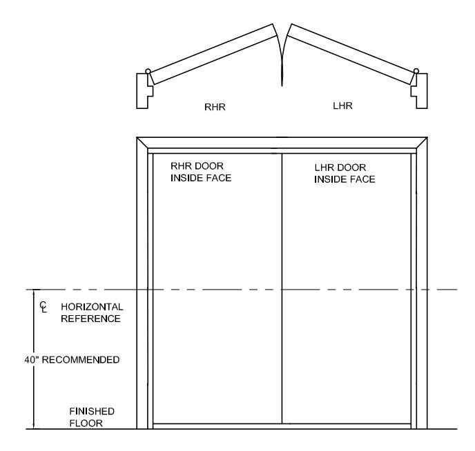
USE TEMPLATES PROVIDED WITH DEVICE
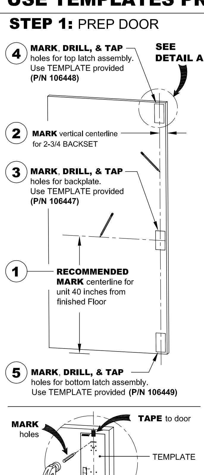
DETAIL A
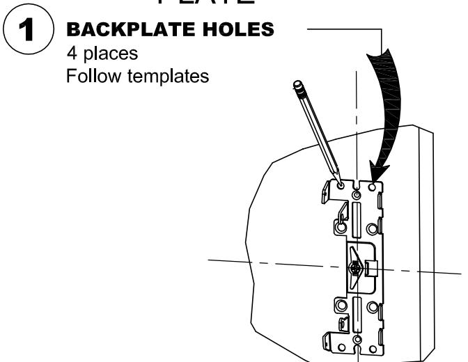
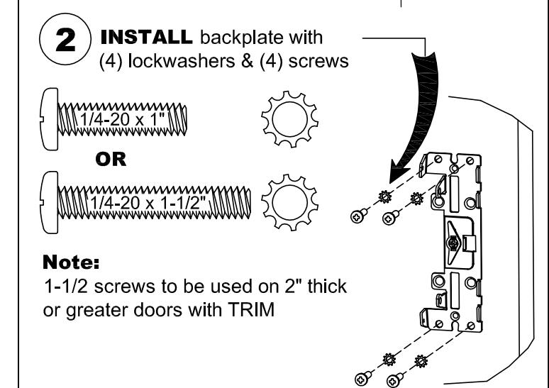
STEP 2: INSTALL MOUNTING PLATE
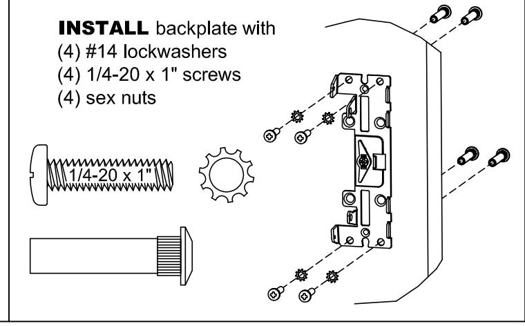
IF SEX NUTS WERE ORDERED
STEP 5: INSTALL DEVICE 1 INSTALL device onto mounting plate with (2) 10-24 x 1/4" screws 10-24 x 1/4"
STEP 6a: INSTALL MORTISE CYLINDER, IF REQUIRED
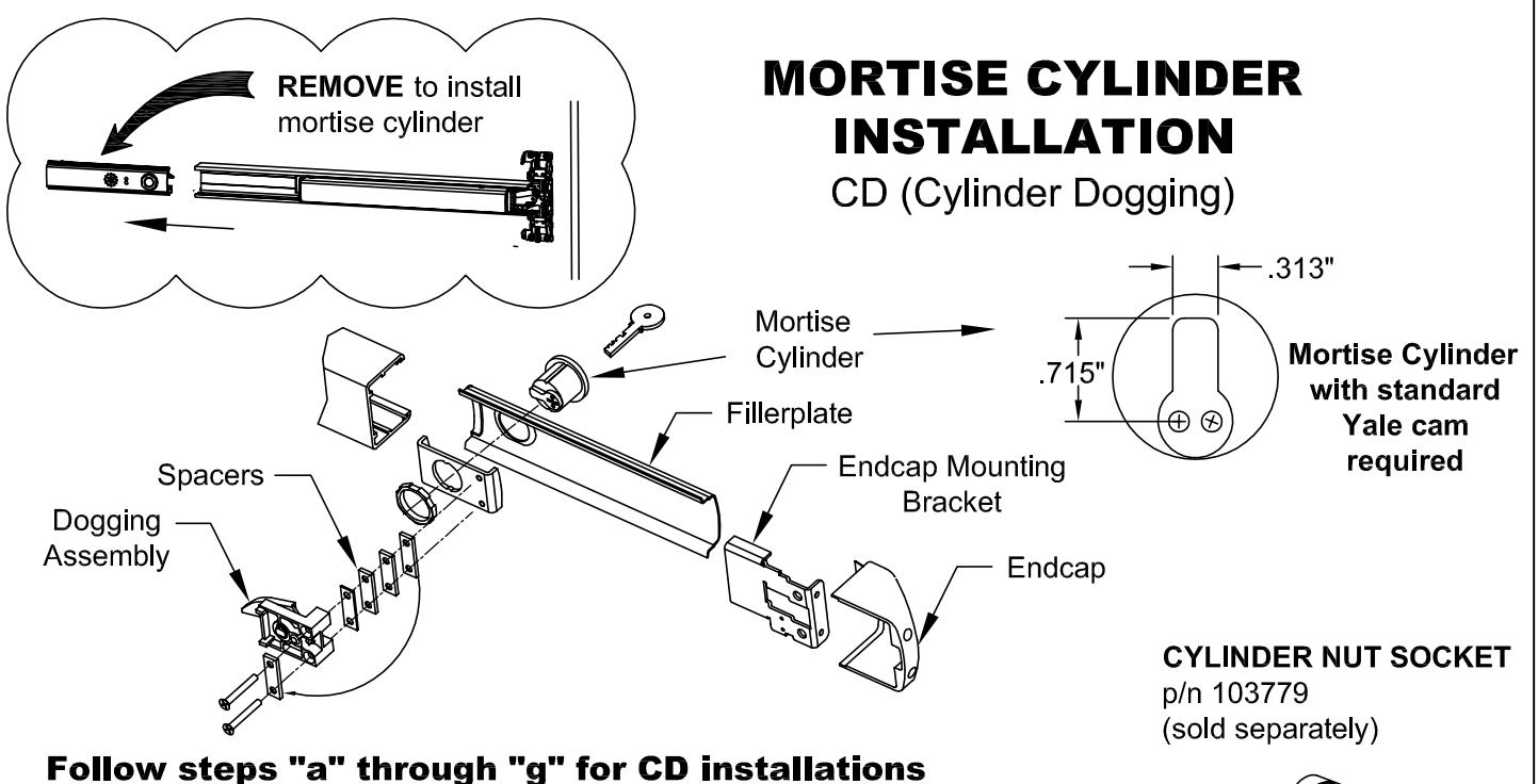
- a. Remove endcap and endcap mounting bracket.
- b. Remove fillerplate.
- c. Remove and discard shipping insert and nut. Loosen (2) screws from dogging assembly.
- d. Install mortise cylinder (sold separately) with large hex nut provided.
- e. Trial fit dogging assembly. If cylinder is too short, remove spacers as necessary and reattach them under the (2) screw heads. Fasten the (2) screws to the rest of the assembly.
NOTE: The key should easily turn in both directions.
- f. Rotate key counterclockwise
- g. Assembly complete. Continue with Panic Hardware instruction.
STEP 6b: CHECKING FOR DEVICE CLEARANCE
(Cut-Off procedure if required)
Slide endcap assembly onto extrusion
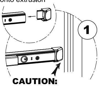
Check for device and door frame clearance. If no cut-off needed, proceed to the next page.
2
Cut fillerplate and extrusion STRAIGHT & SQUARE to desired length and deburr
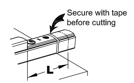
|
Minimum
Fillerplate Length |
||
|---|---|---|
| Туре | Length (L) | |
| LD | 2-1/2" | |
| HD/CD | 3" | |
For aluminum Advantex finish cutdown applications:
After cutting, the baseplate extrusion can be reversed to place the cut end inside the head cover. To do so, loosen the setscrew inside the aluminum baseplate extrusion and slide extrusion out, reverse, & slide back in. Tighten setscrew.
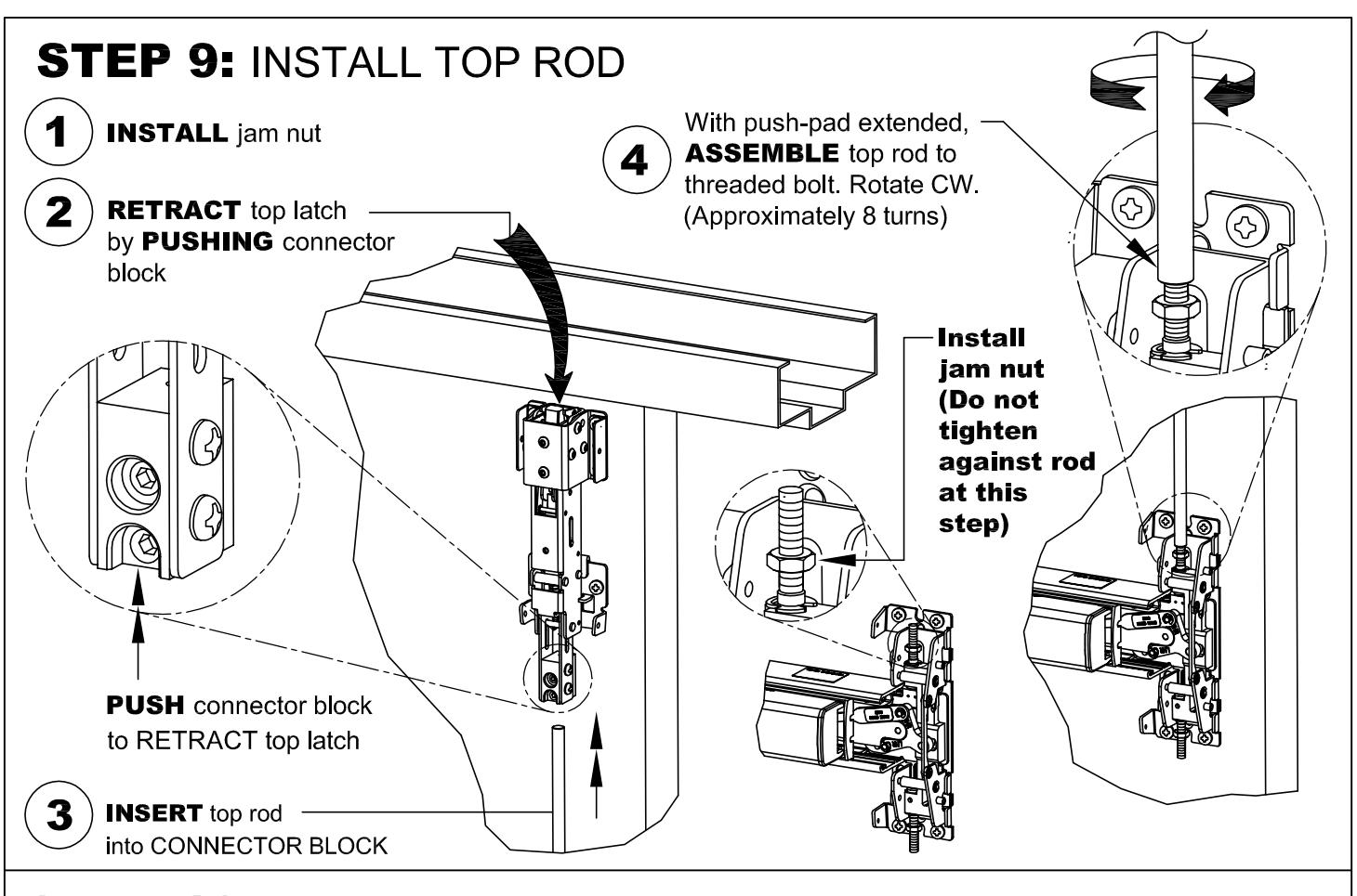
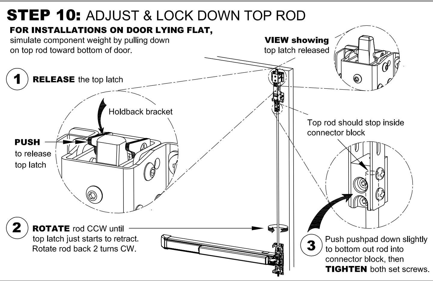
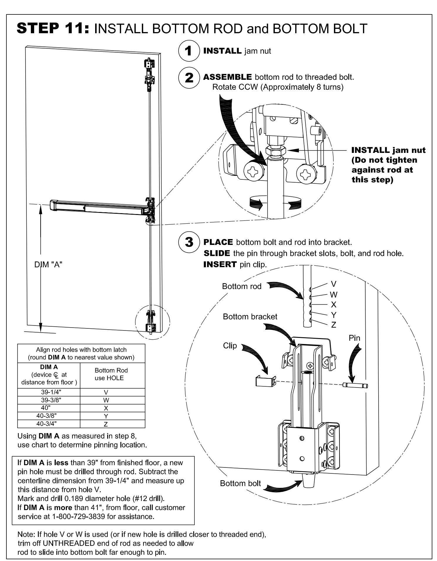
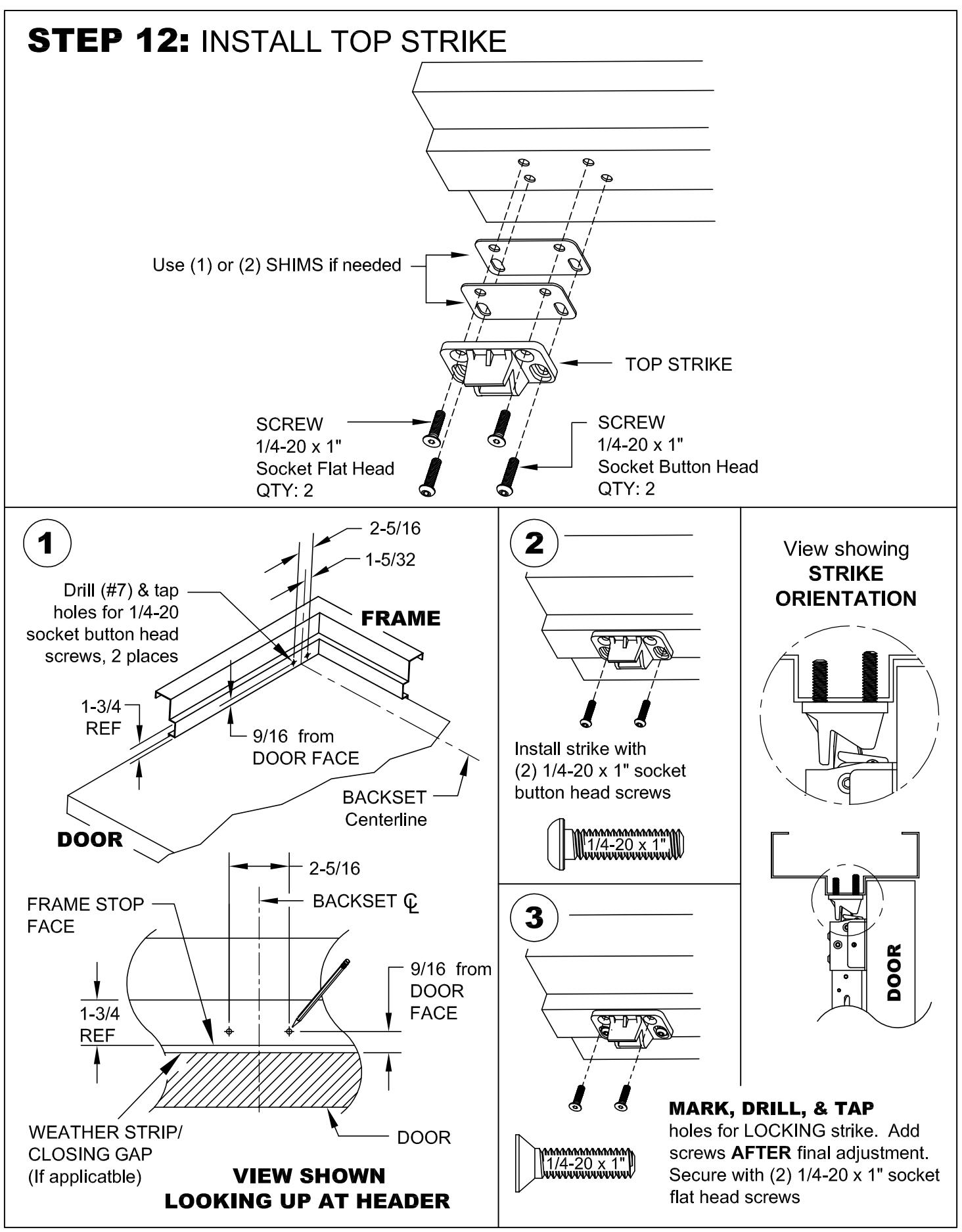
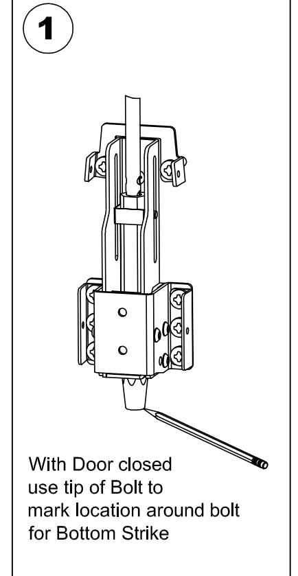
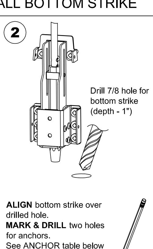
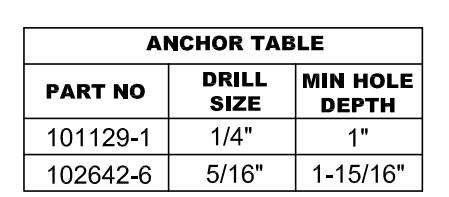
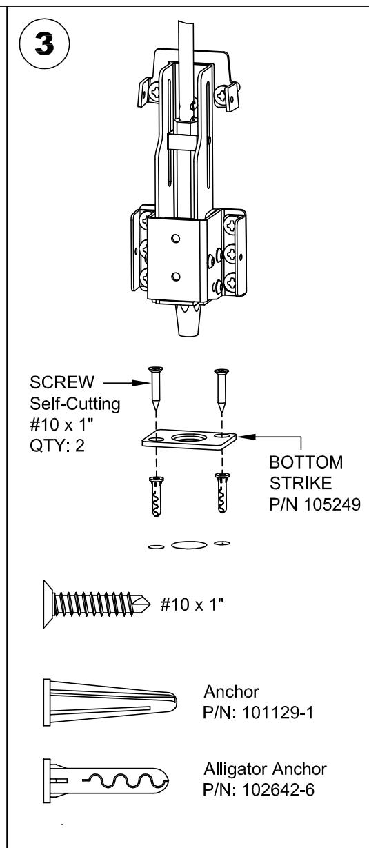
STEP 13: INSTALL BOTTOM STRIKE
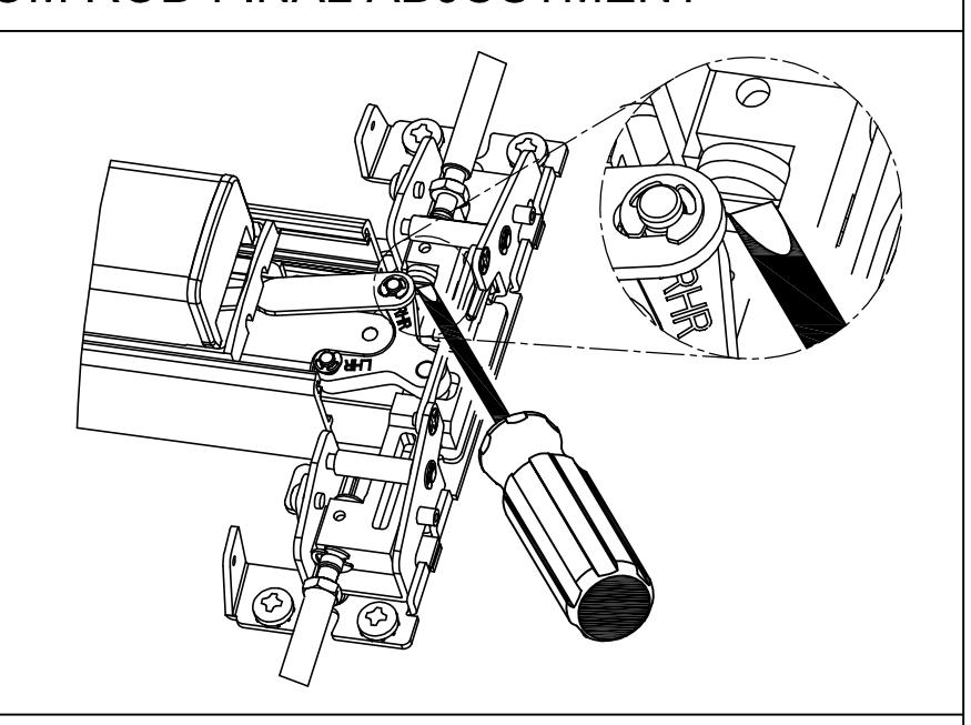
STEP 14: TOP & BOTTOM ROD FINAL ADJUSTMENT
TOP ROD ADJUSTMENT
USE a SLOTTED SCREW DRIVER for turning ROD CONNECTOR
Turn CW to shorten rod length Turn CCW to lengthen rod length

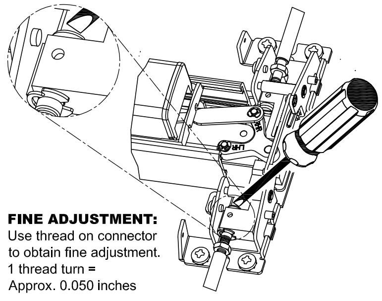
FINE ADJUSTMENT:
Use thread on connector to obtain fine adjustment. 1 thread turn = Approx. 0.050 inches
BOTTOM ROD ADJUSTMENT
USE a SLOTTED SCREW DRIVER for turning ROD CONNECTOR
Turn CW to shorten rod length Turn CCW to lengthen rod length
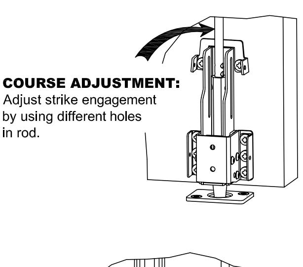
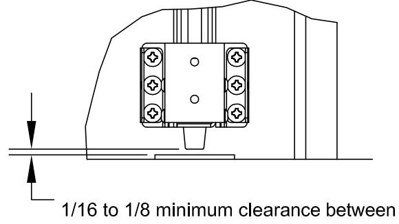
1/16 to 1/8 minimum clearance between bolt and strike with BOLT RETRACTED
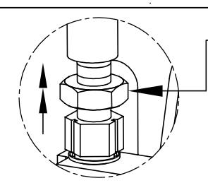
TIGHTEN TOP & BOTTOM JAM NUTS AGAINST RODS AFTER FINAL ADJUSTMENT
Use a 7/16 wrench
TOP LATCH OPERATION
- 1. Close the door. The holdback lever should engage the backside of the strike, allowing the latchbolt to extend. The device should latch securely and latchbolt should fully project into the strike cavity.
- 2. Press the pushpad. The latchbolt should retract fully and smoothly from the strike as the door opens.
- 3. Release the pushpad. The latchbolt should remain retracted until the door is closed.
- 4. Once the latchbolt operation has been evaluated, the strike should be checked and adjusted to allow the door to be held snug to the frame but allow free movement of the latchbolt during normal operation.
When the appropriate position has been set. Two locking holes should be marked, drilled and tapped for a 1/4-20 socket flat head screw (Step 12, part 3). Lock the strike in position with the two screws (See Step 12, part 3).
| DEVICE OPERATION TROUBLESHOOTING | |||
|---|---|---|---|
| SYMPTOM | POSSIBLE CAUSE | SOLUTION | |
| Device not latching | Bottom bolt is not properly aligned with bottom strike hole. | Modify bottom strike hole for fit. | |
| when door closes | Top strike is not installed or not correctly aligned with the top latch. | Install and/or position strike per instructions. | |
| Rods improperly adjusted | Adjust rods per instructions. | ||
| Latches release, but pushpad will not fully depress | Top rod is too long | Shorten top rod | |
| Bottom rod is too short | Lengthen bottom rod | ||
| Latches are not releasing when pushpad is fully depressed | Top rod is too short | Lengthen top rod | |
| Bottom rod is too long | Shorten bottom rod | ||