Alarm Lock DL2500 Installation Instructions
Open the original PDF document
View PDFINSTALLATION INSTRUCTIONS
DL2500-SERIES DIGITAL LOCKS
© Alarm Lock 1995
WI634B 7/95
DESCRIPTION
The Trilogy** DL2500 Series are knob-operated programmable digital locksets designed as direct replacements for standard cylindrical locksets. The DL2500 is available in either a Satin Chrome or Antique Brass finish. It features a heavy-duty ANSI Grade-1 lockset, weather-resistant keypad for exterior use and a sturdy die-cast housing.


Other programmable features include Master, Management, and up to 15 User Codes, making the DL2500 function as a self-contained access-control system.
SPECIFICATIONS
Latchbolt: 1/2" throw brass deadlock bolt reversible for right- and left-hand applications; adjustable front for flat or bevelled doors.
Door Prep: 23/4" backset; 21/8" mounting hole; 1" bore on latch.
Door Thickness: 13/8" to 2", adjustable.
Finish: US26D Satin Chrome or US5 Antique Brass.
Housing: Cast zinc
Dimensions: 71/2"H x 35/32"W
Weight: 5 lb.
Shipping Weight: Approx. 8 lb. Power: Two 9-volt alkaline batteries. Operating Temperature: -20° to +130° F
FEATURES
- Accommodates 13/8" to 2" doors: 23/4" backset. Accepts Schlage 23/8" backset latch for 23/8" backset installations.
- Weather-resistant keypad.
- 3- to 5-digit Master, Management, and Service (1-Time User) Codes.
- Fifteen User Codes.
- More than 29,000,000 possible codes with lockout feature
- Remote override feature.
- Group lockout.
- Key-bypass option.
- Selectable passage option.
- Two 9-volt alakline batteries provide up to 45,000 cycles. An audible low-battery alert will sound before batteries are depleted.
- Fire-rated deadlatch.
- Accepts 3/4" Schlage or Unican deadlatch.
ORDERING INFORMATION
DL2500x26D Knobset, Satin Chrome
DL2500x26DxKO As above, but with Key Override
DL2500x5 Knobset, Antique Brass
DL2500x5xKO As above, but with Key Override
DLRK Remote Release Kit
POWER + Optional Long-Life Battery Pack
INSTALLATION
Step 1. Marking the Door.
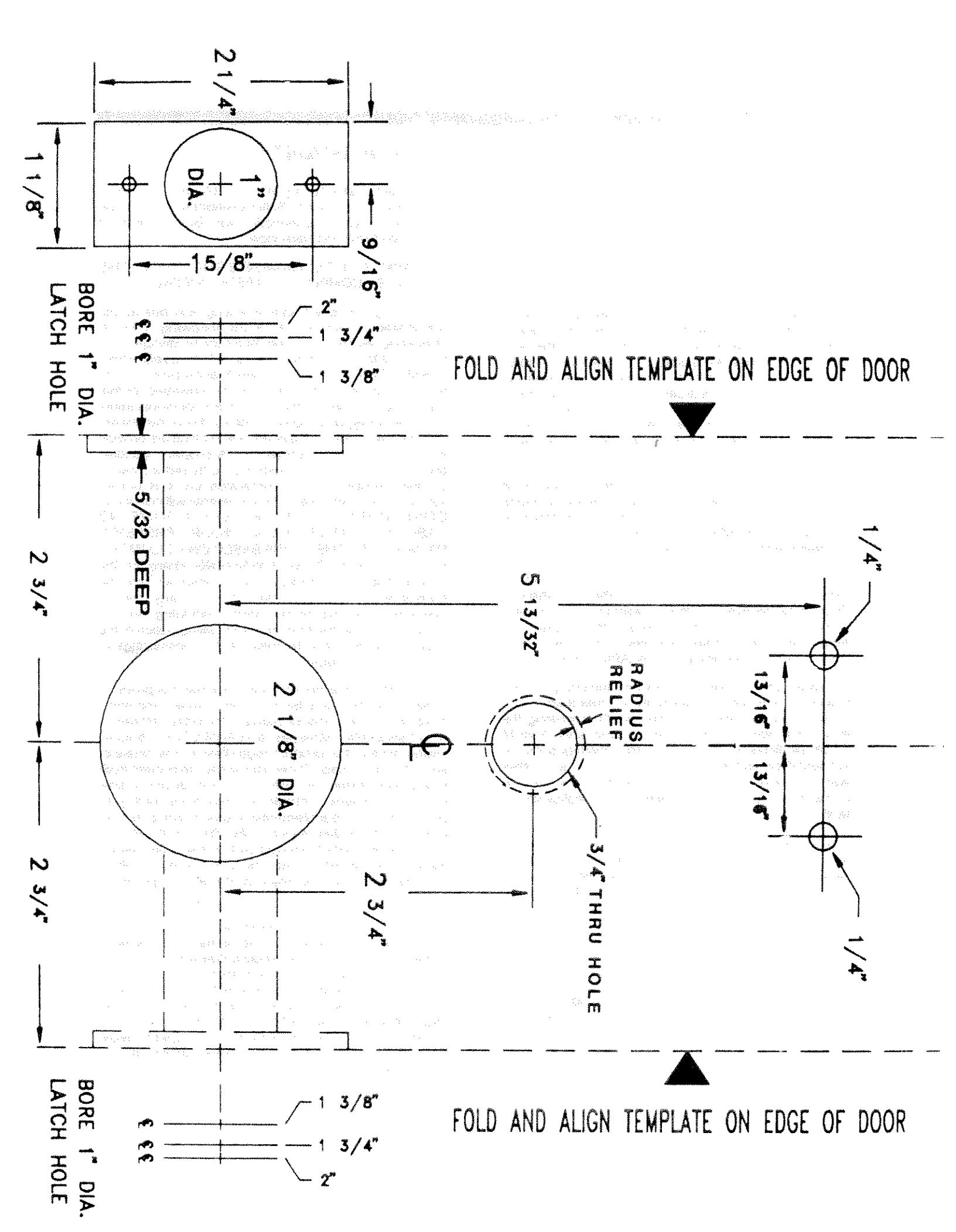
Determine the mounting height from the floor (about 38"). Tear off the template (at the back) and tape it into position on the door. Mark the centers for the following holes:
- (1) 21/8" hole for the lock body.
- (1) 3/4" hole for the keypad cable.
- (2) 1/4" holes for mounting screws.
- (1) 1" hole for the latch.
Note: If the door is predrilled for a standard 23/4" backset, carefully center the 21/3" hole on the template with the existing door hole.
Drill the holes as marked. Mortise out for the latch front. The front should fit flush with the door edge. If the unit is being installed with remote release, refer to the instructions for the remote release package.
Step 2. Adjusting for Door Thickness.
Measure the door thickness. The DL2500 is factory set for a 134" thick door. If adjustment is needed, remove the six screws shown in Fig. 1, then remove the Exterior Keypad Housing. Screw the Nut in or out until the distance between the centerline of the Retractor and the Exterior Mounting Plate is half the door thickness. See Table 1 and Fig. 1. Note: Be sure that the Mounting Plate is pressed firmly against the Nut.
| DOOR THICKNESS | SET FOR |
|---|---|
| 2" | 1,5 |
| 13/4" | 7/8" |
| 13/8" | ¹ 1⁄16" |
Table 1
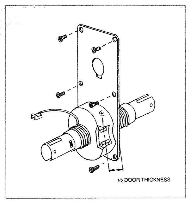
Fig. 1
Step 3. Installing the Latch.
With the Latch out of the door, slide the Exterior Keypad Housing with the Lock Body into the prepared holes. Be sure that the keypad and the motor wires pass clearly through their respective holes and the Retractor is centered in the latch hole when viewed edge on (see Fig. 2). (If adjustment is necessary, refer back to Step 2.) After checking Retractor
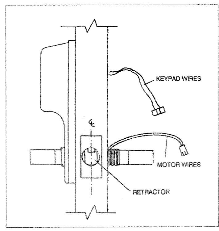
Fig. 2
position, slide out the Lock Housing until it clears the latch cutout. Referring to Fig. 3, insert the Latch and slide the Lock
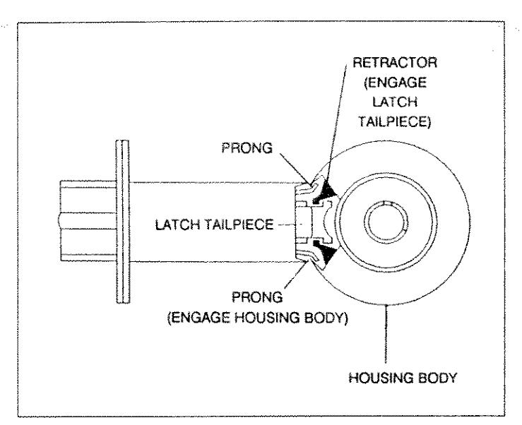
Fig. 3
Housing back in, making sure that (a) the Latch Prongs engage the Housing Body and (b) the Latch Tailpiece engages the Retractor. (If necessary, reinsert wires through the mounting holes.) Install Latch screws.
Step 4. Installing the Interior Mounting Plate.
Slide the Interior Mounting Plate over the Inside Hub (Fig. 4). Secure the plate to the door with the Nut and tighten using the supplied spanner wrench. Tighten the #6-32 hexagon socket set screw using the Allen wrench supplied. Check for proper alignment with mounting holes before tightening fully. Using the Interior Mounting Plate as a template, drill two 1/8" diameter holes at the bottom, then install two 1/8" self-tapping screws.
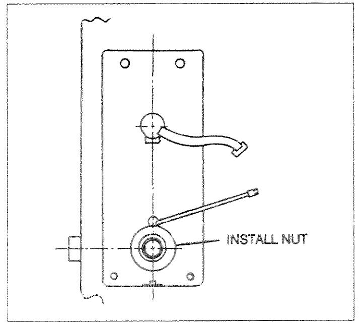
Fig. 4
Step 5. Installing the Interior Housing.
Before the Interior Housing can be installed, connect the keypad and motor wires to the printed circuit board. See Fig. 5 for locations. Connectors are keyed to assure proper
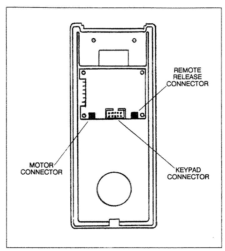
Fig. 5
alignment. Once connected, place the Interior Housing over the mounting plate, making sure that the wires are not caught between plate and housing. Two #8-32x21/4" screws (supplied) secure the Interior Housing to the Exterior Plate (Fig. 6); these may have to be shortened in accordance with Table
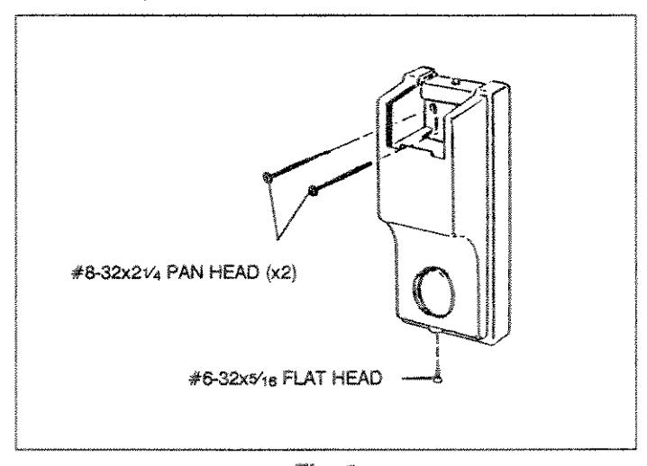
Fig. 6
2. Then, install them into the two holes in the battery compartment, through the Interior Mounting Plate and into the Exterior Mounting Plate and tighten. Also install one #6-32x5/16" screw at the bottom of the Interior Housing.
| DOOR SIZE | SCREW LENGTH |
|---|---|
| 2" | 21/4" |
| 13/4" | 2" |
| 13/8 | 15/8" |
Table 2.
Step 6. Installing the Knobs.
Slide the Interior Knob (see Fig. 7) onto the spindle. Depress the Knob Catch and push the Knob into position. Pull on the Knob to check for proper engagement with the Catch. Check the lock for proper operation at this time. The Knob should operate freely. If the lock binds or sticks, it should be corrected before proceeding.
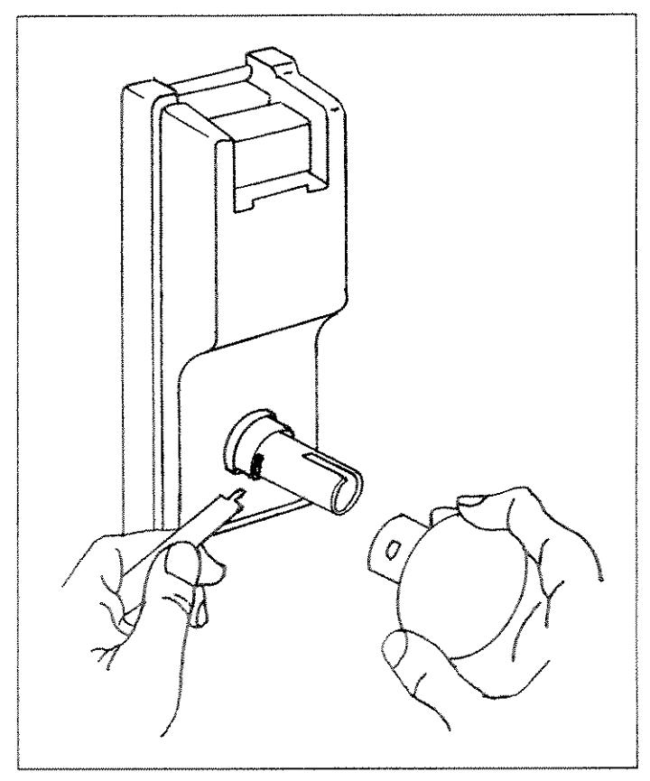
Fig. 7
The Exterior Knob is factory assembled with the Key Cylinder and can be used on left- or right-handed doors. Line up the keyway in the Knob with the slots in the Spindle, then turn the key clockwise as far as it will go. At the same time, depress the Knob Catch and push the Knob straight in until the Knob Catch clicks into place. Turn the key to its vertical position and remove it.
Important: Use of a cylinder tailpiece longer than that supplied may damage tha lock drive motor.
Step 7. Installing the Batteries.
Check that the two housings are straight and that all hardware is tight. Then, install the two 9-volt batteries (supplied) into the battery compartment. When batteries are installed, a startup beep will sound at the keypad, indicating that the lock is functional.
Now test the factory-programmed Master Code. Press [1] [2] [3] [4] [5]. The keypad should beep with each keypress, and again after the last digit is entered, indicating acceptance of a valid code. Check that the lock unlocks, the knob operates smoothly, and the lock relocks within 5 seconds. If the factory code operates properly, install the battery cover and secure with either the #4-40 flat-head Phillips or oval-head tamper-proof screw.
Step 8. Installing the Strike.
Mark the location of the Strike on the door frame, making sure to align the Strike with the Latch. Mortise the frame and install the Strike and dust box with the two screws supplied (Fig. 8).
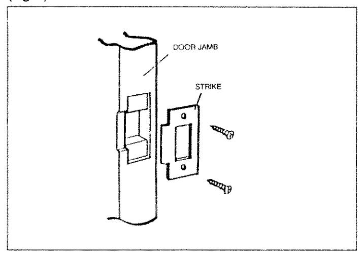
Fig. 8
This completes the installation. Recheck the lock using the factory-programmed Master Code (1-2-3-4-5). If the lock is functioning properly, reprogram the Master Code and program other required codes, referring to the User's Guide (Ol171) for programming instructions.
REMOTE RELEASE
To remotely unlock the door, wire the 2-pin connector with leads (supplied) to an external normally-open momentary-contact pushbutton switch. Splice 2-conductor cable onto the existing leads and route the cable within the door and adjacent walls to the switch. (Do not surface-mount the wiring.) Plug the 2-pin connector into the mating REMOTE RELEASE connector on the circuit board. A momentary closure of the switch will then unlock the door. Note: The DLRK Remote Release Kit includes a switch and an ample supply of 2-conductor cable.
LUBRICATION
The Flex-Drive™ locking mechanism is factory lubricated using a synthetic spray lubricant and should require no further attention. However, if lubrication is obviously required, use a low-viscosity spray lubricant (Super Lube® or equivalent). Do not use grease or graphite!
ALARM LOCK LIMITED WARRANTY
ALARM LOCK Systems, Inc. (ALARM LOCK) warrants its products to be free from manufacturing defects in materials and workmanship for two years following the date of manufacture. ALARM LOCK will, within said period, at its option, repair or replace any product failing to operate, without charge to the original purchaser or user.
In case of defect, contact the security professional who installed and maintains your security system. ALARM LOCK shall have no obligation under this warranty, or otherwise, if the product has been repaired by others, improperly installed, improperly used, abused, altered, damaged, subjected to accident, nuisance, flood, fire or acts of God, or on which any serial numbers have been altered, defaced or removed. ALARM LOCK will not be responsible for any dismantling, reassembly or reinstallation charges.
In order to exercise the warranty, the product must be returned by the user or purchaser, shipping costs prepaid and insured to ALARM LOCK. After repair or replacement, ALARM LOCK assumes the cost of returning products under warranty.
There are no warranties, express or implied, which extend beyond the description on the face thereof. There is no express or implied warranty of merchantability or a warranty of fitness for a particular purpose. Additionally, this warranty is in lieu of all other obligations or liabilities on the part of ALARM LOCK.
Any action for breach of warranty, including but not limited to any implied warranty or merchantability, must be brought within the six months following the end of the warranty period. In no case shall ALARM LOCK be liable to anyone for any consequential or incidental damages for breach of this or any other warranty, express or implied, even if the loss or damage is caused by the seller's own negligence or fault.
This warranty contains the entire warranty. It is the sole warranty and any prior agreements or representations, whether oral or written, are either merged herein or are expressly cancelled. ALARM LOCK neither assumes, nor authorizes any other person purporting to act on its behalf to modify, to change, or to assume for it, any other warranty or liability concerning its products.
In no event shall ALARM LOCK be liable for an amount in excess of ALARM LOCK's original selling price of the product, for the loss or damage, whether direct, indirect, incidental, consequential, or otherwise arising out of any failure of the product. Seller's warranty, as hereinabove set forth, shall not be enlarged, diminished or affected by, and no
obligation or liability shall arise or grow out of, Seller's rendering of technical advice or service in connection with Buyer's order of the goods furnished hereunder.
ALARM LOCK RECOMMENDS THAT THE ENTIRE SYSTEM BE COM-PLETELY TESTED WEEKLY.
Warning: Despite frequent testing, and due to, but not limited to, any or all of the following: criminal tampering, electrical or communications disruption, it is possible for the system to fail to perform as expected. ALARM LOCK does not represent that the product/system may not be compromised or circumvented; or that the product or system will prevent any personal injury or property loss by burglary, robbery, fire or otherwise; nor that the product or system will in all cases provide adequate warning or protection. A properly installed and maintained alarm or lock may only reduce risk of burglary, robbery, fire or otherwise but it is not insurance or a guarantee that these events will not occur. CONSEQUENTLY, SELLER SHALL HAVE NO LIABILITY FOR ANY PER-SONAL INJURY, PROPERTY DAMAGE, OR OTHER LOSS BASED ON A CLAIM THE PRODUCT FAILED TO GIVE WARNING. Therefore, the installer should in turn advise the consumer, and the consumer is hereby advised, to take any and all precautions for his or her safety including but not limited to, fleeing the premises and calling police or fire department, in order to mitigate the possibilities of harm and/or damage.
ALARM LOCK is not an insurer of either the property or safety of the user's family or employees, and limits its liability for any loss or damage including incidental or consequential damages to ALARM LOCK's original selling price of the product regardless of the cause of such loss or damage. If the user wishes to protect itself to a greater extent, ALARM LOCK will, at user's sole cost and expense, obtain an insurance policy to protect the user, supplemental to user's own policy, at a premium to be determined by ALARM LOCK's insurer upon written notice from user by Certified Mail, Return Receipt Requested, to ALARM LOCK's home office address, and upon payment of the annual premium cost by user.
This warranty shall be construed according to the laws of the State of New York. Some states do not allow limitations on how long an implied Warranty lasts or do not allow the exclusion or limitation of incidential or consequential damages, or differentiate in their treatment of limitations of liability for ordinary or gross negligence, so the above limitations or exclusions may not apply to you. This Warranty gives you specific legal rights and you may also have other rights which vary from state to state.
Alarm Lock Systems, Inc., 345 Bayview Avenue, Amityville, New York 11701 Call Toll Free: 800-ALA-LOCK (800-252-5625) • FAX: (516) 789-3383