Corbin Russwin UT5200 Series Parts Service Manual
Open the original PDF document
View PDF

UT5200 Series
Pre-Assembled Unit Locks Parts and Service Manual
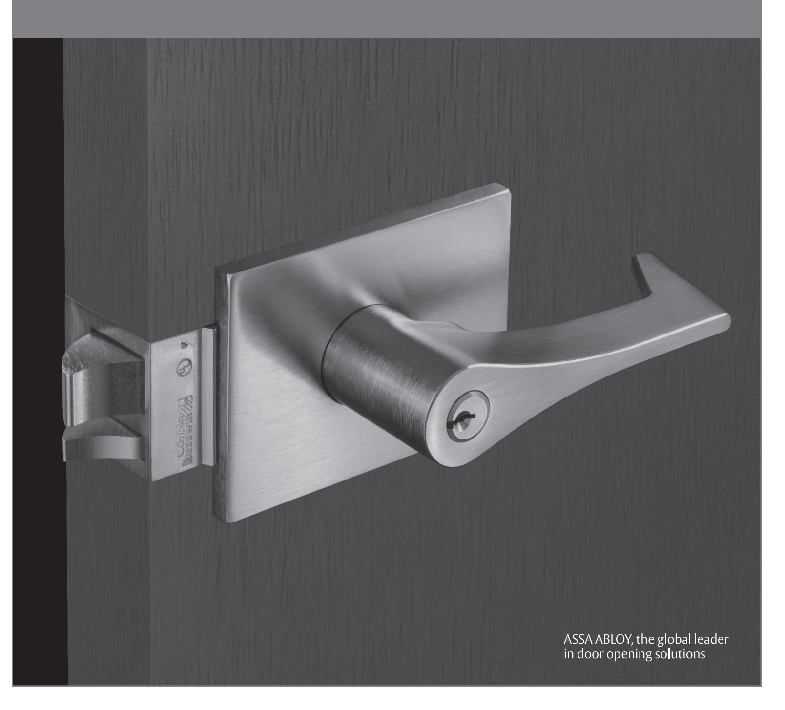
- Refer to the installation instructions for complete installation.
- In order to simplify the ordering procedure, parts are only available as listed.
- To order parts, use the appropriate Part Number and specify Finish ( fin ) as directed. For example, to order ten Knob Sleeves for the UT5255 Function in 626 finish, use the following configurations:
| Quantity | Part Number | Finish | Hand |
|---|---|---|---|
| 10 | 401F08 | 626 |
• For assistance, contact your authorized Corbin Russwin Distributor or contact Corbin Russwin directly at the address on the back cover.
The warranty on Corbin Russwin products becomes void if the product is modified in any way, regardless of whether the modifications causes or contributes to any alleged defect. If a Corbin Russwin product is modified it may no longer meet industry certification and quality control standards applicable to the original product and is no longer a genuine Corbin Russwin product.

| Introduction 2 | ||
|---|---|---|
| Quick Conversion 4 | ||
| Do You have the current model? 5 | ||
| Parts List | ||
| UT5210 | Passage or Closet 6-7 | |
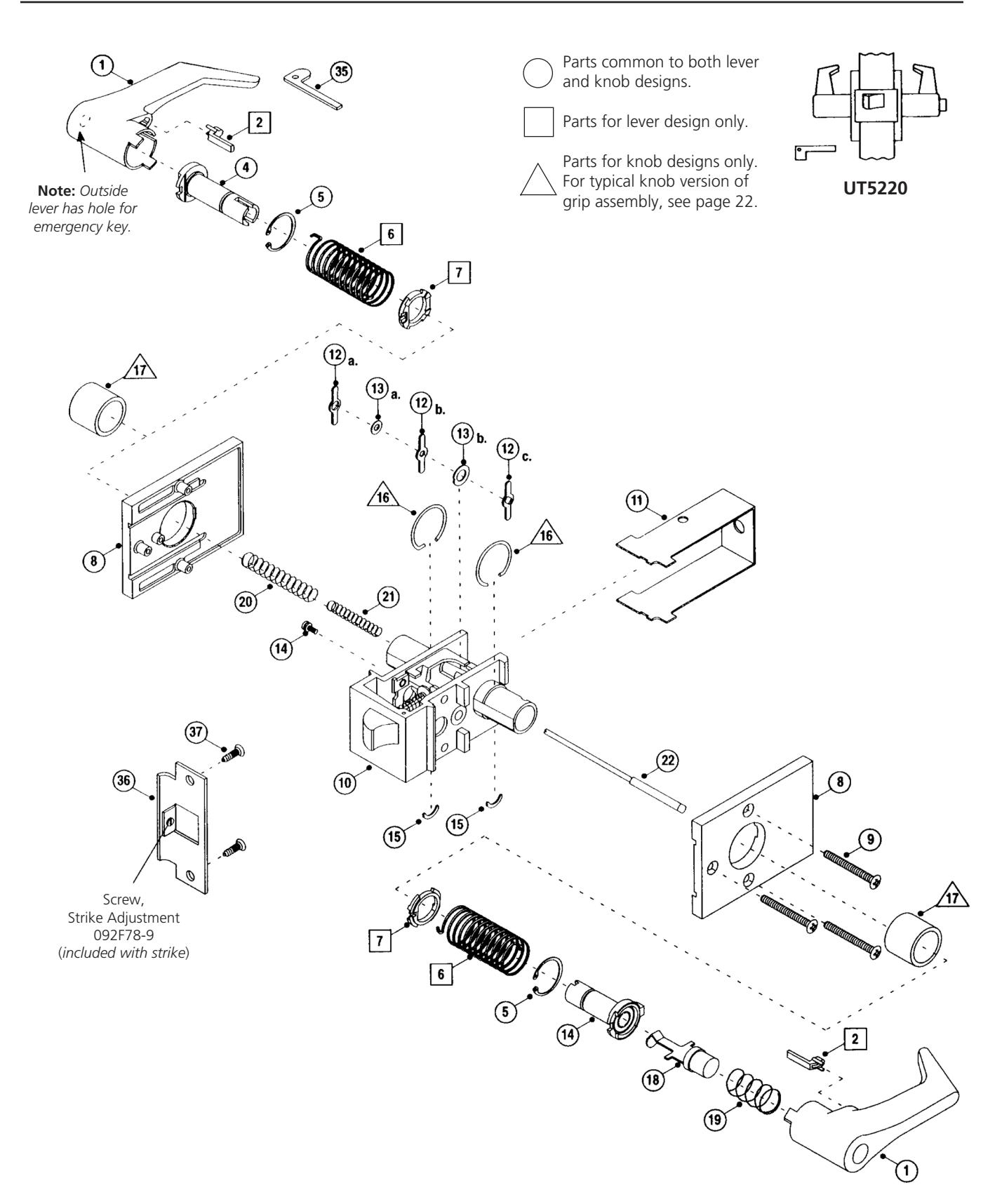
| UT5220 | Privacy, Bedroom or Bathroom 8-9 | |
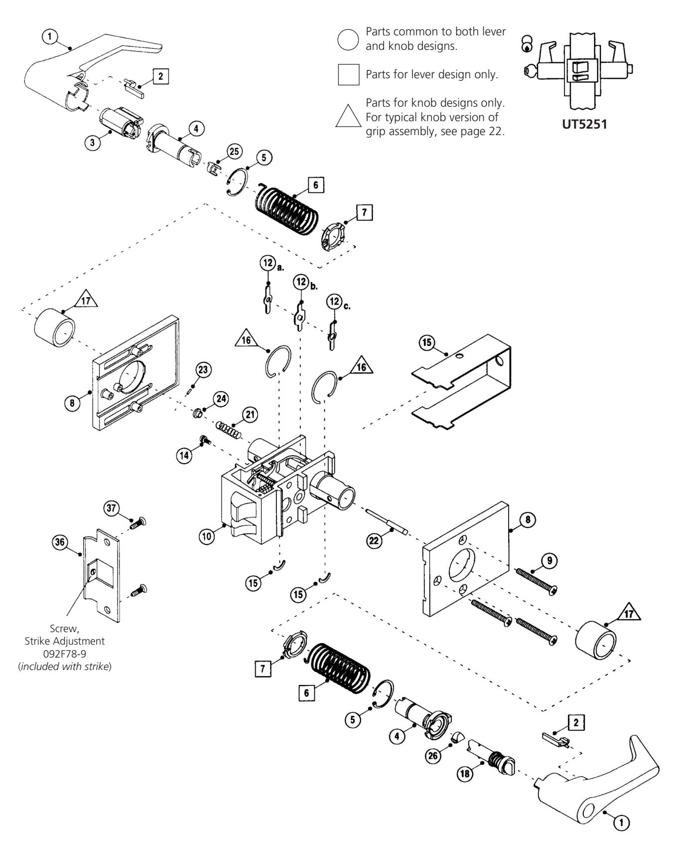
| UT5251 | Entrance or Office 10-11 | |
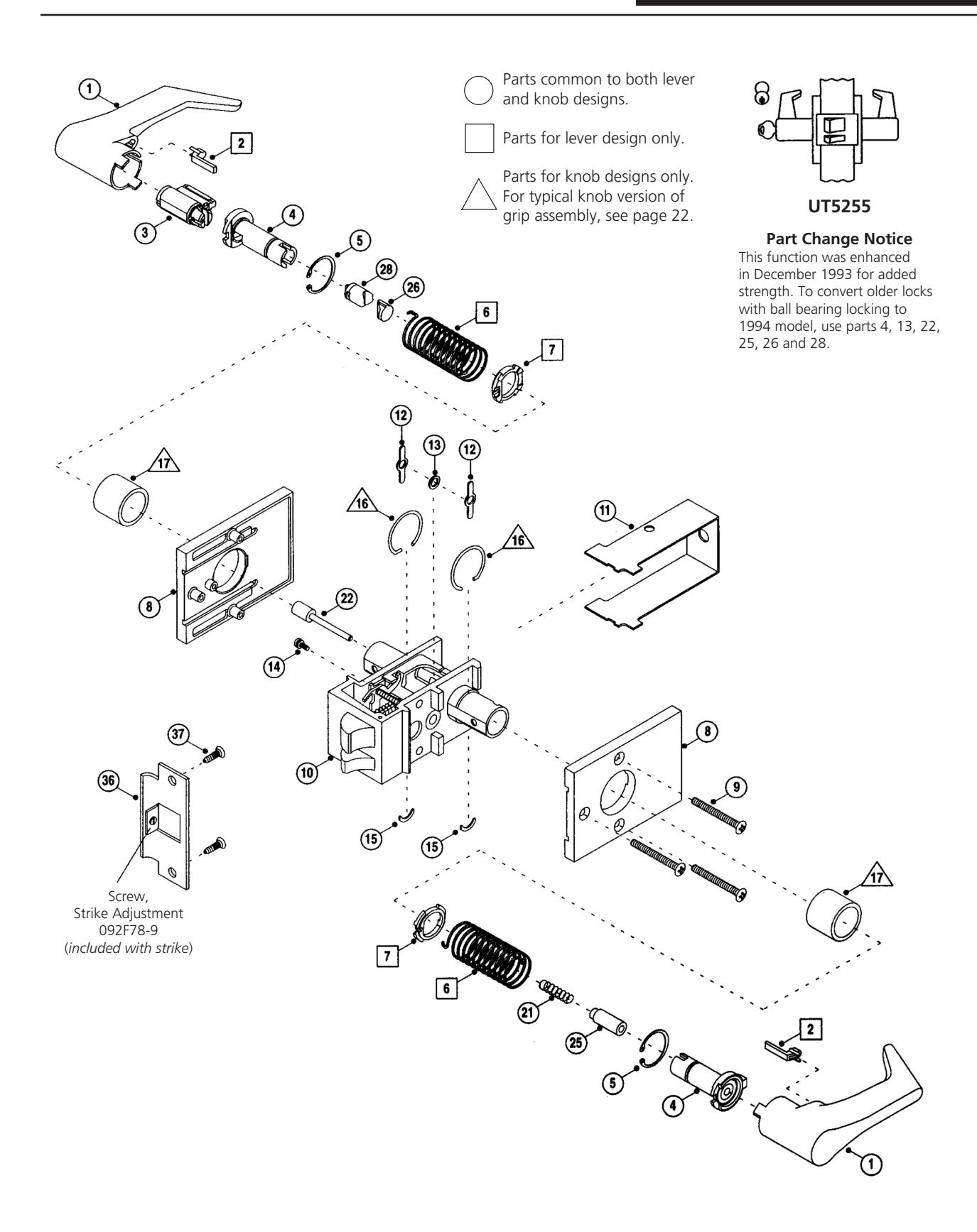
| UT5255 | Classroom 12-13 | |
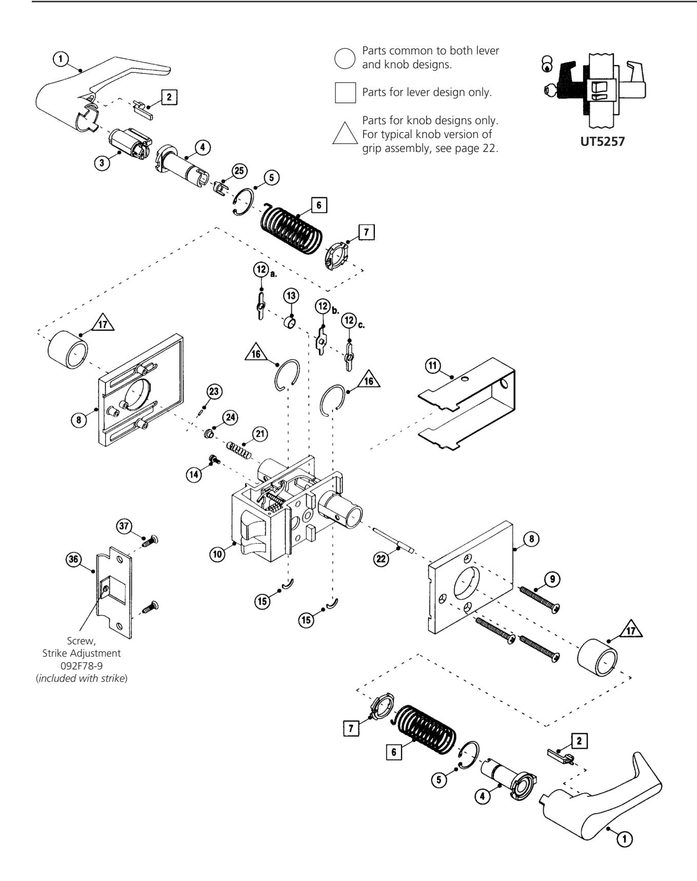
| UT5257 | Storeroom or Closet 14-15 | |
| UT5261 | Entrance or Office (levers only) 16-17 | |
| UT5272 | Apartment, Exit or Public Toilet 18-19 | |
| UT5282 | Store Door 20-21 | |
| Typical Knob Configuration 22 | ||
| Interchangeable Core Configuration 23 | ||
| Lever and Knob Shank – Comparison Guide 24 | ||
| Options and Accessories 25 | ||
| Parts Cross Reference 26-28 | ||
| Routine Maintenance 29 | ||
| Troubleshooting Guide 30-31 | ||
| Cylinder Removal Instructions 32 | ||
| Current Model | ||
| Lever Version 32-33 | ||
| Knob Version 34-35 | ||
| Discontinued Models | ||
| Corbin 2000/2200/2400 and 500 Series (1899 - 1963) 36 | ||
| Corbin 700/Russwin 1600 Series "Baby" Unit Lock 37 | ||
| Russwin 2100/2800 Series only (1904 - 1968) 38 | ||
| Service Procedures 39-40 | ||
| Changing from Knobs to Levers 39 | ||
| Changing Hand of Lockset: | ||
| Knob Version 39-40 | ||
| Lever Version 41 |

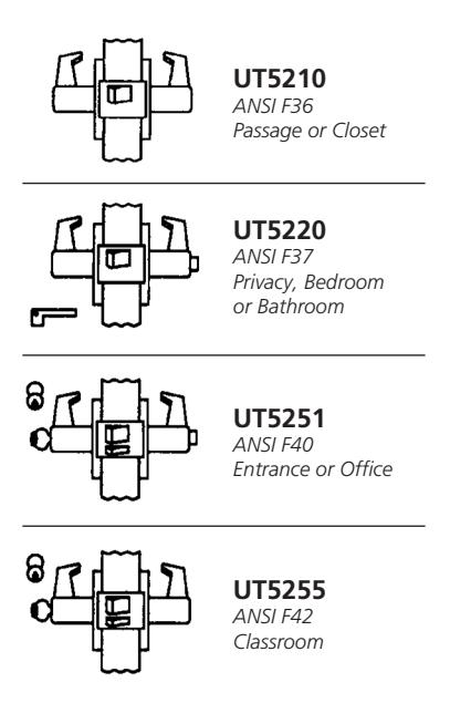
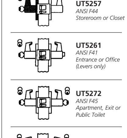
Quick Conversion As of May 1993, Corbin Russwin has introduced a new simplified product numbering system that makes it easy to identify, specify and order a complete line of architectural hardware.
Although the catalog numbers have changed, the part numbers have remained the same. Identifying parts is as easy as it's always been! To find a function or trim design, simply use this "Quick Conversion" as a helpful cross reference bridge from the former Corbin and Russwin languages (pre-May 1993) to the new Corbin Russwin language.
Corbin
|
Function No.
Before 5/93 |
Function No.
After 5/93 |
|
|---|---|---|
| 310 | UT5210 | 6 |
| 320 | UT5220 | 8 |
| 351 | UT5251 | 10 |
| 354 | UT5272 | 18 |
| 355 | UT5255 | 12 |
| 357 | UT5257 | 14 |
| 361 | UT5261 | 16 |
| 388 | UT5282 | 20 |
|
Trim Design
Before 5/93 |
Trim Design
After 5/93 |
|---|---|
| 912R | ESE |
| 964 Global | GRE |
| 966 Pierce | BRE |
Russwin
|
Function No.
Before 5/93 |
Function No.
After 5/93 |
Page |
|---|---|---|
| 510 | UT5210 | 6 |
| 520 | UT5220 | 8 |
| 540 | UT5251 | 10 |
|
540 5/
8 |
UT5255 | 12 |
| 546 | UT5261 | 16 |
|
546 1/
2 |
UT5272 | 18 |
|
548 1/
2 |
UT5282 | 20 |
| 552 | UT5257 | 14 |
|
Trim Design
Before 5/93 |
Trim Design
After 5/93 |
|---|---|
| 912R | ESE |
| Ashford | GRE |
| Belmont | BRE |
Function
The warranty on Corbin Russwin products becomes void if the product is modified in any way, regardless of whether the modifications causes or contributes to any alleged defect. If a Corbin Russwin product is modified it may no longer meet industry certification and quality control standards applicable to the original product and is no longer a genuine Corbin Russwin product.
Copyright © 1999-2018, ASSA ABLOY Access and Egress Hardware Group, Inc. All rights reserved. Reproduction in whole or in part without the express written permission of ASSA ABLOY Access and Egress Hardware Group, Inc. is prohibited. Patent pending and/or patent www.assaabloydss.com/patents.

UT5282 ANSI F46 Store Door
Historically, no lockset design has been as closely associated with the Corbin Russwin brand name as the unit lock. The unit lock's sturdy, rugged construction gives it an unrivaled lifetime of smooth, trouble-free operation. Tens of thousands of these locks have already outlasted the buildings they were installed in! Now, past its 100th anniversary, the unit lock has evolved through several different models.
The rectangular chassis unit lock was invented by Byron Phelps, former mayor of Seattle, Washington. He brought his invention across the country in 1898 to P.F. Corbin, who licensed and manufactured it. The first patents were issued on January 31 and June 6, 1899. Today's UT5200 Series locksets are closely based on that design.
Instead of the large rectangular chassis by Corbin, the earliest Russwin unit lock had a different design and door prep. A 1" round knob spindle was completely separated from a small rectangular case around the latch area. This design was invented by Henry Voight, an extremely prolific lock inventor of that era, then employed by Russell & Erwin Mfg. Co. Its first patents issued on April 19 and August 30, 1904.
The exploded views in this manual are limited to the current model of UT5200 Series parts. For most functions, this includes all locks manufactured since 1968, although certain current parts will operate in some older models. Since locksmiths are often called on to rekey older locksets, we include cylinder removal instructions for earlier models
later in this manual. Use the table below to help identify the various models.
In reviewing the table, keep in mind that Corbin Russwin began as separate companies, so there is not a Corbin-to-Russwin cross-reference for the early models.
Old catalogs, price books and engineering drawings, as well as physical samples were studied to compile the table. However, a few pieces of the puzzle were still missing at press time.
Anyone with locksets or positive documentation to correct or add to this information is invited to contact the Corbin Russwin Marketing Department.
With lock removed, apply these clues to the table below to determine the model of your lock.
- If it bears the Russwin name and the knobs have a round shaft separate from a small rectangular chassis, it is the Russwin 2100/2800 Series.
- Look for numbers cast into underside of escutcheons.
- Observe keyway orientation and measure chassis dimensions.
- Read latest patent date stamped into chassis cover.
- Look for numbers stamped into top or bottom edge of chassis frame (Note: some numbers are not significant)
|
Corbin
Series |
Russwin
Series |
Keyway |
Chassis
Dimensions |
Backset |
Cylinder
Series |
First
Sold |
Last
Sold |
Remarks |
|---|---|---|---|---|---|---|---|---|
| (0)2000* | vertical |
1 1/2 x 3 1/2"
1 1/2 x 3 3/4" 1 1/2 x 3 1/2" |
2 3/4"
3" 3" |
250 | 1899 | 1913 | 4 or 5 pin 99 or 97 keyway | |
| (0)2200* | vertical |
2 x 3 3/4"
2 3/16 x 4" 2 5/8 x 4" |
3"
3" |
250 | 1913 | 1953 | anti-friction fire (dead) latch | |
| (0)2400* | vertical |
2 x 3 1/2"
2 x 3 3/4" 2 5/8 x 3 3/4" |
2 3/4"
3" 3" |
250 | 1913 | 1953 | ||
| 2100/2800 | vertical | (see remarks) | 3" | 2100 | 1904 | 1968 | small chassis + 1" spindle | |
| 7xx-500 | vertical | 2 5/8 x 3 3/4" | 3" | 250 | 1954 | 1966 | = largest 2400 Series renamed | |
| ? | vertical | 1 3/8 x 3" | 2 3/8" | ? | ? | ? | small model | |
| 9xx-700 | 1600 | horizontal | 1 3/4 x 3 1/4" | 2 1/2" | 260 & 250 | 1949 | 1954 | small model |
| 9xx-900 | 600 | horizontal | 1 3/4 x 3 1/4" | 2 1/2" | 460 | 1955 | 1963 | |
| 9xx-300 | 500 | horizontal | 1 3/4 x 3 5/8" | 2 1/2" | 460 | 1963 | current | changed in 1968; now UT5200 |
* & quot;0" prefix designates deadlatching. Numbers without this prefix are not deadlatching.
The warranty on Corbin Russwin products becomes void if the product is modified in any way, regardless of whether the modifications causes or contributes to any alleged defect. If a Corbin Russwin product is modified it may no longer meet industry certification and quality control standards applicable to the original product and is no longer a genuine Corbin Russwin product.

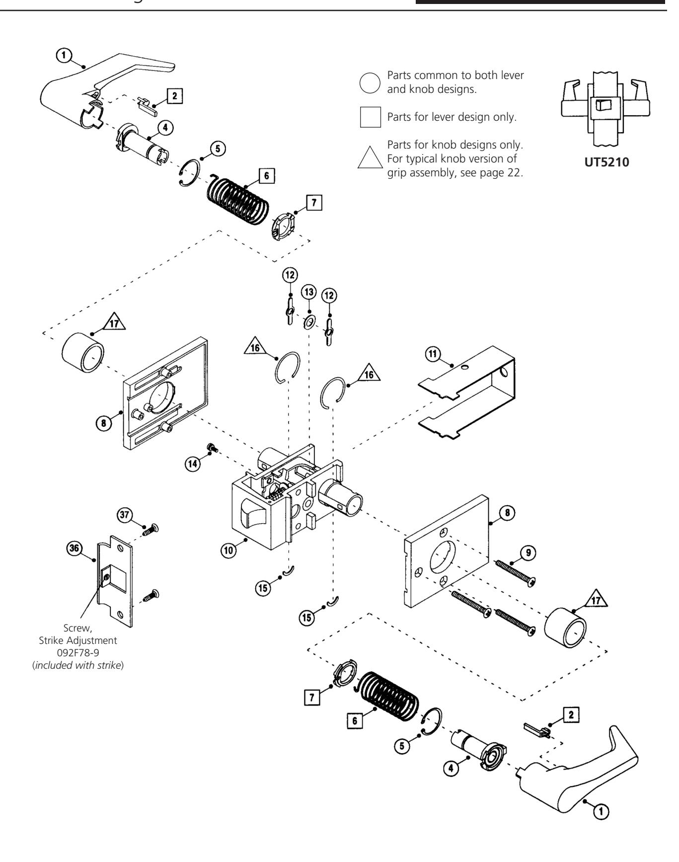
| ITEM | PART NO. | SPECIFY | DESCRIPTION |
|---|---|---|---|
| 1 |
(see chart
below) |
Lever or Knob:
plain both sides |
|
| 2 | 613F02-9 | Lever Insert (gray) | |
| 4 |
102F198
060F91-8 |
Lever Shank
Knob Shank |
|
| 5 |
242F50-8
219F80-8 |
Shank Retainer for
Lever Knob |
|
| 6 |
103F44-8
103F45-8 |
Return Spring
Clockwise (RH) Lever Counter Clockwise (LH) Lever |
|
| 7 | 171F79-8 | Return Spring Anchor | |
| 8 |
144F33
144F34 301F56-7 605F90 415F15 415F16 415F27-7 605F91 |
fin
fin |
Escutcheon (lever Trim)
inside outside outside, extended lip inside, lead lined option M28 Escutcheon (knob Trim) inside outside outside, extended lip inside, lead lined option M28 |
| ITEM | PART NO. | SPECIFY | DESCRIPTION |
|---|---|---|---|
| 9 | 222F85 | fin | Mounting Screw |
| 10 | 496F33 | fin | Chassis |
| 11 | 138F88-8 | Chassis Cover | |
| 12 | 060F42-8 | Hub | |
| 13 | 060F33-8 | Hub Spacer | |
| 14 | 249F76-8 | Screw, fixed escutcheon | |
| 15 | 078F07-8 | Grip Retainer | |
| 16 | 078F08-8 | Grip Retainer Ring | |
| 17 | 401F08 | fin | Sleeve |
| 36 | 236L75M020 | fin |
ANSI Strike
(see page 25 for options) |
| 37 | 480F70 | fin | Screw Packet for Strike |
Lever ( specify finish )
Note: Levers are handed.
RH lever: Clockwise rotation. For outside of RH or RHR locks and inside of LH or LHR locks.
LH lever: Counter-clockwise rotation. For outside of LH or LHR locks and inside of RH or RHR locks.
| Regular | Tactile Warning | |||
|---|---|---|---|---|
|
Essex (RH)
Essex (LH) |
Essex (RH) | Essex (LH) | ||
| plain | 613F10-2 | 613F11-2 | 613F14-2 | 613F15-2 |
Knobs ( specify finish )
| Regular | Tactile Warning | |||
|---|---|---|---|---|
|
Global
Belmont |
Global | Belmont | ||
| plain | 383F66 | 406F33 | 575F58 | 575F64 |
The warranty on Corbin Russwin products becomes void if the product is modified in any way, regardless of whether the modifications causes or contributes to any alleged defect. If a Corbin Russwin product is modified it may no longer meet industry certification and quality control standards applicable to the original product and is no longer a genuine Corbin Russwin product.


| ITEM | PART NO. | SPECIFY | DESCRIPTION |
|---|---|---|---|
| 1 |
(see chart
below) |
Lever or Knob:
Privacy key outside x button inside |
|
| 2 | 613F02-9 | Lever Insert (gray) | |
| 4 |
114F678
102F378 202F338 133F418 |
Lever Shank, outside
Knob Shank, inside Lever Shank, outside Knob Shank, inside |
|
| 5 |
242F50-8
219F80-8 |
Shank Retainer for
Lever Knob |
|
| 6 |
103F44-8
103F45-8 |
Return Spring
Clockwise (RH) Lever Counter Clockwise (LH) Lever |
|
| 7 | 171F79-8 | Return Spring Anchor | |
| 8 |
144F33
144F34 301F56-7 605F90 415F15 415F16 415F27-7 605F91 |
fin
fin |
Escutcheon (lever Trim)
inside outside outside, extended lip inside, lead lined option M28 Escutcheon (knob Trim) inside outside outside, extended lip inside, lead lined option M28 |
| 9 | 222F85 | fin | Mounting Screws |
| 10 | 496F34 | fin | Chassis |
| 11 | 138F888 | Chassis Cover |
| ITEM | PART NO. | SPECIFY | DESCRIPTION |
|---|---|---|---|
| 12a | 060F42-8 | fin | Hub |
| 12b | 071F62-8 | fin | Hub |
| 12c | 081F77-8 | Hub | |
| 13a | 070F42-8 | Hub Spacer | |
| 13b | 070F43-8 | Hub Spacer | |
| 14 | 249F76-8 | Screw, fixed escutcheon | |
| 15 | 078F07-8 | Grip Retainer | |
| 16 | 078F08-8 | Grip Retainer Ring | |
| 17 | 401F08 | fin | Sleeve |
| 18 | 022F80 | fin | Button Assy. |
| 19 | 022F72-3 | fin | Button Spring |
| 20 | 060F05-3 | fin | Shoe Spring |
| 21 | 071F67-3 | fin | Spindle Spring |
| 22 | 201F18-8 | fin | Spindle |
| 35 | 398F43-8 | fin | Emergency Key |
| 36 | 236L75M020 | fin |
ANSI Strike
(see page 25 for options) |
| 37 | 480F70 | fin | Screw Packet for Strike |
Lever ( specify finish )
Note: Levers are handed.
RH lever: Clockwise rotation. For outside of RH or RHR locks and inside of LH or LHR locks.
LH lever: Counter-clockwise rotation. For outside of LH or LHR locks and inside of RH or RHR locks.
| Regular | Tactile Warning | |||
|---|---|---|---|---|
|
Essex (RH)
Essex (LH) |
Essex (RH) | Essex (LH) | ||
|
Cylinder or Button
Privacy Key Hole |
582F11-2
613F12-2 |
582F12-2
613F13-2 |
582F13-2
613F16-2 |
582F14-2
613F17-2 |
Knobs ( specify finish )
| Regular | Tactile Warning | |||
|---|---|---|---|---|
| Global | Belmont | Global | Belmont | |
|
Cylinder or Button
Privacy Key Hole |
383F65
383F67 |
406F32
406F34 |
575F57
575F59 |
575F63
575F65 |
The warranty on Corbin Russwin products becomes void if the product is modified in any way, regardless of whether the modifications causes or contributes to any alleged defect. If a Corbin Russwin product is modified it may no longer meet industry certification and quality control standards applicable to the original product and is no longer a genuine Corbin Russwin product.


| ITEM | PART NO. | SPECIFY | DESCRIPTION |
|---|---|---|---|
| 1 |
(see chart
below) |
Lever or Knob:
cylinder/button both sides |
|
| 2 | 613F02-9 | Lever Insert (gray) | |
| 3 | 2000-052 | fin |
Standard Cylinder
(see page 25 for options) |
| 4 |
188F75-8
188F73-8 187F07-8 147F08-8 |
Lever Shank, outside
Lever Shank, inside Knob Shank, outside Knob Shank, inside |
|
| 5 |
242F50-8
219F80-8 |
Shank Retainer for:
Lever Knob |
|
| 6 |
103F44-8
103F45-8 |
Return Spring
Clockwise (RH) Lever Counter Clockwise (LH) Lever |
|
| 7 | 171F79-8 | Return Spring Anchor | |
| 8 |
144F33
144F34 301F56-7 605F90 415F15 415F16 415F27-7 605F91 |
fin
fin |
Escutcheon (lever trim)
inside outside outside, extended lip inside, lead lined option M28 Escutcheon (knob trim) inside outside outside, extended lip inside, lead lined option M28 |
| 9 | 222F85 | fin | Mounting Screws |
| ITEM | PART NO. | SPECIFY DESCRIPTION | |
|---|---|---|---|
| 10 | 496F32 | fin | Chassis |
| 11 | 138F88-8 | Chassis Cover | |
| 12 .a | 147F078 | Hub (Small Hole) | |
| 12 .b | 140F978 | Hub | |
| 12 .c | 060F428 | Hub (Large Hole) | |
| 14 | 249F76-8 | Screw, fixed escutcheon | |
| 15 | 078F07-8 | Grip Retainer | |
| 16 | 078F08-8 | Grip Retainer Ring | |
| 17 | 401F08 | fin | Sleeve |
| 18 | 157F11 | fin | Button Assy. |
| 21 | 249F77-3 | Spindle Spring | |
| 22 | 144F30-8 | Spindle | |
| 23 | 019F137 | Drive Pin | |
| 24 | 019F11-7 | Spindle Spring Seat | |
| 25 | 144F29-8 | Plug Driver | |
| 26 | 584F818 | Plug Diver Assy, Follower | |
| 36 | 236L75M020 | fin |
ANSI Strike
(see page 25 for options) |
| 37 | 480F70 | fin | Screw Packet for Strike |
Lever ( specify finish )
Note: Levers are handed.
RH lever: Clockwise rotation. For outside of RH or RHR locks and inside of LH or LHR locks.
LH lever: Counter-clockwise rotation. For outside of LH or LHR locks and inside of RH or RHR locks.
| Regular | Tactile Warning | |||
|---|---|---|---|---|
| Essex (RH) | Essex (LH) | Essex (RH) | Essex (LH) | |
| Cylinder or Button | 582F11-2 | 582F12-2 | 582F13-2 | 582F14-2 |
| 6-Pin IC | 489F88-2 | 489F89-2 | 549F35-2 | 549F36-2 |
| 7-Pin IC | 613F22-2 | 613F23-2 | 613F24-2 | 613F25-2 |
Knobs ( specify finish )
| Regular | Tactile Warning | |||
|---|---|---|---|---|
| Global | Belmont | Global | Belmont | |
|
Cylinder or Button
Privacy Key Hole |
383F65
482F75 |
406F32
438F79 |
575F57
577F54 |
575F63
577F59 |
The warranty on Corbin Russwin products becomes void if the product is modified in any way, regardless of whether the modifications causes or contributes to any alleged defect. If a Corbin Russwin product is modified it may no longer meet industry certification and quality control standards applicable to the original product and is no longer a genuine Corbin Russwin product.


| ITEM | PART NO. | SPECIFY | DESCRIPTION |
|---|---|---|---|
| 1 |
(see chart
below) |
Lever or Knob: Cylinder/Button Outside
x plain inside |
|
| 2 | 613F02-9 | Lever Insert (gray) | |
| 3 | 2000-052 | fin |
Standard Cylinder
(see page 25 for options) |
| 4 |
605F77-8
605F76-8 605F80-8 605F81-8 |
Lever Shank, outside
Lever Shank, inside Knob Shank, outside Knob Shank, inside |
|
| 5 |
242F50-8
219F80-8 |
Shank Retainer for:
Lever Knob |
|
| 6 |
103F44-8
103F45-8 |
Return Spring
Clockwise (RH) Lever Counter Clockwise (LH) Lever |
|
| 7 | 171F79-8 | Return Spring Anchor | |
| 8 |
144F33
144F34 301F56-7 605F90 415F15 415F16 415F27-7 605F91 |
fin
fin |
Escutcheon (lever trim)
inside outside outside, extended lip inside, lead lined option M28 Escutcheon (knob trim) inside outside outside, extended lip inside, lead lined option M28 |
| 9 | 222F85 | fin | Mounting Screws |
| ITEM | PART NO. | SPECIFY DESCRIPTION | |
|---|---|---|---|
| 10 | 496F32 | fin | Chassis |
| 11 | 138F88-8 | Chassis Cover | |
| 12 | 147F07-8 | Hub | |
| 13 | 606F03-8 | Hub Spacer | |
| 14 | 249F76-8 | Screw, Fixed Escutcheon | |
| 15 | 078F07-8 | Grip Retainer | |
| 16 | 078F08-8 | Grip Retainer Ring | |
| 17 | 401F08 | fin | Sleeve |
| 21 | 249F77-3 | Spindle Spring | |
| 22 | 606F02-8 | Spindle | |
| 25 | 606F01-8 | Plug Driver | |
| 26 | 584F818 | Plug Driver Assy. Follower | |
| 28 | 168F81-8 | Plug Driver Assy. | |
| 36 | 236L75M020 | fin |
ANSI Strike
(see page 25 for options) |
| 37 | 480F70 | fin | Screw Packet for Strike |
Lever ( specify finish )
Note: Levers are handed.
RH lever: Clockwise rotation. For outside of RH or RHR locks and inside of LH or LHR locks.
LH lever: Counter-clockwise rotation. For outside of LH or LHR locks and inside of RH or RHR locks.
| Regular | Tactile Warning | |||
|---|---|---|---|---|
| Essex (RH) | Essex (LH) | Essex (RH) | Essex (LH) | |
|
Cylinder or Button
6-Pin IC 7-Pin IC Plain |
582F11-2
489F88-2 613F22-2 613F10-2 |
582F12-2
489F89-2 613F23-2 613F11-2 |
582F13-2
549F35-2 613F24-2 613F14-2 |
582F14-2
549F36-2 613F25-2 613F15-2 |
Knobs ( specify finish )
| Regular | Tactile Warning | |||
|---|---|---|---|---|
| Global | Belmont | Global | Belmont | |
| Cylinder or Button | 383F65 | 406F32 | 575F57 | 575F63 |
| 6-Pin IC | 482F75 | 438F79 | 577F54 | 577F59 |
| Plain | 383F66 | 406F33 | 575F58 | 575F64 |
The warranty on Corbin Russwin products becomes void if the product is modified in any way, regardless of whether the modifications causes or contributes to any alleged defect. If a Corbin Russwin product is modified it may no longer meet industry certification and quality control standards applicable to the original product and is no longer a genuine Corbin Russwin product.


| ITEM | PART NO. | SPECIFY | DESCRIPTION |
|---|---|---|---|
| 1 |
(see chart
below) |
Lever or Knob: Cylinder/Button Outside
x plain inside |
|
| 2 | 613F02-9 | Lever Insert (gray) | |
| 3 | 2000-052 | fin |
Standard Cylinder
(see page 25 for options) |
| 4 |
188F75-8
102F19-8 187F07-8 060F91-8 |
Lever Shank, outside
Lever Shank, inside Knob Shank, outside Knob Shank, inside |
|
| 5 |
242F50-8
219F80-8 |
Shank Retainer for:
Lever Knob |
|
| 6 |
103F44-8
103F45-8 |
Return Spring
Clockwise (RH) Lever Counter Clockwise (LH) Lever |
|
| 7 | 171F79-8 | Return Spring Anchor | |
| 8 |
144F33
144F34 301F56-7 605F90 415F15 415F16 415F27-7 605F91 |
fin
fin |
Escutcheon (lever trim)
inside outside outside, extended lip inside, lead lined option M28 Escutcheon (knob trim) inside outside outside, extended lip inside, lead lined option M28 |
| 9 | 222F85 | fin | Mounting Screws |
| ITEM | PART NO. | SPECIFY DESCRIPTION | |
|---|---|---|---|
| 10 | 496F32 | fin | Chassis |
| 11 | 138F88-8 | Chassis Cover | |
| 12 .a | 060F42-8 | Hub | |
| 12 .b | 140F978 | Hub | |
| 12 .c | 071F638 | Hub | |
| 13 | 067F42-8 | Hub Spacer | |
| 14 | 249F76-8 | Screw, fixed escutcheon | |
| 15 | 078F07-8 | Grip Retainer | |
| 16 | 078F08-8 | Grip Retainer Ring | |
| 17 | 401F08 | fin | Sleeve |
| 21 | 249F77-3 | Button Spring | |
| 22 | 335F98-8 | Spindle | |
| 23 | 019F13-7 | Spindle Drive Pin | |
| 24 | 019F11-7 | Spindle Spring Seat | |
| 25 | 144F29-8 | Plug Driver | |
| 36 | 236L75M020 | fin |
ANSI Strike
(see page 25 for options) |
| 37 | 480F70 | fin | Screw Packet for Strike |
Lever ( specify finish )
Note: Levers are handed.
RH lever: Clockwise rotation. For outside of RH or RHR locks and inside of LH or LHR locks.
LH lever: Counter-clockwise rotation. For outside of LH or LHR locks and inside of RH or RHR locks.
| Regular | Tactile Warning | |||
|---|---|---|---|---|
| Essex (RH) | Essex (LH) | Essex (RH) | Essex (LH) | |
|
Cylinder or Button
6-Pin IC 7-Pin IC Plain |
582F11-2
489F88-2 613F22-2 613F10-2 |
582F12-2
489F89-2 613F23-2 613F11-2 |
582F13-2
549F35-2 613F24-2 613F14-2 |
582F14-2
549F36-2 613F25-2 613F15-2 |
Knobs ( specify finish )
| Regular | Tactile Warning | |||
|---|---|---|---|---|
| Global | Belmont | Global | Belmont | |
|
Cylinder or Button
6-Pin IC Plain |
383F65
482F75 383F66 |
406F32
438F79 406F33 |
575F57
577F54 575F58 |
575F63
577F59 575F64 |
The warranty on Corbin Russwin products becomes void if the product is modified in any way, regardless of whether the modifications causes or contributes to any alleged defect. If a Corbin Russwin product is modified it may no longer meet industry certification and quality control standards applicable to the original product and is no longer a genuine Corbin Russwin product.


| ITEM | PART NO. | SPECIFY | DESCRIPTION |
|---|---|---|---|
| 1 |
(see chart
below) |
Cylinder/button both sides | |
| 2 | 613F02-9 | Lever Insert (gray) | |
| 3 | 2000-052 | fin |
Standard Cylinder
(see page 25 for options) |
| 4 |
156F64-8
156F65-8 |
Lever Shank, outside
Lever Shank, inside |
|
| 5 | 242F50-8 | Shank Retainer | |
| 6 |
103F44-8
103F45-8 |
Return Spring
Clockwise (RH) Lever Counter Clockwise (LH) Lever |
|
| 7 | 171F79-8 | Return Spring Anchor | |
| 8 |
144F33
144F34 301F56-7 605F90 |
fin |
Escutcheon (lever Trim)
inside outside outside, extended lip inside, lead lined option M28 |
| 9 | 222F85 | fin | Mounting Screws |
| 10 | 198F71 | fin | Chassis |
| 11 | 138F88-8 | Chassis Cover |
| ITEM | PART NO. | SPECIFY | DESCRIPTION |
|---|---|---|---|
| 12 a. | 060F42-8 | fin | Hub |
| 12 b. | 208F80-8 | fin | Hub |
| 13 | 060F33-8 | Hub Spacer | |
| 14 | 249F76-8 | Screw, fixed escutcheon | |
| 15 | 078F07-8 | Grip Retainer | |
| 18 | 156F43 | fin | Button Assy. |
| 19 | 022F72-3 | Button Spring | |
| 20 | 060F05-3 | Shoe Spring | |
| 21 | 218F08-8 | Spindle Spring | |
| 22 | 156F36-8 | Spindle | |
| 27 | 156F83-7 | Pin | |
| 33 | 107F93-8 | Spring | |
| 34 | 019F15-2 | Shank Sleeve | |
| 36 | 236L75M020 | fin |
ANSI Strike
(see page 25 for options) |
| 37 | 480F70 | fin | Screw Packet for Strike |
Lever ( specify finish )
Note: Levers are handed.
RH lever: Clockwise rotation. For outside of RH or RHR locks and inside of LH or LHR locks.
LH lever: Counter-clockwise rotation. For outside of LH or LHR locks and inside of RH or RHR locks.
| Regular | Tactile Warning | |||
|---|---|---|---|---|
| Essex (RH) | Essex (LH) | Essex (RH) | Essex (LH) | |
|
Cylinder or Button
6-Pin IC 7-Pin IC |
582F11-2
489F88-2 613F22-2 |
582F12-2
489F89-2 613F23-2 |
582F13-2
549F35-2 613F24-2 |
582F14-2
549F36-2 613F25-2 |
The warranty on Corbin Russwin products becomes void if the product is modified in any way, regardless of whether the modifications causes or contributes to any alleged defect. If a Corbin Russwin product is modified it may no longer meet industry certification and quality control standards applicable to the original product and is no longer a genuine Corbin Russwin product.

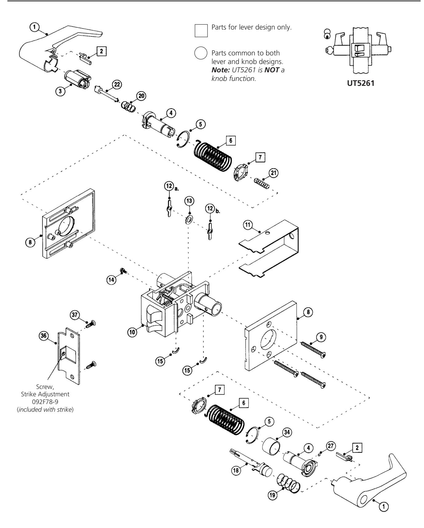

| ITEM | PART NO. | SPECIFY | DESCRIPTION |
|---|---|---|---|
| 1 |
(see chart
below) |
Lever or Knob: Cylinder/Button both
sides |
|
| 2 | 613F02-9 | Lever Insert (gray) | |
| 3 | 2000-052 | fin |
Standard Cylinder
(see page 25 for options) |
| 4 |
188F75-8
188F738 147F088 187F078 |
Lever Shank, outside
Lever Shank, inside Knob Shank, outside Knob Shank, inside |
|
| 5 |
242F50-8
219F80-8 |
Shank Retainer for:
Lever Knob |
|
| 6 |
103F44-8
103F45-8 |
Return Spring
Clockwise (RH) Lever Counter Clockwise (LH) Lever |
|
| 7 | 171F79-8 | Return Spring Anchor | |
| 8 |
144F33
144F34 301F56-7 605F90 415F15 415F16 415F27-7 605F91 |
fin
fin |
Escutcheon (lever trim)
inside outside outside, extended lip inside, lead lined option M28 Escutcheon (knob trim) inside outside outside, extended lip inside, lead lined option M28 |
| 9 | 222F85 | fin | Mounting Screws |
| ITEM | PART NO. | SPECIFY DESCRIPTION | |
|---|---|---|---|
| 10 | 496F32 | fin | Chassis |
| 11 | 138F88-8 | Chassis Cover | |
| 12 .a | 060F42-8 | Hub | |
| 12 .b | 140F97-8 | Hub | |
| 12 .c | 147F07-8 | Hub | |
| 14 | 249F76-8 | Screw, fixed escutcheon | |
| 15 | 078F07-8 | Grip Retainer | |
| 16 | 078F08-8 | Grip Retainer Ring | |
| 17 | 401F08 | fin | Sleeve |
| 21 | 249F77-3 | Spindle Spring | |
| 22 | 144F30-8 | Spindle | |
| 23 | 019F13-7 | Spindle Drive Pin | |
| 24 | 019F11-7 | Spindle Spring Seat | |
| 25 | 144F29-8 | Plug Driver | |
| 26 | 584F81-8 | Plug Diver Assy. Follower | |
| 28 | 168F81-8 | Plug Diver Assy. | |
| 36 | 236L75M020 | fin |
ANSI Strike
(see page 25 for options) |
| 37 | 480F70 | fin | Screw Packet for Strike |
Lever ( specify finish )
Note: Levers are handed.
RH lever: Clockwise rotation. For outside of RH or RHR locks and inside of LH or LHR locks.
LH lever: Counter-clockwise rotation. For outside of LH or LHR locks and inside of RH or RHR locks.
| Regular | Tactile Warning | |||
|---|---|---|---|---|
| Essex (RH) | Essex (LH) | Essex (RH) | Essex (LH) | |
|
Cylinder or Button
6-Pin IC 7-Pin IC |
582F11-2
489F88-2 613F22-2 |
582F12-2
489F89-2 613F23-2 |
582F13-2
549F35-2 613F24-2 |
582F14-2
549F36-2 613F25-2 |
Knobs ( specify finish )
| Regular | Tactile Warning | |||
|---|---|---|---|---|
| Global | Belmont | Global | Belmont | |
|
Cylinder or Button
6-Pin IC |
383F65
482F75 |
406F32
438F79 |
575F57
577F54 |
575F63
577F59 |
The warranty on Corbin Russwin products becomes void if the product is modified in any way, regardless of whether the modifications causes or contributes to any alleged defect. If a Corbin Russwin product is modified it may no longer meet industry certification and quality control standards applicable to the original product and is no longer a genuine Corbin Russwin product.

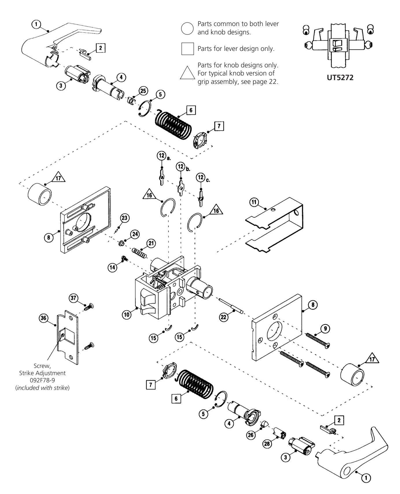

| ITEM | PART NO. | SPECIFY | DESCRIPTION |
|---|---|---|---|
| 1 |
(see chart
below) |
Lever or Knob: Cylinder/Button
both sides |
|
| 2 | 613F02-9 | Lever Insert (gray) | |
| 3 | 2000-052 | fin |
Standard Cylinder
(see page 25 for options) |
| 4 |
102F27-8
287F60-8 069F78-8 144F89-8 |
Lever Shank, outside
Lever Shank, inside Knob Shank, outside Knob Shank, inside |
|
| 5 |
242F50-8
219F80-8 |
Shank Retainer for:
Lever Knob |
|
| 6 |
103F44-8
103F45-8 |
Return Spring
Clockwise (RH) Lever Counter Clockwise (LH) Lever |
|
| 7 | 171F79-8 | Return Spring Anchor | |
| 8 |
144F33
144F34 301F56-7 605F90 415F15 415F16 415F27-7 605F91 |
fin
fin |
Escutcheon (lever trim)
inside outside outside, extended lip inside, lead lined option M28 Escutcheon (knob trim) inside outside outside, extended lip inside, lead lined option M28 |
| 9 | 222F85 | fin | Mounting Screws |
| ITEM | PART NO. | SPECIFY DESCRIPTION | |
|---|---|---|---|
| 10 | 381F30 | fin | Chassis |
| 11 | 138F88-8 | Chassis Cover | |
| 12 | 060F42-8 | Hub | |
| 14 | 249F76-8 | Screw, fixed escutcheon | |
| 15 | 078F07-8 | Grip Retainer | |
| 16 | 078F08-8 | Grip Retainer Ring | |
| 17 | 401F08 | fin | Sleeve |
| 21 | 261F11-8 | Spindle Spring | |
| 25 .a | 144F88-8 | Plug Driver & Spindle Assy. | |
| 25 .b | 145F32-8 | Plug Driver | |
| 29 | 286F50-7 | Pin | |
| 30 | 251F19-8 | Retaining Ring | |
| 31 | 131F27-8 | Coupling | |
| 32 | 194F22-8 | Bushing | |
| 36 | 236L75M020 | fin |
ANSI Strike
(see page 25 for options) |
| 37 | 480F70 | fin | Screw Packet for Strike |
Lever ( specify finish )
Note: Levers are handed.
RH lever: Clockwise rotation. For outside of RH or RHR locks and inside of LH or LHR locks.
LH lever: Counter-clockwise rotation. For outside of LH or LHR locks and inside of RH or RHR locks.
| Regular | Tactile Warning | |||
|---|---|---|---|---|
| Essex (RH) | Essex (LH) | Essex (RH) | Essex (LH) | |
|
Cylinder or Button
6-Pin IC 7-Pin IC |
582F11-2
489F88-2 613F22-2 |
582F12-2
489F89-2 613F23-2 |
582F13-2
549F35-2 613F24-2 |
582F14-2
549F36-2 613F25-2 |
Knobs ( specify finish )
| Regular | Tactile Warning | |||
|---|---|---|---|---|
| Global | Belmont | Global | Belmont | |
|
Cylinder or Button
6-Pin IC |
383F65
482F75 |
406F32
438F79 |
575F57
577F54 |
575F63
577F59 |
The warranty on Corbin Russwin products becomes void if the product is modified in any way, regardless of whether the modifications causes or contributes to any alleged defect. If a Corbin Russwin product is modified it may no longer meet industry certification and quality control standards applicable to the original product and is no longer a genuine Corbin Russwin product.

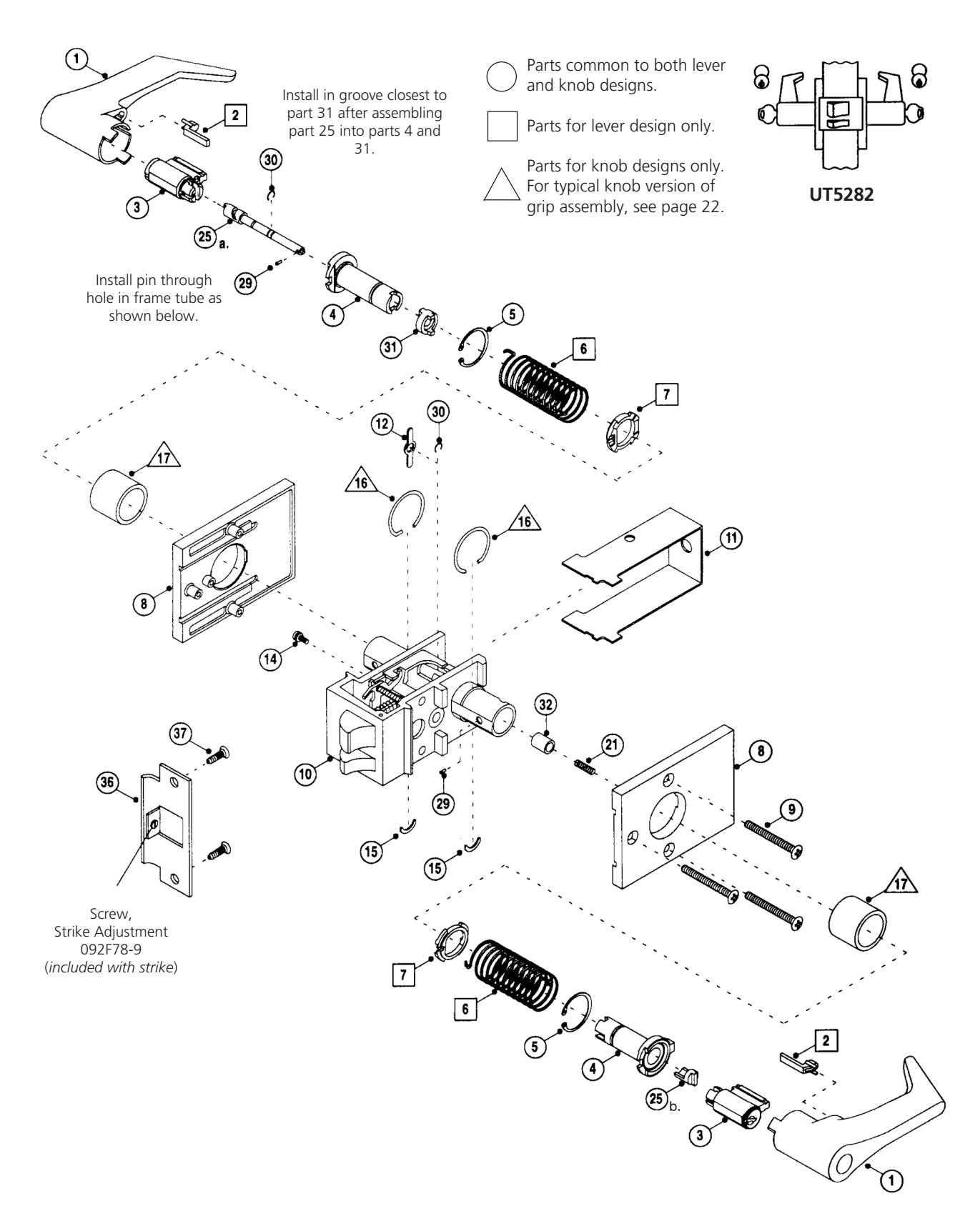

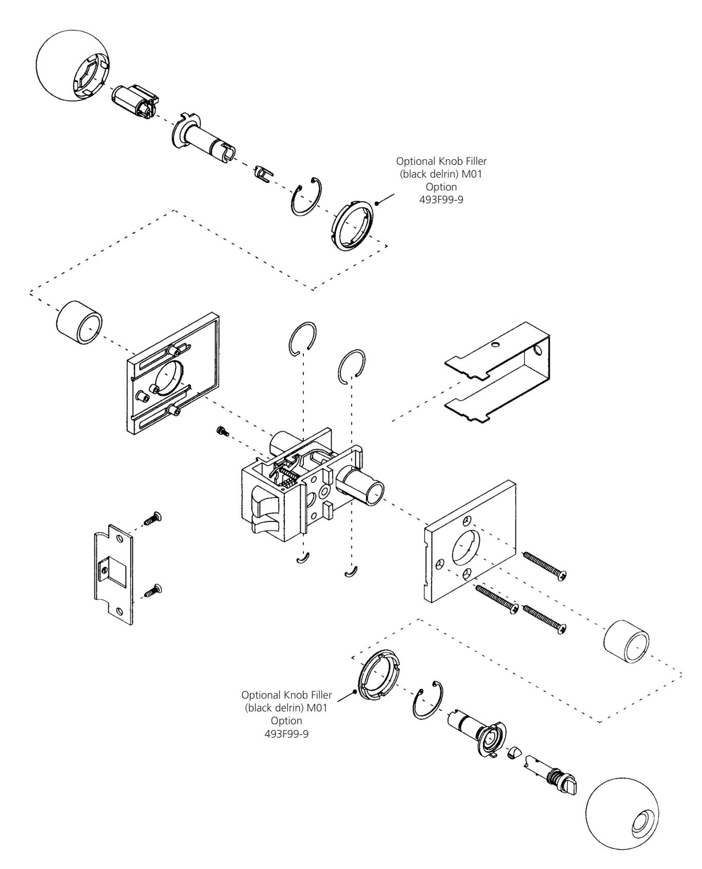

IC Lever Assembly Parts
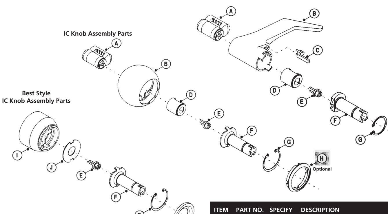
Lever ( specify finish )
| Regular | Tactile Warning | |||
|---|---|---|---|---|
| Essex (RH) | Essex (LH) | Essex (RH) | Essex (LH) | |
|
6-Pin IC
7-Pin IC Best (M08) |
489F88-2
613F22-2 613F42 |
489F89-2
613F23-2 613F43 |
549F35-2
613F24-2 613F442 |
549F36-2
613F25-2 613F452 |
Knobs ( specify finish )
| Regular | Tactile Warning | |||
|---|---|---|---|---|
| Global | Belmont | Global | Belmont | |
|
6-Pin IC
Best (M10) |
482F75
561F19 |
406F32
561F19 |
575F57
N/A |
575F63
N/A |
| ITEM | PART NO. | SPECIFY | DESCRIPTION |
|---|---|---|---|
| A |
8000
8010 8000-7 |
fin
fin fin |
6-Pin Core
High Security Core 7-Pin Core |
| B | (see chart) | Lever or Knob | |
| C | 613F02-9 | Lever Insert (gray) | |
| D |
342F05-2
442F95-2 613F352 |
6-Pin IC Housing
7-Pin IC Housing (lever only) Best |
|
| E |
342F03-2
320F44-2 |
Throw Member for:
Corbin Russwin Core Best Style Core |
|
| F | (see page 24) | Lever or Knob Shank | |
| G |
242F50-8
219F80-8 |
Lever Shank Retainer
Knob Shank Retainer |
|
| H |
493F99-9
378F84 |
fin |
Knob Filler for:
Corbin Russwin, black Delrin (M01 option) Best Style Knob Filler |
| I |
317F71-3
561F19-3 |
fin
fin |
Knob Only
for 6 or 7-Pin Best Style Core Knob Assembly (M10 option) for 6 or 7-Pin Best Style Core Includes items: E, H, I and J (Formerly S-15950) |
| J | 317F68-8 | Knob Plate |
The warranty on Corbin Russwin products becomes void if the product is modified in any way, regardless of whether the modifications causes or contributes to any alleged defect. If a Corbin Russwin product is modified it may no longer meet industry certification and quality control standards applicable to the original product and is no longer a genuine Corbin Russwin product.

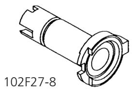
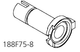
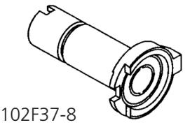
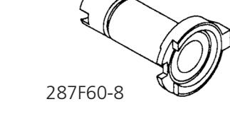
Lever Shanks Knob Shanks
| Function | Outside | Inside |
|---|---|---|
| UT5210 | 102F19-8 | 102F19-8 |
| UT5220 | 114F67-8 | 102F37-8 |
| UT5251 | 188F75-8 | 188F73-8 |
| UT5255 | 605F77-8 | 605F76-8 |
| UT5257 | 188F75-8 | 102F19-8 |
| UT5261 | 156F64-8 | 156F65-8 |
| UT5272 | 188F75-8 | 188F73-8 |
| UT5282 | 102F27-8 | 287F60-8 |
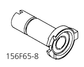
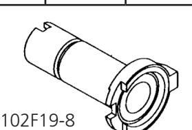
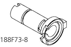
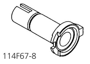
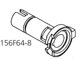
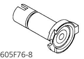
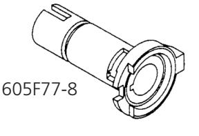
| Function | Outside | Inside |
|---|---|---|
| UT5210 | 060F91-8 | 060F91-8 |
| UT5220 | 202F33-8 | 133F41-8 |
| UT5251 | 187F07-8 | 147F08-8 |
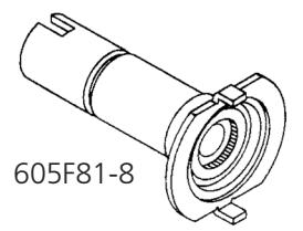
| UT5255 | 605F80-8 | 605F81-8 |
| UT5257 | 187F07-8 | 060F91-8 |
| UT5261 | N/A | N/A |
| UT5272 | 187F07-8 | 147F08-8 |
| UT5282 | 069F78-8 | 144F89-8 |
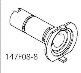
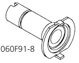
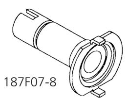
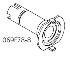
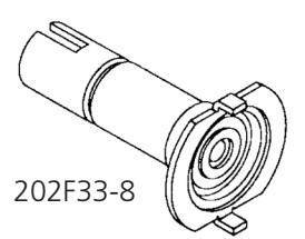
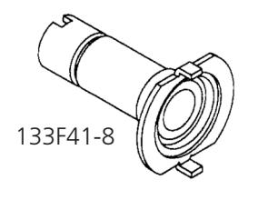
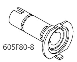
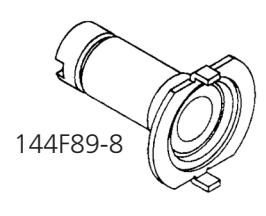
The warranty on Corbin Russwin products becomes void if the product is modified in any way, regardless of whether the modifications causes or contributes to any alleged defect. If a Corbin Russwin product is modified it may no longer meet industry certification and quality control standards applicable to the original product and is no longer a genuine Corbin Russwin product.

|
Strikes
(Specify Finish) |
Description | Part Number |
|---|---|---|
| ANSI Curved Lip Strike (Standard), 1 1/4" lip to center | 236L75M020 | |
|
ANSI Straight Lip Strike for Extended Lip Escutcheon,
15/16" lip to center |
610L43 | |
| ANSI Straight Lip for Pairs of Doors | 610L44 | |
|
ANSI Curved
Lip Strike ANSI Straight Lip Strike for Pairs of Doors |
Curved Lip Box Strike (lip length measured from back to
strike to edge of lip) Lip Lengths: 2" 2 1/8" (std) 2 1/4" 2 1/2" 2 3/4" 3" |
083L96M032
083L96M034 083L96M036 083L96M040 083L96M044 083L96M048 |
| Curved Up |
Straight Lip Box Strike
for extended Lip Escutcheon, 15/16" lip to center |
293L14 |
|
Box Strike
Strike for Pairs of Doors |
Strike for Pairs of Doors | 082L67 |
|
Cylinders
(Specify Finish) |
Standard | Interchangeable Core | Master Ring |
|---|---|---|---|
| Conventional 6-Pin | 2000-052 | 8000 | 2060-052 |
| Conventional 7-Pin | N/A | 8000-7 | N/A |
| High Security | 2010-052 | 8010 | N/A |
| Waldes Tru-Arc Pliers | Description | Part Number |
|---|---|---|
|
For removing and installing large shank retaining
ring to gain access to cylinder of knob locksets |
CT-25 | |
|
CT-25
CT-27 |
For removing and installing the shank retaining
ring of lever locksets |
CT-27 |
|
For installing small retainer on spindle of UT5282
(Waldes applicator #E-015) |
301F59-8 |
| Miscellaneous | Description | Part Number |
|---|---|---|
| Delrin Insert (black) – Option M01 | 493F999 | |
| Spanner Head Screws (specify finish) – Option M02 | 223F29-3 (fin) |

(Parts cross reference does not include parts for product and cylinder options.)
| UT5210 | UT5220 | UT5251 | UT5255 | UT5257 | UT5261 | UT5272 | UT5282 | ||
|---|---|---|---|---|---|---|---|---|---|
| 1 PART NO. | DESCRIPTION Lever or Knob | Sa | ο Pa | arts l | ict | ||||
| 2 613F02-9 | Lever Insert (gray) | • | • | • | • | -130 | • | • | |
| 3 2000-052 | Standard Cylinder | Ť | • | • | • | • | • | • | |
| (4) 060F91-8 | Knob Shank | • | • | ||||||
| 069F78-8 | Knob Shank, Outside | • | |||||||
| 102F19-8 | Lever Shank | • | • | ||||||
| 102F27-8 | Lever Shank, Outside | • | |||||||
| 102F37-8 | Lever Shank, Inside | • | |||||||
| 114F67-8 | Lever Shank, Outside | • | |||||||
| 133F41-8 | Knob Shank, Inside | • | |||||||
| 144F89-8 | Knob Shank, Inside | • | |||||||
| 147F08-8 | Knob Shank, Inside | • | • | ||||||
| 156F64-8 | Lever Shank, Outside | • | |||||||
| 156F65-8 | Lever Shank, Inside | • | |||||||
| 187F07-8 | Knob Shank, Outside | • | • | • | |||||
| 188F73-8 | Lever Shank, Inside | • | • | ||||||
| 188F75-8 | Lever Shank, Outside | • | • | • | |||||
| 202F33-8 | Knob Shank, Outside | • | |||||||
| 287F60-8 | Lever Shank, Inside | • | |||||||
| 605F76-8 | Lever Shank, Inside | • | |||||||
| 605F77-8 | Lever Shank, Outside | • | |||||||
| 605F80-8 | Knob Shank, Outside | • | |||||||
| 605F81-8 | Knob Shank, Inside | • | |||||||
| 219F80-8 | Shank Retainer for Knob | • | • | • | • | • | • | • | |
| 5 242F50-8 | Shank Retainer for Lever | • | • | • | • | • | • | • | • |
| 103F44-8 | Return Spring Clockwise (RH) Lever | • | • | • | • | • | • | • | • |
| 6 103F45-8 | Return Spring Counter Clockwise (LH) Lever | • | • | • | • | • | • | • | • |
| 171F79-8 | Return Spring Anchor | • | • | • | • | • | • | • | • |
| 7 144F33 | Escutcheon (lever) Inside | • | • | • | • | • | • | • | • |
| 8 144F34 | Escutcheon (lever) Outside | • | • | • | • | • | • | • | • |
| 415F15 | Escutcheon (knob) Inside | • | • | • | • | • | • | • | |
| 415F16 | Escutcheon (knob) Outside | • | • | • | • | • | • | • |
The warranty on Corbin Russwin products becomes void if the product is modified in any way, regardless of whether the modifications causes or contributes to any alleged defect. If a Corbin Russwin product is modified it may no longer meet industry certification and quality control standards applicable to the original product and is no longer a genuine Corbin Russwin product.

| (Parts cross reference does not include parts for product and cylinder option | tions. | ||||||||
|---|---|---|---|---|---|---|---|---|---|
| ITEM DART NO | DESCRIPTION | UT5210 | UT5220 | UT5251 | UT5255 | UT5257 | UT5261 | UT5272 | UT5282 |
| ITEM PART NO. 9 222F85 | DESCRIPTION Mounting Screw | • | • | • | • | • | • | • | • |
| 10 198F71 | Chassis | _ | | | • | |||||
| 381F30 | Chassis | • | |||||||
| 496F32 | Chassis | • | • | • | • | ||||
| 496F33 | Chassis | • | |||||||
| 496F34 | Chassis | • | |||||||
| (11) 138F88-8 | Chassis Cover | • | • | • | • | • | • | • | • |
| 12) 060F42-8 | Hub | • | • | • | • | • | • | • | |
| 071F62-8 | Hub | • | |||||||
| 071F63-8 | Hub | • | |||||||
| 081F77-8 | Hub | • | |||||||
| 147F07-8 | Hub | • | • | • | |||||
| 140F97-8 | Hub | • | • | • | |||||
| 208F80-8 | Hub | • | |||||||
| (13) 060F33-8 | Hub Spacer | • | • | ||||||
| 067F42-8 | Hub Spacer | • | |||||||
| 070F42-8 | Hub Spacer | • | |||||||
| 070F43-8 | Hub Spacer | • | |||||||
| 606F03-8 | Hub Spacer | • | |||||||
| (14) 249F76-8 | Screw, Fixed Escutcheon | • | • | • | • | • | • | • | • |
| 15) 078F07-8 | Grip Retainer | • | • | • | • | • | • | • | • |
| 16 078F08-8 | Grip Retainer Ring | • | • | • | • | • | • | • | |
| 401F08 | Sleeve | • | • | • | • | • | • | • | |
| (18) 022F80 | Button Assembly | • | |||||||
| 156F43 | Button Assembly | • | |||||||
| 157F11 | Button Assembly | • | |||||||
| 19 022F72-3 | Button Spring | • | • | ||||||
| 20 060F05-3 | Shoe Spring | • | • | ||||||
| ②1) 071F67-3 | Spindle Spring | • | |||||||
| 218F08-8 | Spindle Spring | • | |||||||
| 261F11-8 | Spindle Spring | • | |||||||
| 249F77-3 | Spindle Spring | • | • | • | • | ||||
The warranty on Corbin Russwin products becomes void if the product is modified in any way, regardless of whether the modifications causes or contributes to any alleged defect. If a Corbin Russwin product is modified it may no longer meet industry certification and quality control standards applicable to the original product and is no longer a genuine Corbin Russwin product.

(Parts cross reference does not include parts for product and cylinder options.)
| ITEM DART NO | DESCRIPTION | UT5210 | UT5220 | UT5251 | UT5255 | UT5257 | UT5261 | UT5272 | UT5282 |
|---|---|---|---|---|---|---|---|---|---|
| ITEM PART NO. (22) 144F30-8 | Spindle | • | • | ||||||
| 156F36-8 | Spindle | • | |||||||
| 201F18-8 | Spindle | • | |||||||
| 335F98-8 | Spindle | • | |||||||
| 606F02-8 | Spindle | • | |||||||
| 23) 019F13-7 | Spindle Drive Pin | • | • | • | |||||
| 24) 019F11-7 | Spindle Spring Seat | • | • | • | |||||
| 25) 144F29-8 | Plug Driver | • | • | • | |||||
| 144F88-8 | Plug Driver and Spindle Assembly | • | |||||||
| 606F32-8 | Plug Driver | • | |||||||
| 606F01-8 | Plug Driver | • | |||||||
| 26) 584F81-8 | Plug Driver Assembly Follower | • | • | • | |||||
| 27) 156F83-7 | Pin | • | |||||||
| 28) 168F81-8 | Plug Driver Assembly | • | • | ||||||
| 29 286F50-7 | Pin | • | |||||||
| 30 251F19-8 | Retaining Ring | • | |||||||
| 31) 131F27-8 | Coupling | • | |||||||
| 32) 194F22-8 | Bushing | • | |||||||
| (33) 107F93-8 | Spring | • | |||||||
| (34) 019F15-2 | Shank Sleeve | • | |||||||
| (35) 398F43-8 | Emergency Key | • | |||||||
| 36) 236L75M020 | ANSI Strike | • | • | • | • | • | • | • | • |
| (37) 480F70 | Screw Packet for Strike | • | • | • | • | • | • | • | • |
The warranty on Corbin Russwin products becomes void if the product is modified in any way, regardless of whether the modifications causes or contributes to any alleged defect. If a Corbin Russwin product is modified it may no longer meet industry certification and quality control standards applicable to the original product and is no longer a genuine Corbin Russwin product.

Periodic adjustment and maintenance will substantially lengthen the life of the lockset and ensure the best possible trouble-free operation.
Time frames in the following maintenance items are based on normal frequency of operation. For high traffic or high abuse applications, perform suggested maintenance more frequently.
If you have questions regarding installation or adjustment, contact an authorized Corbin Russwin distributor or local sales representative.
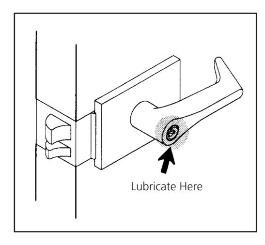
LUBRICATE CYLINDER R
Lubricate (conventional) cylinder with small amount of KeyLube by Medeco® every six months. Petroleum based liquid spray lubricants such as KeyLube by Medeco® should never be mixed with dry lubricants.
LUBRICATE MOVING PARTS R
Lubricate moving parts of inside and outside chassis with a small amount of grease or other petroleum lubricant every two years.
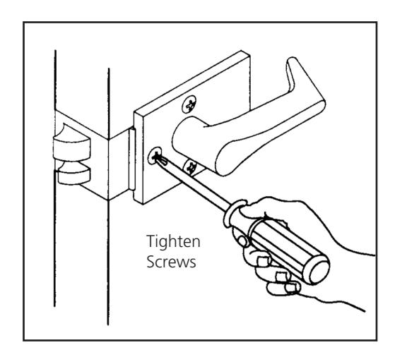
TIGHTEN SCREWS R
Check lockset for secure fastening to door once a year. Tighten throughbolts as needed.
CARE FOR LEVERSET FINISH R
Clean leverset using only a soft, damp cloth. Using lacquer thinners, caustic soaps, abrasive cleaners or polishes could damage the coating, resulting in tarnishing.
The warranty on Corbin Russwin products becomes void if the product is modified in any way, regardless of whether the modifications causes or contributes to any alleged defect. If a Corbin Russwin product is modified it may no longer meet industry certification and quality control standards applicable to the original product and is no longer a genuine Corbin Russwin product.

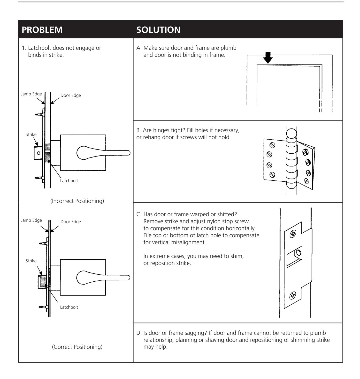

| PROBLEM | SOLUTION |
|---|---|
| 2. Key operates with difficulty. |
A. Is latch binging due to door sag or
misalignment of latch and strike? (See 1A and 1C) B. Are silencers correct size? C. Is weatherstripping causing latch to bind? D. Lubricate keyway. Do not use petroleum products. Apply powdered graphite to key and move slowly in and out. For high security cylinders, spray Poxylube™ into keyway and move key in and out. E. Key may be cut out of tolerance. Use calipers or micrometer to check key against specifications in Corbin Russwin Cylinder manual. Replace key if necessary. F. Cylinder may be improperly combinated. Dismantle cylinder (locksmiths only!), measure all pins and compare to published factory specifications. Recombinate if necessary. |
| 3. Latchbolt does not deadlock |
A. Is strike out of line or is gap between door and jamb too great?
B. Realign strike or shim strike out towards flat area of latchbolt. Jamb Edge Door Edge Jamb Edge Door Edge Latchbolt Strike Strike Latchbolt Deadlocking Deadlocking Latch Latch (If strike is correctly aligned, latchbolt will deadlock) |

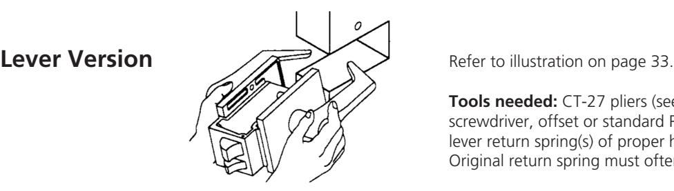
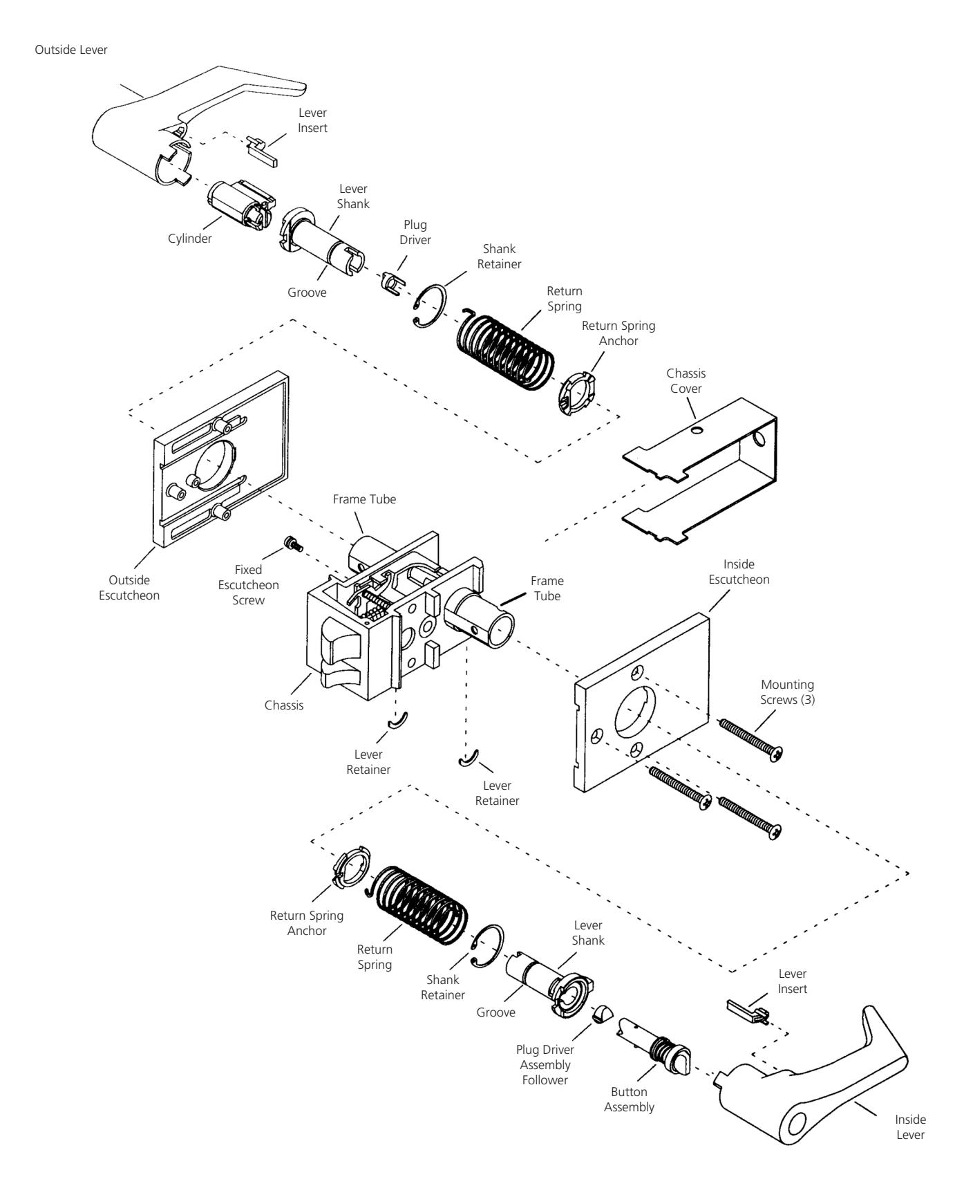
Tools needed: CT-27 pliers (see page 25), small flat blade screwdriver, offset or standard Phillips screwdriver, and spare lever return spring(s) of proper hand of lever(s) to be rekeyed. Original return spring must often be destroyed to remove it.
- 1. Remove all visible screws from escutcheons. Push outside escutcheon away from door surface to clear lugs. Pull lock from edge of door.
- 2. If lockset function permits, unlock lever with button inside or key.
- 3. Remove chassis cover. Gently pry edges loose with small screwdriver while pulling cover away from chassis.
- 4. Door hand and bevel determine which escutcheon is fixed.
If outside escutcheon is loose , pry lever stop away from frame to expose crescent-shaped lever retainer in slot of frame tube. Using small screwdriver, pry retainer out of slot.
If outside escutcheon is fixed , use offset screwdriver to remove Phillips head screw, either from inside of frame or by using access hole in opposite frame wall.
If no offset screwdriver is available, loose escutcheon and opposite lever must be removed to expose access hole in opposite frame wall for standard phillips screwdriver. With screw removed and
escutcheon now loose, pry lever stop away from frame to expose crescentshaped lever retainer in slot of frame tube. Using small screwdriver, pry retainer out of slot.
5. For all functions except UT 5282 ( store door ), skip to step 6. For UT5282, remove small retainer ( item #30 on exploded view page ). This can be challenging so be patient. With small screwdriver, rotate retainer around spindle until its opening is in position of easiest access. Use second small screwdriver with first screwdriver to spread
retainer and remove it from spindle.
- 6. Pull lever handle, return spring and spring anchor off frame. Since spring is wound, rotate lever in appropriate direction to unwind spring. Remove lever stop from spring.
- 7. Note orientation of hooks on ends of spring in illustration. One hook is engaged in slot in shank. Twist and "snap" spring to disengage it; then remove it. If spring bends or deforms, it must be replaced on reassembly. Since spring and lever are both handed, set them aside together.
- 8. Remove gray insert from lever, ( see illustration ). Using Waldes Tru-Arc pliers ( Cat. No. CT-27 ), remove retaining ring from groove inside lever. Remove shank, plug driver and cylinder.
To Reassemble
- 1. Insert cylinder into lever. Be sure plug head seats properly in lever. Insert lever shank, making sure locating tab on shank flange aligns with slot in lever.
- 2. Install Waldes ring, beveled side up, into groove inside lever. Shank and cylinder must be properly to ensure proper engagement of Waldes ring. Rotate Waldes ring so opening aligns with notch in shank flange. Opening must be clear to accept hook of return spring in Step 3.
- 3. Install gray insert into lever. Insert lever return spring, large hook down, into slot in shank and twist spring to lock hook into place.
- 4. Place escutcheon onto lever and shank.Insert short hook of spring into slot of lever stop. Holding lever, spring and lever stop together with escutcheon, slide lever shank into frame tube. Align flat on inside of spring anchor with flat on frame tube. Wind spring one turn in appropriate direction, depending on hand. Push lever and shank assembly into frame tube until groove milled into lever shank aligns with slot in frame tube.
- 5. Press lever retainer firmly into slot. Be sure retainer seats completely to secure shank to frame tube. Stake lever retainer into frame tube slot by tapping screwdriver or punch into frame tube next to retainer. Caution: too much force may deform tube and prevent smooth lever operation.
- 6. If both levers were removed, reinstall second lever, repeating steps 4 and 5.
- 7. For all functions except UT5282 ( store door ), proceed to step 8. For UT5282, small retainer removed in step 2 must be reinstalled. The can be very difficult without Waldes ring applicator.
- 8. If outside escutcheon is to be fixed, use long nose pliers to start Phillips screw through frame into escutcheon. Using offset screwdriver, tighten screw making sure escutcheon is properly seated on frame.
- 9. Test operation of all keys, buttons and levers. Install chassis cover and throughbolts.
The warranty on Corbin Russwin products becomes void if the product is modified in any way, regardless of whether the modifications causes or contributes to any alleged defect. If a Corbin Russwin product is modified it may no longer meet industry certification and quality control standards applicable to the original product and is no longer a genuine Corbin Russwin product.


Knob Version
Horizontal Keyway Locksets Only. For locksets with vertical keyway see pages 36 and 38.
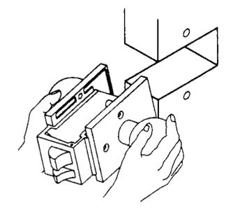
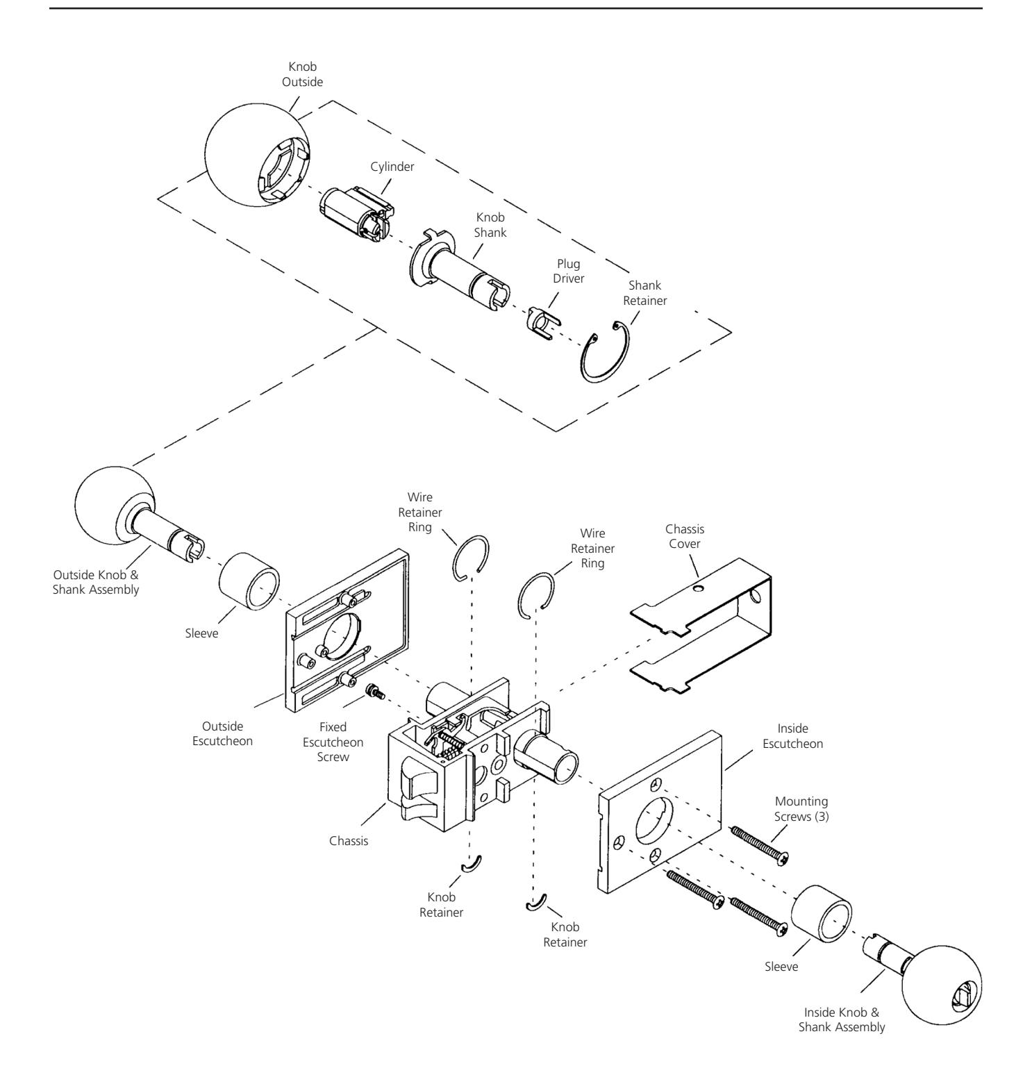
Refer to illustration on page 35.
Tools needed: CT-25 pliers, small flat blade screwdriver, and offset or standard Phillips screwdriver. For UT5282 only: Waldes applicator E-015 (301F59-8) see page 25.
- 1. Remove all visible screws from escutcheons. Push outside escutcheon away from door surface to clear lugs. Pull lock from edge of door.
- 2. If lockset function permits, unlock knob with button inside or key.
- 3. Remove chassis cover. Gently pry edges loose with small screwdriver while pulling cover away from chassis.
- 4. Door hand and bevel determine which escutcheon is fixed.
If outside escutcheon is loose , pry wire retainer ring off to expose crescentshaped knob retainer in slot of frame tube. Using small screwdriver, pry retainer out of slot.
If outside escutcheon is fixed , use offset screwdriver to remove phillips head screw, either from inside of frame or by using access hole in opposite frame wall. If no offset screwdriver is available, loose escutcheon and opposite knob must be removed to expose access hole in opposite frame wall for standard Phillips screwdriver.
With screw removed and escutcheon now loose, pry wire retainer ring off to expose crescent-shaped knob retainer in slot of frame tube. Using small screwdriver, pry retainer out of slot.
- 5. For all functions except UT 5282 ( store door ), skip to step 6. For UT 5282, remove small retainer ( item #30 on exploded view page ). This can be challenging, so be patient. With small screwdriver, rotate retainer around spindle until its opening is on position of easiest access. Use second small screwdriver with first screwdriver to spread retainer and remove it from spindle.
- 6. Remove knob assembly.
- 7. Using Waldes Tru-Arc pliers ( Cat No. CT-25 ), remove large retaining ring from groove inside knob. Remove shank, plug driver and cylinder.
To Reassemble
- 1. Insert cylinder into knob. Be sure plug head seats properly in hole. Insert knob shank.
- 2. Install Waldes ring, beveled side up into groove inside knob.
- 3. Slip retaining ring over frame tube. Place escutcheon onto knob and shank. Push knob and shank assembly into frame tube until slot milled into knob shank aligns with slot in frame tube. Press crescent-shaped knob retainer firmly into slot. Be sure retainer seats completely to secure shank to frame tube.
- 4. Snap wire ring into position over knob retainer.
- 5. If outside escutcheon is to be fixed, use long nose pliers to start Phillips screw through frame into escutcheon. Using offset screwdriver, tighten screw making sure escutcheon is properly seated on frame.
- 6. If both knobs were removed, reinstall other knob repeating steps 3 and 4.
- 7. For all functions except UT5282 ( store door ) proceed to step 8. For UT5282, small retainer removed in step 5 ( above ) must be reinstalled. This can be very difficult without Waldes ring applicator 301F59-8.
- 8. Test all operation of keys, buttons and knobs. Install chassis cover and throughbolts.
The warranty on Corbin Russwin products becomes void if the product is modified in any way, regardless of whether the modifications causes or contributes to any alleged defect. If a Corbin Russwin product is modified it may no longer meet industry certification and quality control standards applicable to the original product and is no longer a genuine Corbin Russwin product.


For Corbin 2000/2200/2400 and 500 Series (1899-1963) Vertical Keyway
Tools needed: 1/8" and 1/4" flat blade screwdrivers, needle nose pliers and a plastic or rawhide mallet.
Caution! No replacement parts are available for this lock. Be very careful not to damage or distort any parts.
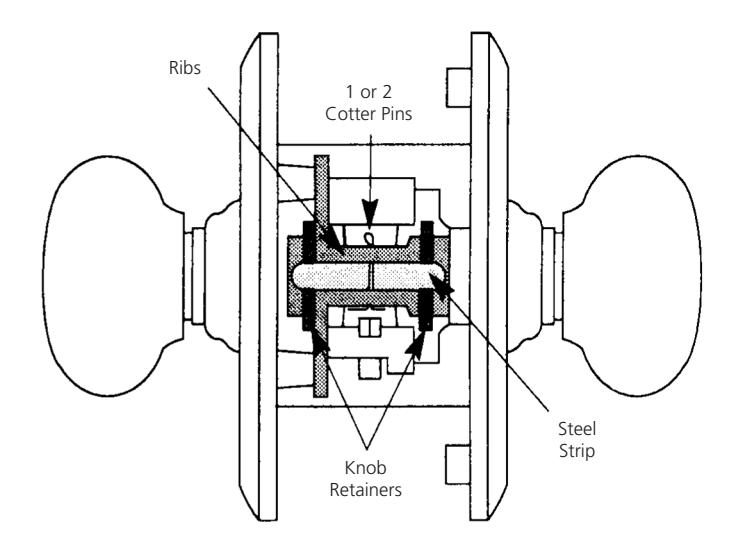
Exposed Mechanism on end of chassis opposite latchbolt
- 1. Remove thru-bolt and remove all escutcheon screws on both sides of door. Pull lock from edge of door.
- 2. Remove chassis cover. Gently pry edges loose with small screwdriver while pulling cover away from chassis.
- 3. Observe exposed mechanism on end of chassis OPPOSITE latch bolt. For this model, a Cotter key passes through ribs in the chassis and covers strip of steel with rounded ends. If chassis is not constructed this way, you are reading wrong set of instructions.
Before removing Cotter key, turn knob(s) and observe orientation of hubs and any other small parts directly connected with knob shanks. These parts may fall out when knob(s) are removed and you will need to reinstall them correctly. Make sketch if desired.
Depending on function of lock, unlock knobs by pressing stopworks button on lock front, by turning knurled ring around inside knob shank, or by using key. This may not be possible on
certain function with rigid knobs.
- 4. Remove cotter key and steel strip under it. If only one knob is to be removed, locate its flat steel retaining plate and remove it. Leave retainer in place for other knob.
- 5. To avoid spilling parts from chassis, grasp lockset by escutcheons and stand it on knob which will remain in place. Support lockset so escutcheons are parallel with work surface, and knob to be removed faces up.
- 6. Note orientation of keyway for proper handling during reassembly. Slowly pull knob off.
- 7. Remove cap from back of knob. If loose, it may have remained on trim as knob was removed. If stuck, rap end of knob shank (not cap!) with plastic or rawhide mallet to jar cap loose. If it has become sealed in place by paint, lacquer or brass polish, it may be necessary to pry it loose with small screwdriver.
- 8. Remove two shank screws which are now exposed. Early models have only
one screw.
9. Unscrew shank from knob and remove cylinder. If shank is stuck, rap area with plastic mallet to jar loose. If this fails, knob may be held snugly in vise with protective cloth. However, remember iron knobs can crack or break and brass knobs may become distorted if abused. Place screwdriver shaft across slot in end of knob shank to turn. If shank still does not unscrew, soak knob assembly in penetration oil or use ultra-sonic cleaner. Rap again.
On reassembly, be sure screw hole(s) in knob shank align with holes in knob before installing screws.
10. If cylinder must be dismantled, drive out actuator retaining pin. This pin also serves as plug retainer. LEAVE KEYS OUT of cylinder until you are ready to rekey it.
Caution: If you are rekeying several of these cylinders, keep all major components of each cylinder together. Mixing parts may result in end play of plug, making it necessary to "pinch" key to remove it.
Most cylinders used in these locks are master ring cylinders with X Class keyways and require .509" diameter plug follower. Refer to Corbin Russwin Cylinder Manual for cylinder combinating instructions, including all pin lengths and key bitting specifications.
11. Clean all parts, including inside of knob shank hole in escutcheon, and reverse these steps for reassembly. Use only dry powdered graphite to lubricate cylinder. Lubricate lockset parts as required.
The warranty on Corbin Russwin products becomes void if the product is modified in any way, regardless of whether the modifications causes or contributes to any alleged defect. If a Corbin Russwin product is modified it may no longer meet industry certification and quality control standards applicable to the original product and is no longer a genuine Corbin Russwin product.

For Corbin 700/Russwin 1600 Series "Baby" Unit Lock- Horizontal Keyway
Tools needed: 1/8" and 1/4" flat blade screwdrivers, needle nose pliers and a plastic or rawhide mallet.
Caution! No replacement parts are available for this lock. Be very careful not to damage or distort any parts.
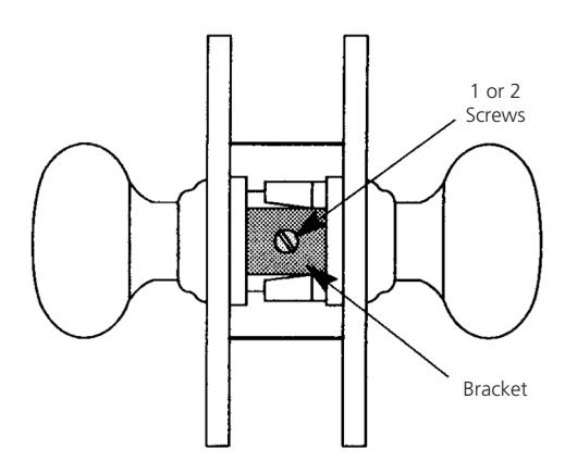
Exposed Mechanism on end of chassis opposite latchbolt
- 1. Remove all escutcheon screws or thrubolts above and below knob on both sides of door. Loosen thru-bolt on inside near latch. Pull lock from edge of door.
- 2. Remove chassis cover. Gently pry edges loose with small screwdriver while pulling cover away from chassis.
- 3. Observe exposed mechanism on end of chassis OPPOSITE latch bolt. For this model, one or two screws pass through a bracket-shaped steel knob retainer. If chassis is not constructed this way, you are reading wrong set of instructions.
Before removing bracket screw(s), turn knob(s) and observe orientation of hubs and any other small parts directly connected with knob shanks. These parts may fall out when knob(s) are removed and you will need to reinstall them correctly. Make sketch if desired.
Depending on function of lock, unlock knob with inside turn button or by using key. This is not be possible on storeroom function with rigid outside knob.
- 4. Remove bracket screw(s). On reassembly, test all operations of both knobs before reinstalling screw(s).
- 5. To avoid spilling parts from chassis, grasp lockset by escutcheons and stand it on knob which will remain in place. Support lockset so escutcheons are parallel with work surface, and knob to be removed faces up.
- 6. Note orientation of keyway for proper handing during reassembly. Remove bracket and slowly pull knob off.
- 7. Remove cap from back of knob. If loose, it may have remained on trim as knob was removed. If stuck, rap end of knob shank ( not cap! ) with plastic or rawhide mallet to jar cap loose. If it has become sealed in place by paint, lacquer or brass polish, it may be necessary to pry it loose with small screwdriver.
- 8. Remove shank screws which are now exposed. Older model has two screws and newer model has one screw.
- 9. Unscrew shank from knob and remove cylinder. If stuck, place screwdriver shaft across slot in end of knob shank to turn. On reassembly, be sure screw hole(s) in knob shank align with holes in knob before installing screws.
- 10. If cylinder must be dismantled, drive out actuator retaining pin. This pin also serves as plug retainer. LEAVE KEYS OUT of cylinder until you are ready to rekey it.
Caution: If you are rekeying several of these cylinders, keep all major components of each cylinder together. Mixing parts may result in end play of plug, making it necessary to "pinch" key to remove it.
Most cylinders used in these locks are master ring cylinders with X Class keyways with .509" diameter plugs. Refer to Corbin Russwin Cylinder Manual for cylinder combinating instructions, including all pin lengths and key bitting specifications.
11. Clean all parts, including inside of knob shank hole in escutcheon, and reverse these steps for reassembly. Use only dry powdered graphite to lubricate cylinder. Lubricate lockset parts as required.
The warranty on Corbin Russwin products becomes void if the product is modified in any way, regardless of whether the modifications causes or contributes to any alleged defect. If a Corbin Russwin product is modified it may no longer meet industry certification and quality control standards applicable to the original product and is no longer a genuine Corbin Russwin product.

For Russwin 2100/2800 Series Only (1904-1968) Vertical Keyway
Tools needed: 1/8" and 1/4" flat blade screwdrivers, needle nose pliers and a plastic or rawhide mallet.
Caution! No replacement parts are available for this lock. Be very careful not to damage or distort any parts.
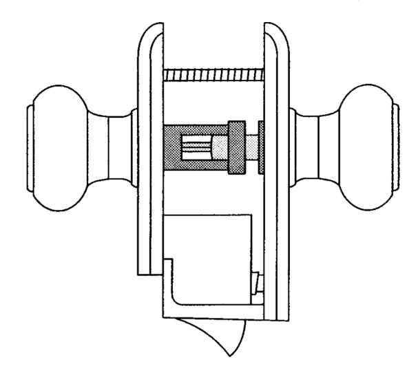
Exposed Mechanism on Top of Lockset
1. Remove thru-bolt and remove all escutcheon screws on both sides of door. Pull lock from edge of door.
If your only task if to fit keys, further disassembly may not be required. If cylinder had never been rekeyed, look through slots in knob shank for original key bitting stamped on square tail piece. Refer to Corbin Russwin Cylinder Manual for bitting prefix and key bitting specifications.
Cylinder removal depends on hand of lockset. If keyed knob has staked hub visible on underside of escutcheon, skip to step 4. If keyed knob is in escutcheon with encased mechanism, continue with step 2.
- 2. Remove screws from plate covering mechanism under escutcheon ( NOT cover of latch assembly ). Before removing exposed parts, make sketch of their orientation for reassembly.
- 3. Remove spring and other parts, laying them out for reassembly. Note orientation of bottom hub with respect to cylinder keyway for proper handing upon reassembly.
- 4. Carefully pry staked hub from base of knob shank. If hub bends, lock will not operate smoothly when reassembled. Also, some knobs are cast iron and staked area may break. Proceed with caution. Upon reassembly, tap hub back into place with plastic or rawhide mallet. If one is not available, use heavy screwdriver handle.
- 5. Using two screwdrivers gently pry retainer ring from around knob shank and remove it. Do not allow wire to become bent or distorted.
- 6. With small screwdriver, disengage three arc-shaped retainers from around knob shank and remove knob assembly from escutcheon.
- 7. Remove cap from back of knob. If stuck, rap end of knob shank ( not cap! ) with a plastic mallet to jar cap loose. If it has become sealed in place by paint or brass polish, it may be necessary to pry it loose with small screwdriver.
- 8. Remove two shank screws which are now exposed.
9. Unscrew shank from knob and remove cylinder. If shank is stuck, rap area with plastic mallet to jar loose. If this fails, knob may be held snugly in vise with protective cloth. However, remember iron knobs can crack or break and brass knobs may become distorted if abused.
For early models with square shank base, use adjustable wrench for extra leverage to unscrew shank. Before applying extreme force to stuck shank, soak assembly in penetrating oil or use ultra-sonic cleaner and rap again with plastic mallet.
On reassembly, be sure screw holes in knob shank align with knob base before reinstalling screws.
10. If cylinder must be dismantled, drive out tailpiece retaining pin. This pin also serves as plug retainer. LEAVE KEYS OUT of cylinder until you are ready to rekey it.
Caution: If you are rekeying several of these cylinders, keep all major components of each cylinder together. Mixing parts may result in end play of plug, making it necessary to "pinch" key to remove it.
Use .522 diameter plug follower. Refer to Corbin Russwin Cylinder Manual for cylinder combinating instructions, including all pin lengths and key bitting specifications.
11. Clean all parts, including inside of knob shank hole in escutcheon, and reverse these steps for reassembly. Use only dry powdered graphite to lubricate cylinder. Lubricate lockset parts as required.
The warranty on Corbin Russwin products becomes void if the product is modified in any way, regardless of whether the modifications causes or contributes to any alleged defect. If a Corbin Russwin product is modified it may no longer meet industry certification and quality control standards applicable to the original product and is no longer a genuine Corbin Russwin product.

All procedures which follow are intended for use only with the current model lockset (Model 68) and the current offering of functions. For obsolete functions or models or designs, use these steps only as a guide and tailor them to your particular lockset. Some obsolete locksets may contain handed parts which are not field reversible.
Changing from Knobs to Levers
This is possible for all functions except UT5261 but it is not practical. Major components must be replaced and the cost can be prohibitive. In addition to the two levers with their shanks, return springs and spring anchors, both escutcheons must also be changed.
Changing Hand of Lockset
Knob Version
Tools required: Phillips screwdriver and large and small slotted screwdriver. For UT5282 (store door) function, Waldes ring applicator E-015 (order as 301F59-8) and second small slotted screwdriver.
To change between LH and RH, or between LHR and RHR, turn lockset upside down. No further action is required.
To change between regular and reverse bevel, the components which must be switched vary by function. For UT5210 (passage) and UT5282 (store door), both sides operate identically, so the only thing which distinguishes regular or reverse bevel is which side of door has exposed screws. For UT5210, this is purely an esthetic concern. For UT5282, security may be a factor in the decision. If neither is a concern for your particular application, there is no need to reverse either of these functions.
For all other functions:
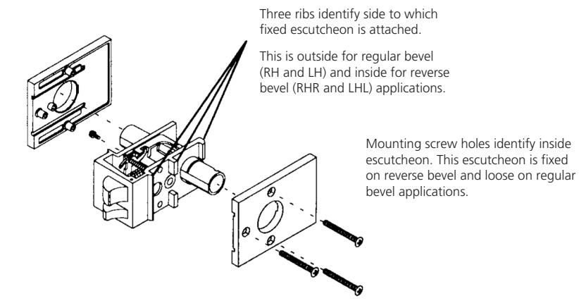
- 1. Remove throughbolts and chassis cover. Notice that one escutheon is loose and the other is fixed. Fixed escutcheon is always attached to chassis on low side of bevel, which is side of chassis with three vertical ribs. This will be outside for regular bevel (RH and LH) and inside for reverse bevel (RHR and LHR). Consequently, fixed side will change during this procedure.
- 2. For all functions except UT5282 (store door), skip to step 3.
For UT5282, remove small retainer (item #30 on exploded view page). This can be challenging, so be patient. With small screwdriver, rotate retainer around spindle until its opening is in position of easiest access. Use second small screwdriver with first screwdriver to spread retainer and remove it from spindle.
- 3. Starting under loose escutcheon , use small screw driver to disengage retainer ring from groove around chassis tube, exposing crescent knob retainer. Remove retainer, then knob assembly with sleeve and escutcheon. If knob contains cylinder or button assembly, do not allow parts to fall out of knob shank. If knob has filler cap (optional on current model) keep it in place. With chassis centered in your work space, lay all parts out in order on side of chassis from which they were removed.
- 4. With all trim removed from first side, locate phillips screw which fastens opposite escutcheon from inside of chassis, Insert screwdriver through access hole in wall of chassis and remove screw and washer.
- 5. With second escutcheon now loose, disengage retainer ring from groove around chassis tube, exposing crescent knob retainer. Remove retainer, then knob assembly with sleeve and escutcheon. If knob contains cylinder or button assembly, do not allow parts to fall out of knob shank. All trim components should now be laid out in order on proper sides of chassis.
For functions other than UT5210 (passage), continue with step 6.
For UT5210, no further disassembly is required. Skip to step 11.
The warranty on Corbin Russwin products becomes void if the product is modified in any way, regardless of whether the modifications causes or contributes to any alleged defect. If a Corbin Russwin product is modified it may no longer meet industry certification and quality control standards applicable to the original product and is no longer a genuine Corbin Russwin product.

Changing Hand of Lockset (cont'd) Knob Version
6. Before proceeding, make mental note of chassis orientation relative to parts already laid out. Use ribbed wall as reference point and remember whether it faced left or right
All functions except UT5210 and UT5282 have a spindle which passes through chassis tube from one side, continues through various hubs and spacers in center of chassis and continues outward through opposite chassis tube. Parts vary by function and so does direction of spindle removal.
Carefully tilt chassis to look into each end of tube and determine which end of spindle is smaller. Hold chassis so small end of spindle points upward. If spindle falls out bottom tube at this to point, lay it out with other parts on proper side of work space and proceed to step7. Otherwise, look for small pin through hole in end of spindle.
Push spindle up from bottom until small pin can be removed through hole in chassis tube. Caution! Cover top end of tube during this process. Some functions have parts which spring off spindle when pin is removed. Spindle should now drop out. If not, gently rotate it until it falls out. Lay spindle and all other parts out in order on proper side(s) of work space.
- 7. Observe order and orientation of hubs and spacers inside chassis. Consult exploded view page for reference. Depress main latch to allow hubs to fall out. Again, lay them out carefully in center of work space from left to right as originally installed. Disassembly is now complete.
- 8. Turn chassis over so opposite tube points up. Depress main latch and reload hubs in same order as removed. Refer to appropriate exploded view page if parts get mixed. Caution: if any hub has a rectangular or "double-D" hole, its orientation is critical. Diagonal flats of hole must face holes in latch tube.
- 9. Install small end of spindle from bottom, passing through all hubs. If spindle has flat sides, verify that hole in spindle faces holes in frame tube. If not, Step 8 was incorrect.
- 10. Supporting spindle with finger in bottom tube, reinstall other parts ( depending on function ) over top end of spindle. In the case of some spring loaded assemblies, use small screwdriver to depress assembly into the chassis far enough to clear hole in end of spindle. Insert retainer pin through frame tube hole and install into spindle.
- Before proceeding, check orientation of all parts in chassis against exploded view page. For comparison, all pages illustrate left hand reverse bevel assembly.
- 11. Remembering original left to right orientation of chassis on work space, turn chassis upside down so knobs and escutcheons are ready to install on opposite sides from original orientation. Note: Opposite escutcheon now becomes fixed ( always attached to ribbed wall of chassis ). Only small screw and washer must switch sides at this point. These must enter from other side of chassis for reassembly.
Observe sides of chassis and locate side with three vertical ribs. Install trim on this side first.
- 12. Place circular wire retainer around frame tube, but do not push all the way into position.
- 13. Put sleeve into back of knob and place that assembly through hole in escutcheon. Slide knob into frame tube as far as it will go. If this knob has cylinder, be sure top of keyway points toward latch ( edge of door ). Groove around the knob shank should now be positioned under the retainer slot in the frame tube.
- 14. Install crescent knob retainer and move retainer ring into place to secure crescent retainer.
- 15. Install fixed escutcheon screw and washer with screwdriver through hole in opposite wall of chassis. (Tip: Use needlenose pliers to position screw inside chassis for screwdriver tip and point lockset upward to start screw into threads.)
- 16. Repeat steps 10, 11, and 12 for remaining side.
- 17. For all functions except UT5282 ( store door ), proceed to step 18. For UT5282, small retainer removed in step 2 must be reinstalled. This can be very difficult without Waldes ring applicator.
- 18. Test operation of all keys, buttons and knobs. Install chassis cover and throughbolts.
The warranty on Corbin Russwin products becomes void if the product is modified in any way, regardless of whether the modifications causes or contributes to any alleged defect. If a Corbin Russwin product is modified it may no longer meet industry certification and quality control standards applicable to the original product and is no longer a genuine Corbin Russwin product.

Changing Hand of Lockset
Lever Version
Because levers are handed, it is not practical to print detailed hand changing instructions. There are too many variations, depending on function and cylinder options.
Use chart below to determine what parts and labor are necessary for the conversion you are attempting. Then, for specific service instructions, refer to previous pages devoted to:
- Disassembly of lever version
- Changing the hand of the knob version.
Note: New levers must be obtained when making the changes in the second half of the diagram below.
|
Levers are Same
(UT5210, UT5272, UT5282, and non-IC UT5251, UT5261) |
|||||||
|---|---|---|---|---|---|---|---|
|
Between LH and
RH or between LHR and RHR |
Between LH and
LHR or between RH and RHR |
Between LH and
RHR or between RH and LHR |
|||||
|
Switch
internal lever components. |
Switch
internal lever components and reverse spindle and/or hubs inside chassis |
Switch
internal lever components and reverse spindle and/or hubs inside chassis, but install levers back on original side of chassis |
|||||
|
Levers are Different
(UT5220, UT5255, UT5257, and IC UT5251, UT5261) |
||||||
|---|---|---|---|---|---|---|
|
Between LH and
RH or between LHR and RHR |
Between LH and
LHR or between RH and RHR |
Between LH and
RHR or between RH and LHR |
||||
|
Transfer internal
components of old levers into NEW LEVERS of opposite handles |
Transfer internal
components of old levers into NEW LEVERS of opposite hands and reverse spindle and/or hubs |
Transfer internal
components of old levers into NEW LEVERS of opposite hands reverse spindle and/or hubs, but install levers back on original side of chassis |
||||
The warranty on Corbin Russwin products becomes void if the product is modified in any way, regardless of whether the modifications causes or contributes to any alleged defect. If a Corbin Russwin product is modified it may no longer meet industry certification and quality control standards applicable to the original product and is no longer a genuine Corbin Russwin product.




In U.S.
Corbin Russwin Architectural Hardware 225 Episcopal Road Berlin, CT 06037 Phone: 800-543-3658 Fax: 800-447-6714 corbinrusswin.com
In Canada
ASSA ABLOY Door Security Solutions Canada 160 Four Valley Drive Vaughan, Ontario Canada L4K 4T9 Phone: 800-461-3007 Fax: 800-461-8989 www.assaabloydss.ca
For more information regarding Corbin Russwin Locksets, Exit Devices, Door Controls and Key Systems, contact your authorized Corbin Russwin Distributor or Sales Representative.