Corbin Russwin SE LP10 ED5000 w, 9600 Trim Installation Instructions_FM385
Open the original PDF document
View PDFCorbin Russwin ASSA ABLOY
FM385 06/20
Attention Installer
Please read these instructions carefully to prevent missing important steps.
Please Note: Improper installations may result in damage to the lock and void the factory warranty.
Important: The accuracy of the door preparation is critical for proper functioning and security of this lock.
Misalignment can cause premature wear and a lessening of security.
For Technical Assistance call Corbin Russwin at 1-800-810-WIRE (9473)

Table of Contents
| 2) Warning3 |
| 3) General Description4 |
| 4 |
| 5) Product Illustrations6 |
| 6) Wiring Diagrams8 |
| 7) Installation Instructions12 |
| 8) MELR Device and Configuration Check24 |
| 9) Door Position Switch (DPS) Installation24 |
| 10) Operational Check25 |

1) Regulatory Compliance
Changes or modifications to this unit not expressly approved by the party responsible for compliance could void the user's authority to operate the equipment.
FCC:
This equipment has been tested and found to comply with the limits for a Class B digital device, pursuant to Part 15 of the FCC Rules. These limits are designed to provide reasonable protection against harmful interference in a residential installation. This equipment generates, uses, and can radiate radio frequency energy and, if not installed and used in accordance with the instructions, may cause harmful interference to radio communications. However, there is no guarantee that interference will not occur in a particular installation. If this equipment does cause harmful interference to radio or television reception, which can be determined by turning the equipment off and on, the user is encouraged to try to correct the interference by one or more of the following measures:
- Reorient or relocate the receiving antenna.
- Increase the separation between the equipment and receiver.
- Connect the equipment into an outlet on a circuit different from that to which the receiver is connected.
- Consult the dealer or an experienced radio/TV technician for help.
Industry Canada:
This Class B digital apparatus meets all requirements of the Canadian Interference Causing Equipment Regulations. Operation is subject to the following two conditions: (1) this device may not cause harmful interference, and (2) this device must accept any interference received, including interference that may cause undesired operation.
Cet appareillage numérique de la classe B répond à toutes les exigences de l'interférence canadienne causant des règlements d'équipement. L'opération est sujette aux deux conditions suivantes: (1) ce dispositif peut ne pas causer l'interférence nocive, et (2) ce dispositif doit accepter n'importe quelle interférence reçue, y compris l'interférence qui peut causer l'opération peu désirée.
This equipment complies with FCC radiation exposure limits set forth for an uncontrolled environment. This equipment should be installed and operated with minimum distance 20cm between the radiator and your body. This transmitter must not be co-located or operating in conjunction with any other antenna or transmitter.
Cet équipement est conforme aux limites d'exposition aux radiations de la FCC définies pour un environnement non contrôlé. Cet équipement doit être installé et utilisé à une distance minimale de 20 cm entre le radiateur et votre corps. Cet émetteur ne doit pas être co-localisé ou fonctionner en conjonction avec une autre antenne ou un autre émetteur.
Under Industry Canada regulations, this radio transmitter may only operate using an antenna of a type and maximum (or lesser) gain approved for the transmitter by Industry Canada. To reduce potential radio interference to other users, the antenna type and its gain should be so chosen that the equivalent isotropically radiated power (e.i.r.p.) is not more than that necessary for successful communication.
Conformément à la réglementation d'Industrie Canada, le présent émetteur radio peut fonctionner avec une antenne d'un type et d'un gain maximal (ou inférieur) approuvé pour l'émetteur par Industrie Canada. Dans le but de réduire les risques de brouillage radioélectrique à l'intention des autres utilisateurs, il faut choisir le type d'antenne et son gain de sorte que la puissance isotrope rayonnée équivalente (p.i.r.e.) ne dépasse pas l'intensité nécessaire à l'établissement d'une communication satisfaisante.
2) Warning

This product can expose you to lead which is known to the state of California to cause cancer and birth defects or other reproductive harm. For more information go to: www.P65warnings.ca.gov.
Ce produit peut vous exposer au plomb qui, dans l'état de la Californie, est reconnu pour causer le cancer, des anomalies congénitales ou d'autres problèmes de reproduction.
Pour plus d'informations, visitez: www.P65warnings.ca.gov.

Any retrofit or other field modification to a fire rated opening can potentially impact the fire rating of the opening, and Corbin Russwin makes no representations or warranties concerning what such impact may be in any specific situation. When retrofitting any portion of an existing fire rated opening, or specifying and installing a new fire-rated opening, please consult with a code specialist or local code official (Authority Having Jurisdiction) to ensure compliance with all applicable codes and ratings.

To avoid possible damage from electrostatic discharge (ESD), some basic precautions should be used when handling electronic components:
- Minimize build-up of static by touching and/or maintaining contact with unpainted metal surfaces such as door hinges, latches, and mounting plates especially when mounting electronic components such as readers and controllers onto the door.
- Leave components (reader and controller) protected in their respective anti-static bags until ready for installation
- Do not touch pins, leads or solder connections on the circuit boards

3) General Description
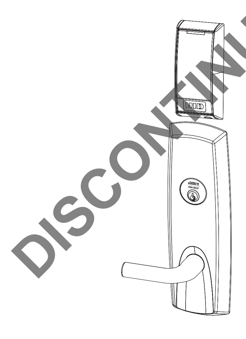
The Corbin Russwin SE LP10 Series exit device is designed to interface with existing Wired Electronic Access Control (EAC) panels. The reader requires 12VDC for power and features HID® multiCLASS SE® technology. The technology is designed around Corbin Russwin's Grade 1 hardware. The exit device comes with touch bar monitoring (REX) and is provided with an external Door Position Switch (DPS). Featuring EcoFlex™ technology, the lock operates from 12-24VDC.
4) Specifications / Features
- Door Thickness 1-3/4" Standard; Can be furnished for other door thicknesses upon request. Consult factory.
- Outside lever controlled by reader or key allows lever to retract latch
- Inside push bar produces REX (request to exit) signal and retracts latch
- Fail Safe or Fail Secure Operation (must specify)
- UL fire listed available
- Wires directly to EAC panels
- Wire from EAC Panel to door must be shielded with a drain. Drain terminated at EAC Panel controller.
- Supports multiple credential formats:
Electrical Specifications
- Reader Draw = 150mA @12 / 24VDC
- Actuator Draw = 400mA inrush / 15mA continuous @12 / 24VDC
- Total System Draw = 550mA @12/24VDC
• 2.4 GHz credential compatibility
- Secure Identity Object<sup>™</sup> (SIO) on Mobile IDs (Bluetooth Smart)
-
13.56 MHz credential compatibility:
- Secure Identity Object™ (SIO) on iCLASS Seos, iCLASS SE/SR, MIFARE DESFire EV1/EV2 and MIFARE Classic (on by default)
- Standard iCLASS Access Control Application, ISO14443A (MIFARE) CSN, ISO14443B CSN, and ISO15693 CSN
- ISO14443A/B (PIV-compatible Transparent FASC-N read) available with SE LP10-F (**not available with Alternate Indicator Configuration**)
- NFC-enabled mobile phones
• 125 kHz credential compatibilty:
• HID Prox®, AWID, EM4102
For Mobile Credential-Enabled versions of this electronic lock (Indicated by "BIPS" in the product order string):
- Mobile Credentials are transmitted to the lock via Bluetooth Smart or NFC ISO/IEC14443 and must use a mobile device enabled with these technologies.
- Credential and mobile device versions are specified by the credential provider.
- User must acquire the latest HID "Mobile Access" application available from Apple iStore or Android PlayStore.
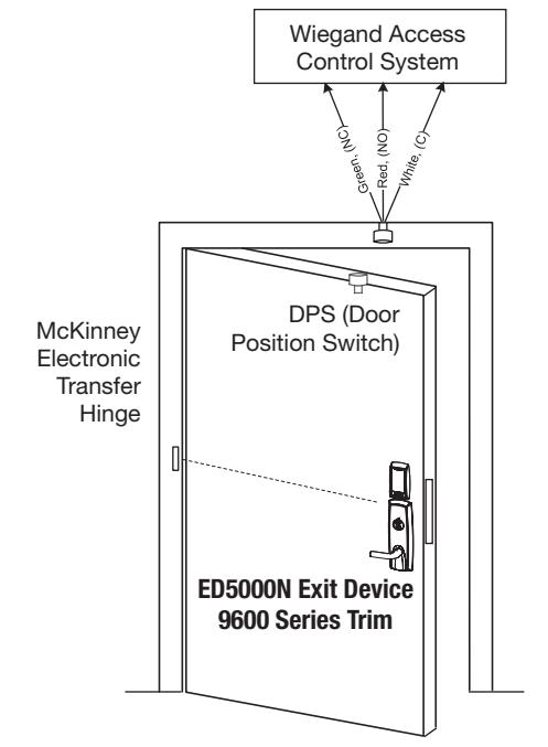
The reader requires 12VDC for power, while the lock accepts 24VDC.

5) Product Illustrations (Rim/CVR/Mortise)
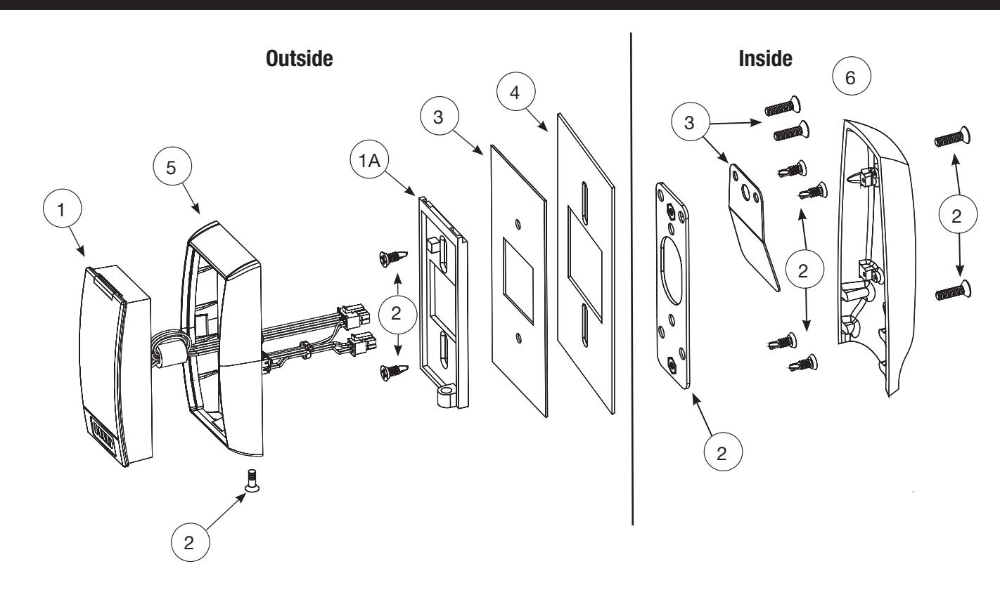
| ITEM | PART # | DESCRIPTION | |
|---|---|---|---|
| 1 | 763F809 | BIPS-B03 Reader and Harness Assembly - Bluetooth (Standard Indicator Configuration) | 1 |
| 763F649 | FIPS-B03 Reader & Harness Assembly - 200 bit Wiegand output | ||
| 763F669 | FIPS-B04 Reader & Harness Assembly - 75 bit Wiegand output | ||
| 763F629 | IPS-B03 Reader & Harness Assembly (Standard Indicator Configuration) | ||
| 784F869 | IPS-B0E Reader & Harness Assembly - (Alternate Indicator Configuration) | ||
| 784F879 | BIPS-B0E Reader & Harness Assembly - Bluetooth (Alternate Indicator Configuration) | ||
| 1A | SE Reader Mounting Plate | 1 | |
| 2 | 763F882 FIN | Mounting Packet | 1 |
| 3 | 763F719 | Fire Plate Packet | 1 |
| 4 | 764F319 | Gasket (for non fire-rated doors) | 1 |
| 5 | 852F269 | Trim Bezel- Black | 1 |
| 6 | 743F282 FIN | Inside Escutcheon | 1 |
Tools Required:
- #2 Phillips Screw Driver (Standard size)
- Flat Blade Screw Driver (Standard size)
- 1/8" Allen Wrench
- TR10 Torx Security Screw Driver

5) Product Illustrations (SVR)
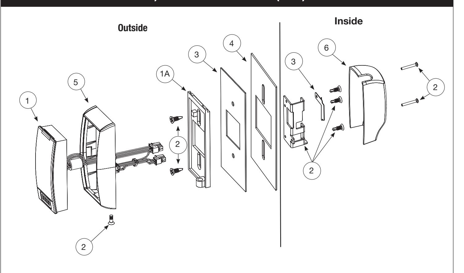
| ITEM | PART # | DESCRIPTION | |
|---|---|---|---|
| 1 | 763F809 | BIPS-B03 Reader and Harness Assembly - Bluetooth (Standard Indicator Configuration) | 1 |
| 763F649 | FIPS-B03 Reader & Harness Assembly - 200 bit Wiegand output | ||
| 763F669 | FIPS-B04 Reader & Harness Assembly - 75 bit Wiegand output | ||
| 763F629 | IPS-B03 Reader & Harness Assembly (Standard Indicator Configuration) | ||
| 784F869 | IPS-B0E Reader & Harness Assembly - (Alternate Indicator Configuration) | ||
| 784F879 | BIPS-B0E Reader & Harness Assembly - Bluetooth (Alternate Indicator Configuration) | ||
| 1A | SE Reader Mounting Plate | 1 | |
| 2 | 763F882 FIN | Mounting Packet | 1 |
| 3 | 763F729 | Fire Plate Packet | 1 |
| 4 | 764F319 | Gasket (for non fire-rated doors) | 1 |
| 5 | 852F269 | Trim Bezel- Black | 1 |
| 6 | 744F762 FIN | Inside Escutcheon (LHR) | 1 |
| 744F772 FIN | Inside Escutcheon (RHR) | 1 |

6) Wiring Diagrams
| Product | 8 PIN CONNECTOR | 4 PIN CONNECTOR | ||||||||||
|---|---|---|---|---|---|---|---|---|---|---|---|---|
| 1-Black | 2-Red | 3-White | 4-Green | 5-Orange | 6-Blue | 7-Brown | 8-Yellow | 1-Violet | 2-Gray | 3-Pink | 4-Tan | |
| ACCESS CONTROL DEVICES: SE LP10 Mortise, ElectroLynx wire Color / Function assignments | ||||||||||||
| SE LP10 | 12VDC | WIEGAND | WIEGAND | RX | RX | EGND | TAMPER | 12/24 VDC | DPS | DPS | ||
| (Reader) | GREEN_LED* | (LOCK RELAY) | ||||||||||
| NEG | POS | DATA_1 | DATA_0 | NO | COM | EGND |
OPEN
COLLECTOR |
NEG | POS | NC | COM | |
| INPUT | ||||||||||||
* Diagrams on following pages
Default Operation Mode:
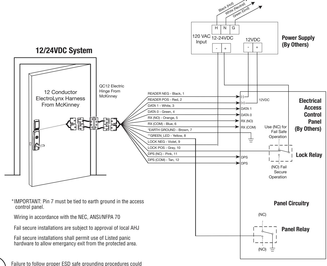
- Red LED 'ON' when powered.
- Presenting a 13.56MHz or 125 kHz credential causes LED to briefly turn green and then return to red state.
- Presenting a FIPS 201 PIV credential causes LED to turn amber as credential is authenticated. Reader emits a short beep when credential is successfully read. Reference Diagram #1.
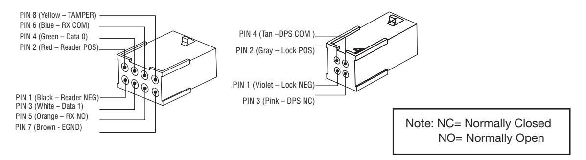
Optional TAMPER Operation Mode:
- Connect Yellow TAMPER wire from ElectroLynx cable to desired EAC panel control line. Reference Diagram #1.
- As appropriate, use the configuration card to activate desired mode on reader.
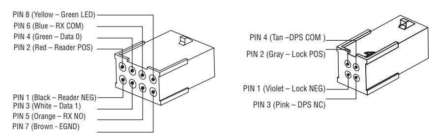
Optional Alternate Indicator Mode:
• Connect GREEN_LED input to switch controlled by panel. Shorting GREEN_LED to READER_NEG (Black) with panel switch will override reader LED to keep it green.

6) Wiring Diagrams (Continued)
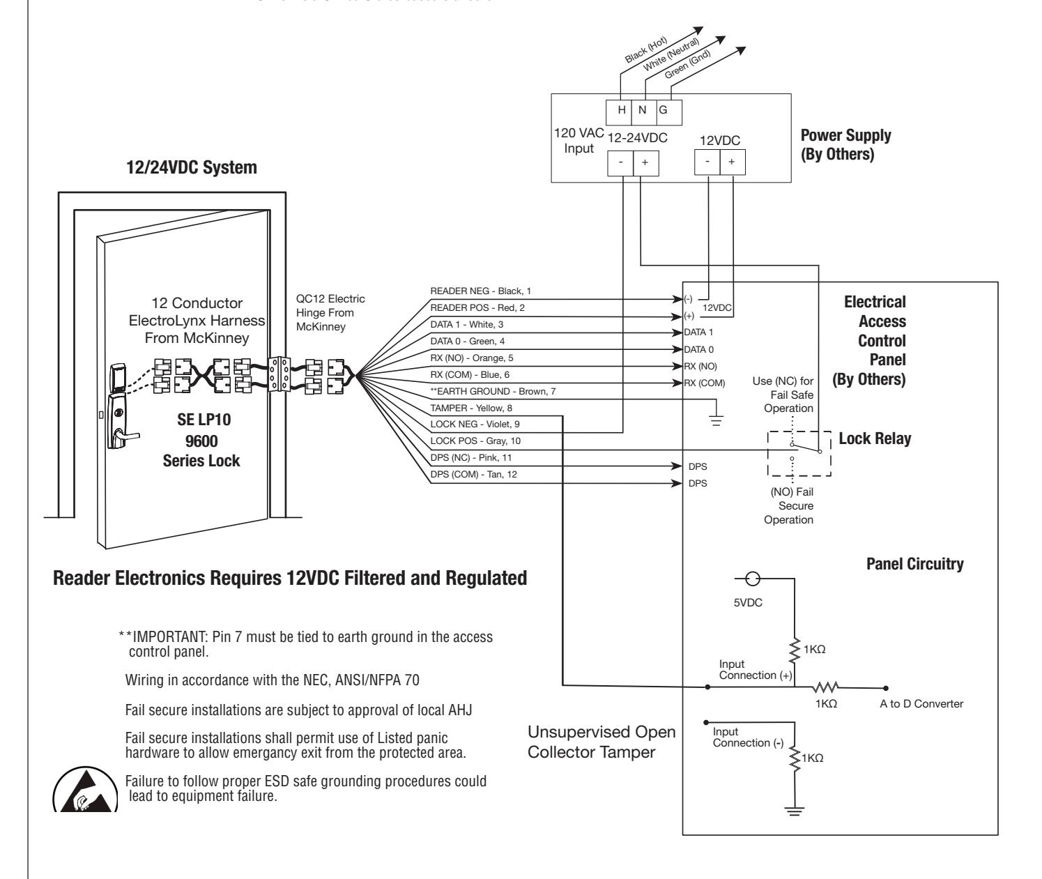
Typical (UL294*-Compliant) SE LP10 Application Diagram #1
Tamper will trigger when reader is removed from door and tamper wiring is connected at the panel.
| 12\ | 1 | 24V | ||
|---|---|---|---|---|
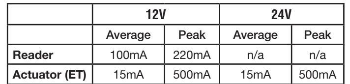
| Average Peak | Average | Peak | ||
| Reader | 100mA 220mA | n/a | n/a | |
| Actuator (ET) | 15mA | 500mA | 15mA | 500mA |
* UL294 is a United States based standard.

6) Wiring Diagrams (Continued)
Alternate Indicator Configuration Application Diagram #2
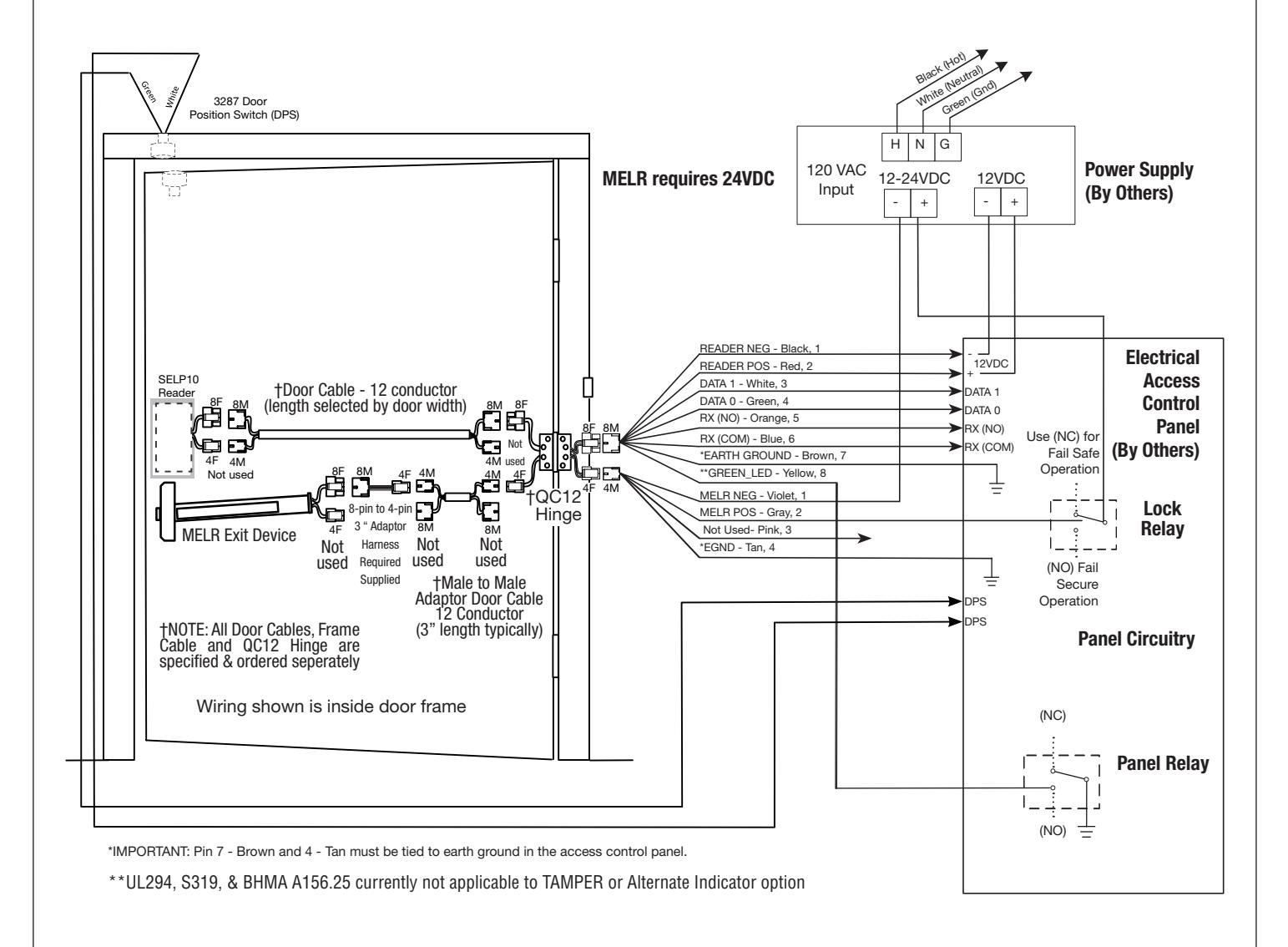
Connect GREEN_LED input to switch controlled by panel. Shorting GREEN_LED to READER_NEG (Black) with panel switch will override reader LED to keep it green.
Reader Electronics Requires 12VDC Filtered and Regulated

Failure to follow proper ESD safe grounding procedures could lead to equipment failure.
** UL294, S319, & BHMA A156.25 currently not applicable to Alternate Indicator option

6) Wiring Diagrams (Continued)
| Product | Product 8 PIN CONNECTOR | 4 | PIN CON | NECTOR | ||||||||
|---|---|---|---|---|---|---|---|---|---|---|---|---|
| 1-Black | 2-Red | 3-White | 4-Green | 5-Orange | 6-Blue | 7-Brown | 8-Yellow | 1-Violet | 2-Gray | 3-Pink | 4-Tan | |
| ACCESS CONTROL DEVICES: SE LP10 Mortise, ElectroLynx wire Color / Function assignments | ||||||||||||
| SE LP10 | /DC | WIEGAND | WIEGAND | RX | RX | EGND | TAMPER |
12/24 VDC
(LOCK RELAY) |
DPS | DPS | ||
| MELR | (Rea | ader) | GREEN_LED* | |||||||||
| NEG | POS | DATA_1 | DATA_0 | NO | COM | EGND |
OPEN
COLLECTOR |
NEG | POS | NC | COM | |
| INPUT | ||||||||||||
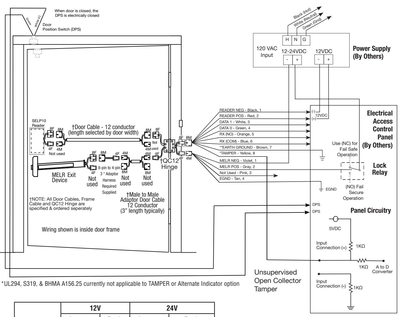
SE LP10 (MELR) Application Diagram #3 (12/24VDC System)
| 12V | 2 | 24V | ||
|---|---|---|---|---|
| Average | Peak | Average | Peak | |
| Reader | 100mA | 220mA | n/a | n/a |
| MELR | n/a | n/a |
250mA
dogged |
1A inrush
600mA during retraction |
Wiring in accordance with the NEC, ANSI/NFPA 70 Fail secure installations are subject to approval of local AHJ Fail secure installations shall permit use of Listed panic hardware to allow emergancy exit from the protected area.

Failure to follow proper ESD safe grounding procedures could lead to equipment failure.
Experience a safer and more open world

6) Wiring Diagrams (Continued)
Alternate Indicator Configuration Application Diagram #4
Connect GREEN_LED input to switch controlled by panel. Shorting GREEN_LED to READER_NEG (Black) with panel switch will override reader LED to keep it green.
Reader Electronics Requires 12VDC Filtered and Regulated
| 12V | I | 24V | ||
|---|---|---|---|---|
| Average Peak | Average | Peak | ||
| Reader | 100mA | 220mA | n/a | n/a |
| MELR | 15mA | 500mA | 15mA | 500mA |

7) Installation Instructions
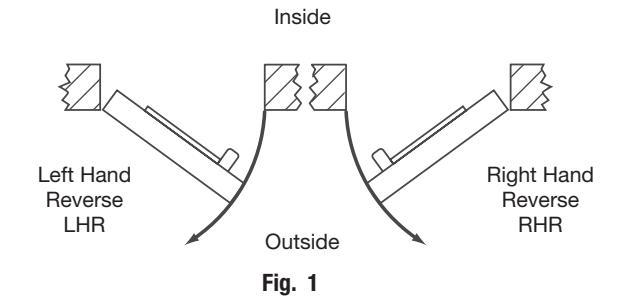
1. Verify Hand and Bevel of door:
Door should be fitted and hung.
Verify box label for size of exit device, function and hand.
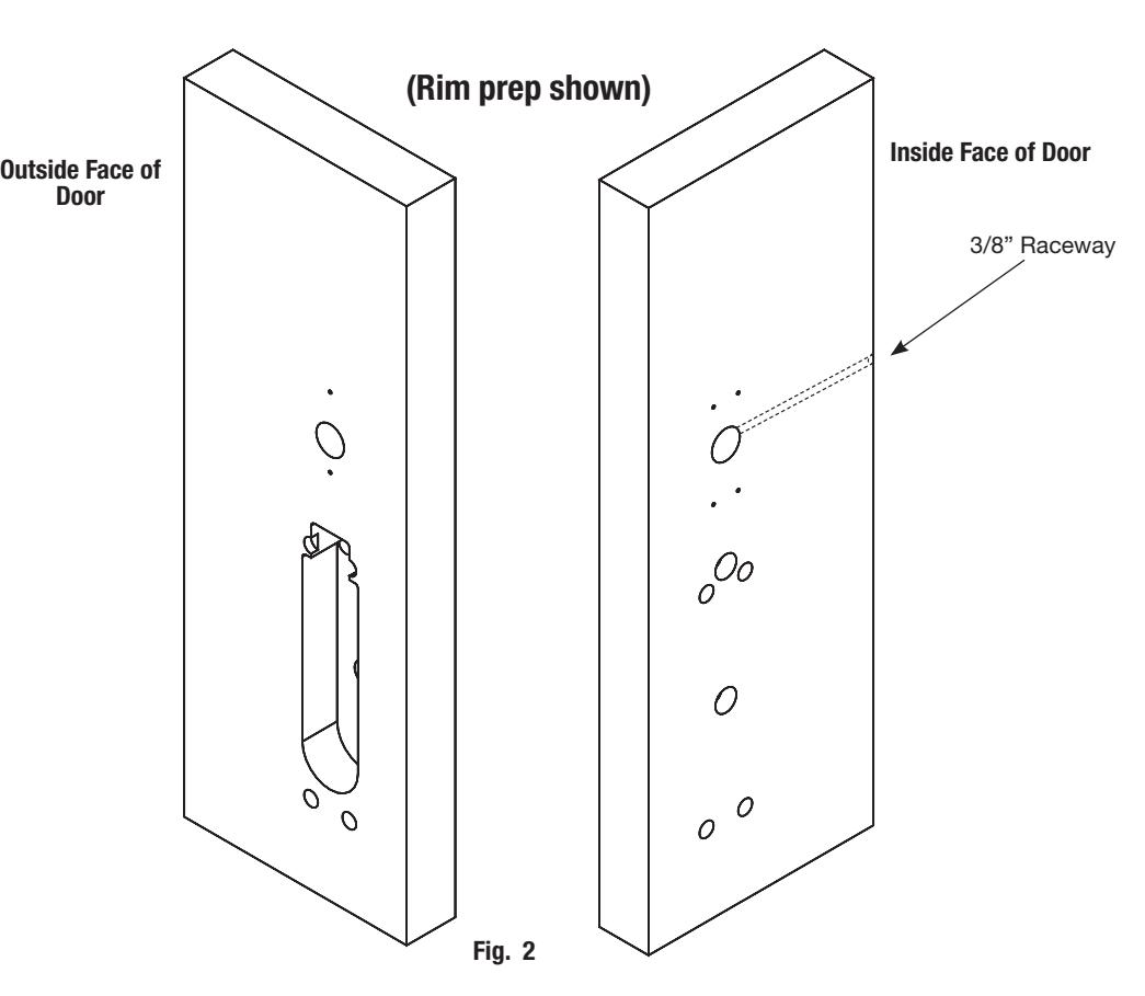
2. Prep door according to supplied door markers:
Outside - FM382 for Rim/SVR/CVR; FM386 for Mortise.
Inside - FM387
NOTE: Reference the following instructions for rail installation:
FM156 Rim (standard)
FM532 Rim (SecureBolt®)
FM164 SVR
FM171 CVR
FM168 Mortise
For door manufacturer templates visit www.corbinrusswin.com and reference template numbers:
| Wood | Metal | ||
|---|---|---|---|
| Rim | T31215 | T31216 | |
| CVR | T31215 | T31216 | |
| SVR |
T31218
T31219 |
||
| Mortise | T31217 | ||

7) Installation Instructions (Continued)
*For non-fire rated interior doors, no fire shield or gasket is required. 1. For fire-rated doors only, install reader backplate and fire shield to door using two (2) #8-18 x 5/8" Phillips flat head self-drilling screws (Fig. 3a). 2. For exterior doors, install reader backplate and gasket using two (2) #8-18 x 5/8" Phillips flat head self-drilling screws (Fig. 3b). 3. For non-fire rated interior doors, no fire shield or gasket is required; simply install backplate using two (2) #8-18 x 5/8" Phillips flat head self-drilling screws. 3. Install Reader Backplate and (Optional*) Fire Shield or Gasket Fig. 3b Gasket (for exterior doors) Reader Backplate Fire plate Outside Face of Door (2) #8 x 5/8" Phillips flat head self-drilling screws Fig. 3a
4. Install SE LP10 Reader and Trim Bezel:

Observe precautions for handling electrostatic sensitive devices. ! If the SE LP10 reader is installed with a module (Fig. 4a), make sure that the reader is powered down when inserting/removing the module; i.e., do not "hot-plug" (remove/insert while reader is powered) module as it may damage the reader.
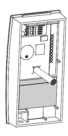
Fig. 4a

7) Installation Instructions (Continued)
4. Install SE LP10 Reader and Trim Bezel (Continued):
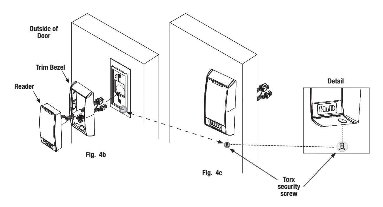
- 1. Fit trim bezel around the reader. Ensure access hole in the bezel aligns with screw hole on reader. The reader should be mounted so holes face bottom of door (Fig 4b).
- 2. Align top of reader with top of backplate. Pivot the reader down until seated. Guide wires as needed to avoid pinching.
- 3. Secure the reader with (1) #6-32 x 3/8" Phillips or anti-tamper security torx screw to the mounting plate (Fig 4b, c).
Rim/SVR/CVR shown, assembly is same for mortise

7) Installation Instructions (Continued)
5. Trim Assembly Instructions:
a. Check cylinder components:
Cylinders longer than 1-1/8" (29mm) require collars. Refer to Cylinder Collar Chart (Fig. 5a).
(for Mortise, skip to Step 6)
b. If required, modify by cutting cylinder tailpiece: Correct length is 1/16" to 3/16" (2 to 5mm) beyond cylinder housing cam.
| Cylinder Collar Chart | ||||||
|---|---|---|---|---|---|---|
|
Cylinder Length
Collar |
||||||
| Inches | Millimeters | |||||
| 1-1/8" | 29mm | None | ||||
| 1-1/4" | 32mm | 422F88* | ||||
| 1-1/2" | 38mm | 686F98* | ||||
*Specify Finish Fig. 5a
-
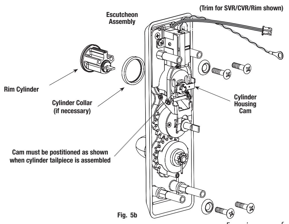
c. Assemble cylinder:
- 1. Insert cylinder housing prongs into matching notches of escutcheon.
- 2. Pass cylinder tailpiece through cylinder collar (if required) and slot in cylinder cam.
- 3. Fasten cylinder in escutcheon recess or collar using 2 mounting screws.
Do not overtighten screws.
d. Escutcheon Assembly (Fig. 5b):
The lever is handed (LHR shown).
Note: Lever Return Spring handing can be identified by color of the spring:
- LHR: Part Number 651F618 (Red)
- RHR: Part Number 651F628 (Blue)

7) Installation Instructions (Continued)
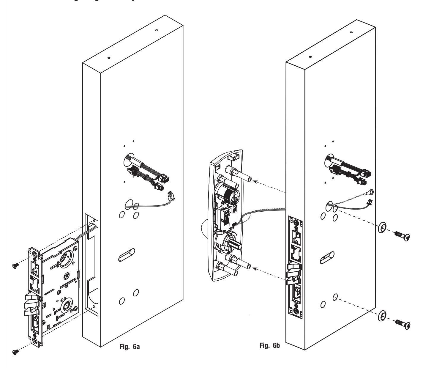
6. Install Mortise and Outside Trim Assembly:
Install mortise lock following FM168 instructions, but do not install armored front at this time.
- a. Feed lock wire through wire harness hole; seat lockbody firmly into mortised pocket (Fig. 6a).
- b. Mount trim to door.
- c. Fasten trim assembly to door using (2) 1/4-20 oval head screws and (2) finish washers (Fig. 6b). Note: Finger tighten only.

7) Installation Instructions (Continued)
6. Install Mortise and Outside Trim Assembly (Continued):
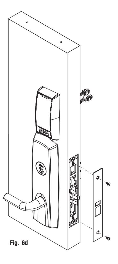
- d. Tighten down set screw to prevent cylinder movement (Fig. 6c).
- e. Install armored front (Fig. 6d).


permission of ASSA ABLOY Access and Egress Hardware Group, Inc. is prohibited.
7) Installation Instructions (Continued)
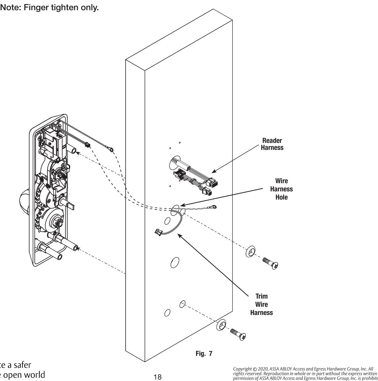
7. Install Outside Trim Assembly (Rim/CVR/SVR):
- a. Make sure tailpiece is oriented vertically.
- b. Feed trim wire harness through wire harness hole (Fig. 7).
- c. Mount trim assembly to door pulling slack wire towards device side of door.
Note: Be careful not to pinch wire harness.
-
d. When mounting trim, lift tailpiece to pass through hole on device side (Fig. 7).
- Note: Ensure tailpiece is still oriented vertically.
- e. Fasten trim assembly to door using (2) 1/4-20 oval head screws and (2) finish washers (Fig. 7).

7) Installation Instructions (Continued)
8. Install Exit Device:
Follow instructions packed with device to secure device to door.
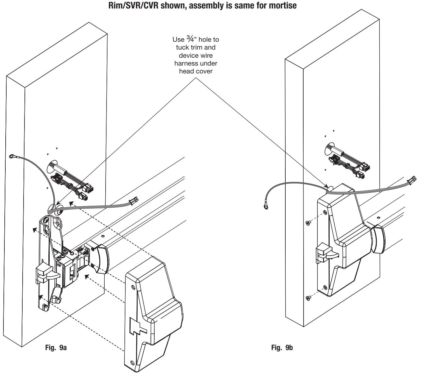
9. Install Head Cover:
- a. Lay wire device harnesses across ¾" hole (Fig. 9a).
- b. Tuck wires into hole when installing cover so that wires are not pinched between head cover and door.
- c. Attach head cover using (2) #8-32 flat head screws (Fig. 9b).

7) Installation Instructions (Continued)
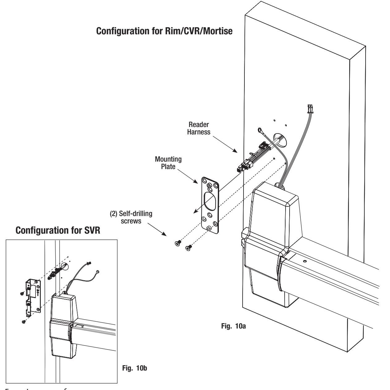
10. Install Mounting Plate:
- a. Feed reader harness through mounting plate (Fig. 10a, b).
- b. For Rim, CVR and Mortise:
Begin to secure mounting plate to inside door surface by fastening (2) Phillips flat head machine screws to lower right and left holes on mounting plate (Fig. 10a).
c. For SVR:
Secure mounting plate to inside door surface by fastening (2) Phillips flat head machine screws to holes on mounting plate (Fig. 10b)

7) Installation Instructions (Continued)
11. Connector Attachments:
- a. Connect 6-pin connector from exit device to 6-pin connector on reader harness (Fig. 11a, b).
- b. Connect 2-pin connector from exit device to 2-pin connector on reader harness (Fig. 11a, b).
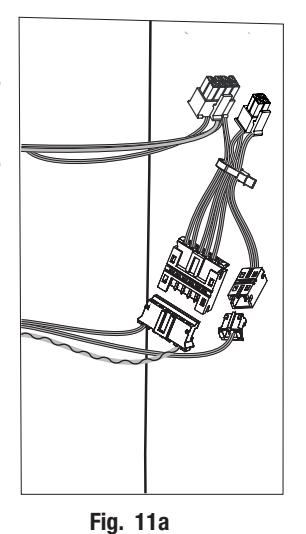
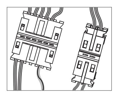
Fig. 11b
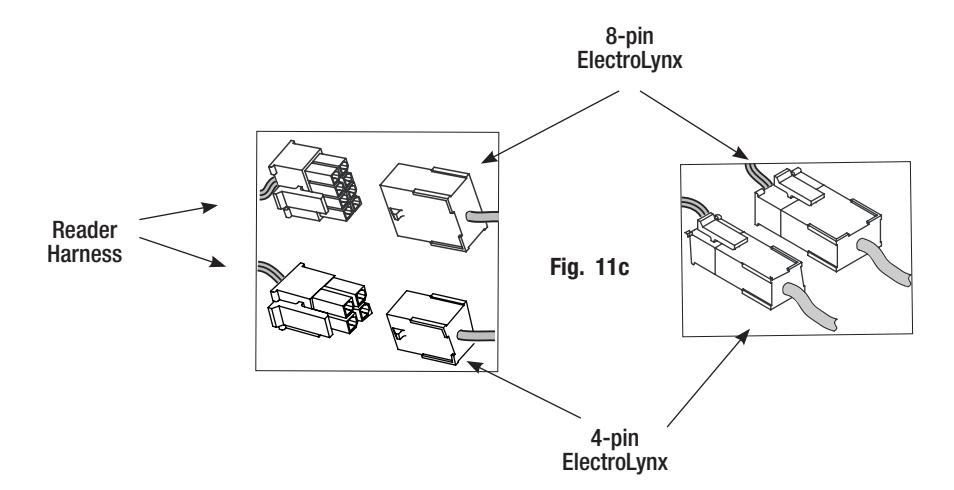
For the following refer to page 17 for ElectroLynx door harness and lock interface:
c. Connect ElectroLynx® 4- and 8-pin connectors from the door harness to (black) 4- and 8-pin connectors of the reader harness (Fig. 11c).
Carefully tuck connected harnesses into one-inch hole in door.
NOTE: Neatly fold the wires into the remaining space to prevent pinching wires when mounting inside escutcheon.
Do not offset connectors and be sure they are completely seated.

7) Installation Instructions (Continued)
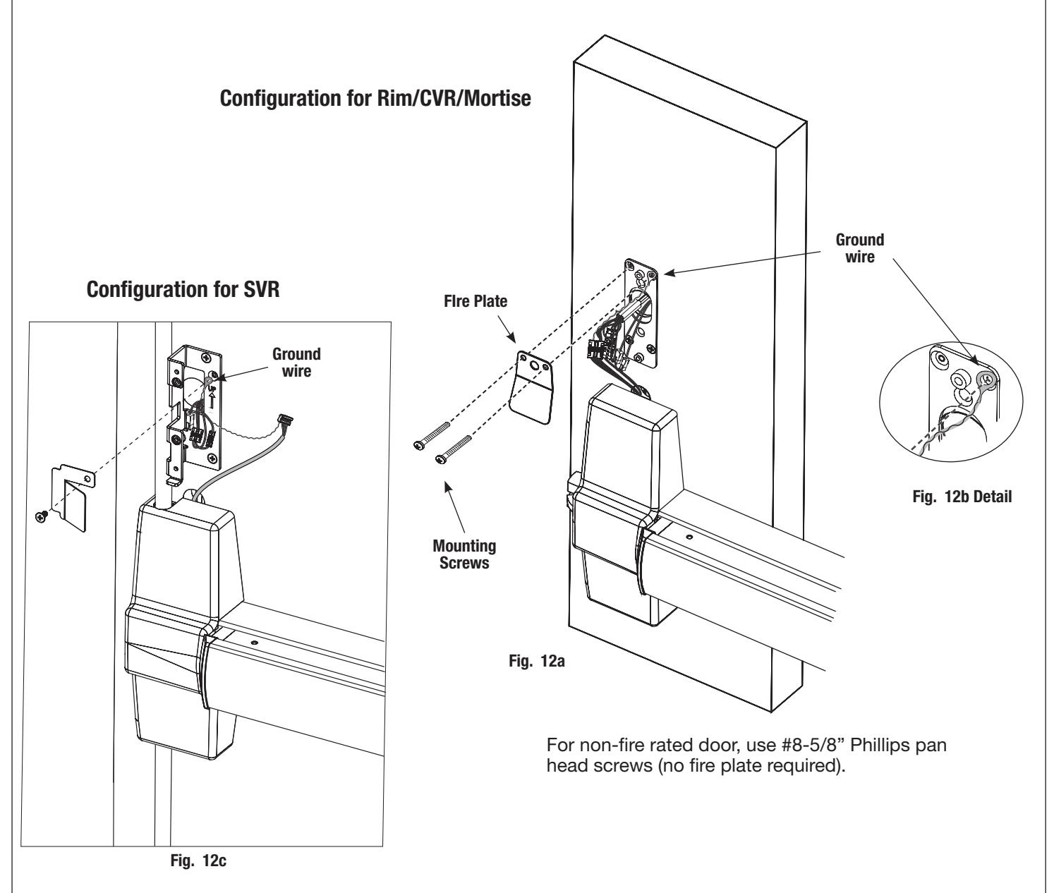
12. Install Mounting Plate and (optional) Fire plate:
- a. NOTE: For fire-rated doors only. Secure mounting plate and fire plate using (2) #8 1-1/4" Phillips pan head self-drilling screws provided (Fig. 12a). Ensure wires from reader are properly routed under flap of fire plate.
- b. Secure mounting plate using (2) remaining Phillips flat head self-drilling screws provided. Ensure wires from reader are properly routed under flap of fire plate.
- c. Place ground wire eyelet between upper right mounting plate hole and screw when securing mounting plate (and fire plate if used) to door (Fig. 12a, b).

7) Installation Instructions (Continued)
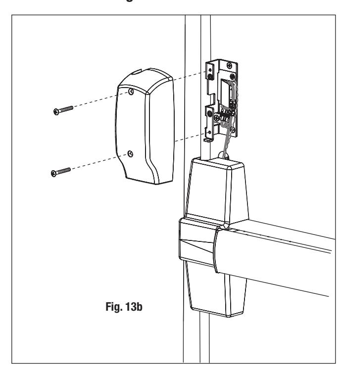
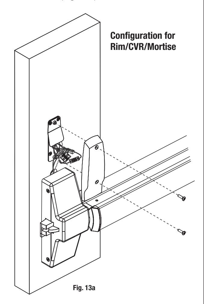
13. Install Inside Escutcheon:
Check electrical connections.
- a. Feed excess ElectroLynx® wire harness back into door.
- b. Feed excess trim and exit device harnesses under head cover.
- c. Install inside escutcheon using (2) #8-32 x 5/8" oval head screws (Fig. 13a).
Note: Be careful not to pinch wires between escutcheon and door surface.
CAUTION:
• Neatly fold wires onto themselves and into the remaining space to prevent pinching wires when mounting escutcheon.
Configuration for SVR
8) MELR Exit Device Configuration and Operational Check
Configuration Check
- Do not install the end cap until electrical operation is verified in order to confirm LED signaling.
- Do not discard the end cap and hardware.
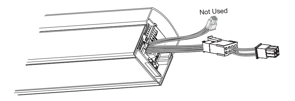
- a. Locate controller at end of rail (Fig. 12A).
- b. Ensure 'Power Mode' is set to ON as shown in Detail 12B.
NOTE: For more information, refer to FM434A MELR Exit Devices Installation & Wiring Instructions.
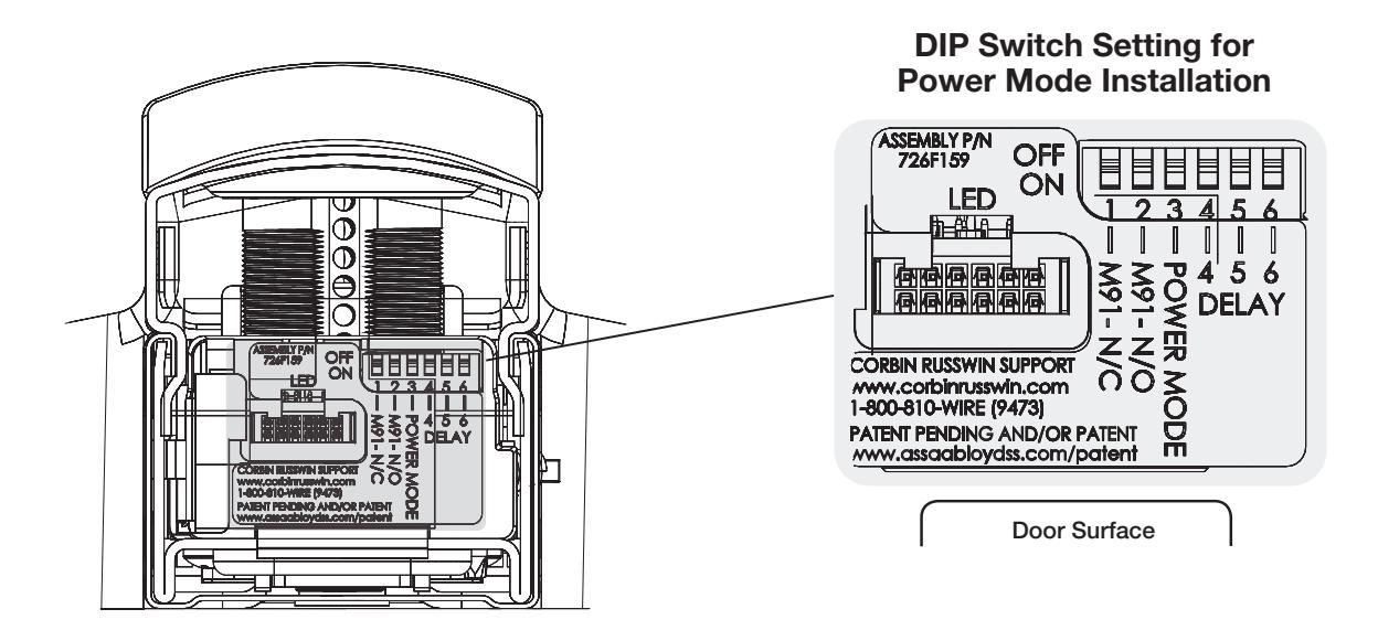
>> Reference Section 5 - Wiring Diagrams for wiring device to EAC panel <<

9) Door Postion Switch Installation
-
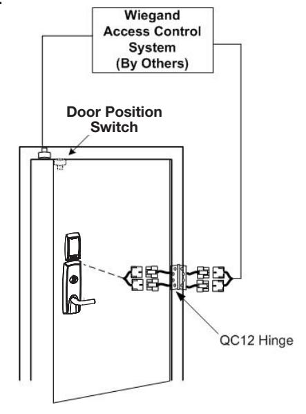
a. Install Door Position Switch supplied with product:
- Drill 1" hole in door for magnet
- Drill 1" hole in frame for switch
- b. Wire to ElectroLynx® frame harness as shown in wiring diagram on previous page. Door Position
10) Operational Check
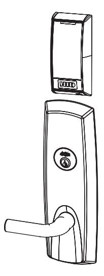
- a. Insert key into cylinder and rotate.
- b. With key rotated turn lever and check that latch retracts.
- c. Check that push bar fully retracts the latch.
- d. Close door: Ensure latch fully extends into strike and does not bind.
Note: For fail safe trim cylinder will have to be tested after wiring is complete and power is turned on.

10) Operational Check (Continued)
NOTE: Ensure LED operates as configured*:
• LED remains green when panel asserts GREEN_LED signal
*For configurations with GREEN_LED override enabled (Alternate Indicator Configuration); see Application Diagram #2 in Section 6.
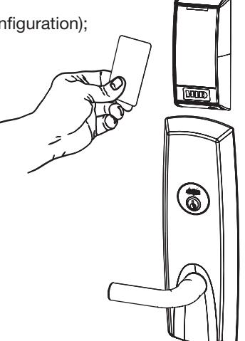
Note: Once electrical wiring has been successfully completed according to proper application, perform the following:
- a. Turn power ON.
- b. Verify LED located on reader is ON (Red or Green) depending on reader configuration
- c. Present valid credential and verify LED and sounder activity.
- d. Verify valid card read at EAC Panel.
- e. Verify system operation functions; i.e., when valid credential is presented to reader the door unlocks.
Wiegand Test Unit
The ASSA ABLOY Wiegand Test Unit verifies your installation in the field*. The test unit checks for proper wiring, card reader data integrity, lock functionality including lock/unlock, door position status, and request-to-exit (REX) status.
In addition, this tool provides product demonstration abilities to highlight the product's features and capabilities.
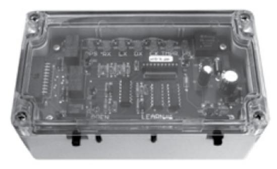
*For directions on use, see operating instructions provided with unit.
| Feature | WT1 | WT2 |
|---|---|---|
|
12 or 24VDC solenoid lock vol
tage adjustable |
X | X |
|
Operates as Fail Safe or Fail
Secure |
X | X |
|
"Learn" mode allows testing of
specific cards without program ming at panel level |
X | X |
|
Card reader data integrity is vali
dated at test unit |
X | X |
|
Displays detailed Wiegand data,
including hexadecimal string and total bits received |
X | |
|
Displays measured end-of-line
resistor values (if applicable) |
X |


Corbin Russwin 225 Episcopal Road Berlin, CT 06037 Phone: 800-543-3658 Fax: 800-447-6714 corbinrusswin.com
Copyright © 2020, ASSA ABLOY Access and Egress Hardware Group, Inc. All rights reserved. Reproduction in whole or in part without the express written permission of ASSA ABLOY Access and Egress Hardware Group, Inc. is prohibited.
HID, the HID logo, iCLASS SE, iCLASS, and Edge are trademarks or registered trademarks of HID Global in the U.S. and/or other countries. All other trademarks, service marks, and product or service names are trademarks or registered trademarks of their repsective owners.
For installation assistance contact Corbin Russwin 1-800-810-WIRE (9473) • techsupport.corbinrusswin@assaabloy.com FM385 06/20