Corbin Russwin Premium Delayed Egress for PED4000 and PED5000 Series Narrow and Wide Stile Mortise, Rim, CVR, SV…_FM574
Open the original PDF document
View PDF

PED4000 D, PED5000 D Series Exit Device
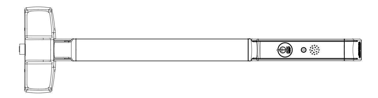
Available on the following devices: Rim Mortise Concealed Vertical Rod *Surface Vertical Rod
*Rod Guards Required (made by other manufacturers)
FM574 01/23
PED4000 D, PED5000 D Series Exit Device
Installation Instructions

| TOC | Table of Contents | |
|---|---|---|
| 1 | Panic and Fire Rated Devices 4 | |
| a | Checklist 4 | |
| b | Required Components 4 | |
| c | Optional Components 4 | |
| d | Electrical Specifications 4 | |
| 2 | Insert and PC Board Assembly 5 | |
| 3 | DIP Switch Settings 6 | |
| 4 | Device Mounting 8 | |
| 5 | Wire Routing | 10 |
| 6 | Installation of Insert Asssembly to Device | 21 |
| 7 | Harness Wiring Reconfiguration | 22 |
| 8 | Input/Output Connector Designations | 23 |
| 9 | ElectroLynx System | 26 |
| 10 | ElectroLynx Wiring Options Overview with QC12 Hinge | 27 |
| 11 | System Wiring Examples ElectroLynx QC8 Hinge | 28 |
| 12 | System Wiring Examples ElectroLynx QC12 Hinge | 30 |
| 13 | Field Wiring Door Prep | 32 |
| 14 | Operating Instructions | 33 |
| 15 | Additional Options Non ElectroLynx Wiring | 34 |
PED4000 D, PED5000 D Series Exit Device
Installation Instructions

| TOC | Table of Contents |
|---|---|
| 16 |
BOCA 15 Second Delay BC-59_ & BOCA 30 Second Delay BC-59
34 |
| 17 |
NFPA 101 Requirements: 30 Second Delay BC-59_ Suffix
34 |
| 18 |
Troubleshooting
35 |
WARNING
This product can expose you to lead which is known to the state of California to cause cancer and birth defects or other reproductive harm. For more information go to www.P65warnings.ca.gov.
NOTE:
• Wiring method must be in accordance with CSA C22.1, Canadian Electrical Code, Part I, Safety Standard for Electrical Installations, Section 32; and CAN/ULC-S524 Installation of Fire Alarm Systems.

Caution: Do not change factory applied finishes.
PED4000 D, PED5000 D Series Exit Device
Installation Instructions

Panic and Fire Rated Devices
a
Checklist
- 1. Check device for shipping damage prior to installation and make sure all parts are on hand.
- Identify options provided with device.
- Identify model, type and hand of trim if applicable (see exit device and trim instructions for reversing hands).
- Contact hardware supplier if device is damaged or missing parts.
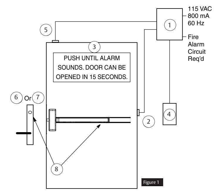
Required Components (Numbered list correlates with numbers in Figure 1)
- 24VDC UL Listed Regulated and Filtered Power Supply with Fire Alarm Interface (recommend Securitron BPS 24-1 or 24-2 (UL294 Listed), depending on requirements). Power supply is NOT to be used in UL603 Burglar Alarm System.
- 2. Power transfer UL or ULC listed (8 or 12 wire depending on system) ElectroLynx OC8 or OC12, Securitron (EPT) or equivalent.
- 3. Sign (MUST BE INSTALLED ON DOOR ABOVE DEVICE).
NOTE: The delayed egress system is to be installed in accordance with NFPA 101.
Optional Components (Numbered list correlates with numbers in Figure 1)
- Remote Annunciator
- Door Position Switch (DPS)
- 6. Standard Trim
- 7. Electrified Trim
- Device and Trim Cylinder
d
Electrical Specifications*
- Input Voltage: 24VDC +/- 15% (20.4 27.6VDC) regulated/filtered
-
Power Consumption @ 24VDC:
- 60 70 mA (typical) Disarmed
- 280 -340 mA (typical) Armed
- 320 830 mA (typical) Delayed Egress Initiated
- 70 90 mA (typical when arming)
- Output Relays: Form C, 1 Amp 24VDC
- Operating Temp: -40°C to 66°C (-40°F to 150.8°F)
*Follow Local Electrical Codes for Wiring. NOTE: Components shown do not reflect all possible applications. Refer to other system wiring diagrams within this manual. Consult manufacturer for special applications.
PED4000 D, PED5000 D Series Exit Device
Installation Instructions

2 Insert and P.C. Board Assembly
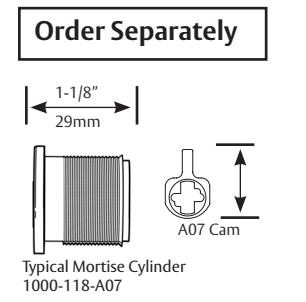
Cylinder and Collars
- Use standard 1-1/8" mortise cylinder with A07 cam, no collar. Corbin Russwin #1000-118-A02 collar is not required.
- Use Corbin Russwin spacer 370F29 for optional 1-1/4" long cylinder.
- Use Corbin Russwin spacer 370F31 for optional 1-1/2" long cylinder.
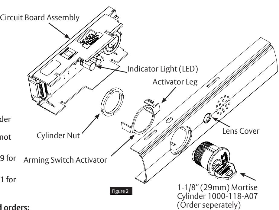
Assembly steps for non-factory-keyed orders:
- 1. Insert cylinder through the cylinder support piece in the rail insert with keyway horizontal and toward the closest end of the rail insert.
- 2. Slide arming switch activator over cylinder and onto the cylinder support piece. Notch in arming switch activator keys over the stop feature in cylinder support.
- 3. Secure parts in place with cylinder nut. Be certain arming switch activator sits around flange in the cylinder support piece to allow rotation of activator.
- 4. Insert circuit board assembly into rail insert over cylinder and switch activator. Ensure the fingers of the arming switch activator straddle the switch mounted to the circuit board. Press down until it snaps into all four slots in the rail insert.
- 5. Verify assembly by rotating key counter-clockwise and clockwise. Key should move freely and arming switch should trip for both rotation directions. If key does not rotate freely, verify arming switch activator is properly seated on cylinder support piece.
FM574 01/23
PED4000 D, PED5000 D Series Exit Device
Installation Instructions

2 Insert and P.C. Board Assembly, continued
NOTES:
- Factory keyed orders will be shipped assembled.
- Prior to insert assembly, device must be cut to proper length to prevent damage to circuit board 36" device cannot be field cut. A maximum of 6" can be cut from a 48" device.
S2 1 Nuisance Audible 2 Nuisance Delay 8 DPS Bypass 3 Nuisance Delay 4 Reset Delay 5 Reset Delay 6 Armed LED Color 7 RAC 3 DIP Switch Settings S2-1: Nuisance Audible may be selected ON (default) or OFF PCBA DIP SWITCH VIEW S2-8: Switch must be set ON (default) to Bypass when an external Door Position Switch (DPS) is NOT used, and OFF when an external DPS is used. S2-2 and S2-3: Nuisance Delay time may be selected 0 (Immediate), 1 (default), 2 or 3 seconds S2-4 and S2-5: Reset Delay time may be selected 5, 10 (default), 20 or 40 seconds S2-6: Cover Armed LED Color is Red (default) when ON and Green when OFF S2-7: Re-arm After Closing (RAC)* (see below) S2 Dip Switch - Default Settings
| S2 Dip Switch - Default Settings | ||||||||
|---|---|---|---|---|---|---|---|---|
| S2 Dip SW | 1 | 2 | 3 | 4 | 5 | 6 | 7* | 8 |
| OFF (UP) | OFF | OFF | OFF | |||||
| ON (DOWN) | ON | ON | ON | ON | ON | |||
PED4000 D, PED5000 D Series Exit Device
Installation Instructions

3 DIP Switch Settings, continued
| Nuisance Delay (seconds) | ||||||
|---|---|---|---|---|---|---|
| 0 | 1 | 2 | 3 | |||
| S2-2 | OFF | OFF | ON | ON | ||
| S2-3 | OFF | ON | OFF | ON | ||
| Reset Delay (seconds) | ||||||
| 5 | 10 | 20 | 40 | |||
| S2-4 | OFF | OFF | ON | ON | ||
| S2-5 | OFF | ON | OFF | ON | ||
| S2-6 | OFF | Cover Armed LED Color is Green |
|---|---|---|
| ON | Cover Armed LED Color is Red (default) | |
|
S2-7
OFF* |
Momentary egress mode 5, 10, 20 or 40 seconds. Device will immediately
Rearm After Closing (RAC) door, if closed before selected time expires or it will enter alarm mode, if time expires with door open (default). See other details* |
|
| ON** |
40 seconds momentary egress mode is extended indefinitely, if the door
is left open. Then the device immediately Rearms after Closing (RAC) door. See other details** |
|
|
S2-8
OFF External DPS is wired to device |
||
| ON | DPS Bypass, external DPS is NOT wired to device (default) | |
Default
*With S2-7 OFF (S2-4 and S2-5 set for 5, 10, 20 or 40sec), if door/DPS is open after selected time the alarm will sound. Close door to reset and rearm device using cylinder key or remote reset signal.
**S2-7: When an external DPS is used and switch S2-7 ON, and 40 second reset delay (S2-4 and S2-5) are set ON, after activation of momentary egress by cylinder key switch or external remote reset signal, if the Door/DPS is open beyond 40sec the device will remain in momentary egress mode indefinitely and shall not enter alarm mode; then once the Door/DPS is closed it will rearm immediately.
If door/DPS is opened then closed before selected time expires, the device will rearm immediately.
If DPS is not used, is bypassed with S2-8 ON, the door will rearm immediately after 5, 10, 20 or 40 sec whether the door is open or closed, with either S2-7 ON or OFF.
Ensure eight S2 Dip Switches are set per application before moving on to the next page of instructions.
PED4000 D, PED5000 D Series Exit Device
Installation Instructions

4 Device Mounting
- 1. Refer to installation instructions included with device and trim for complete door and frame preparations. Refer to template for wire access hole location.
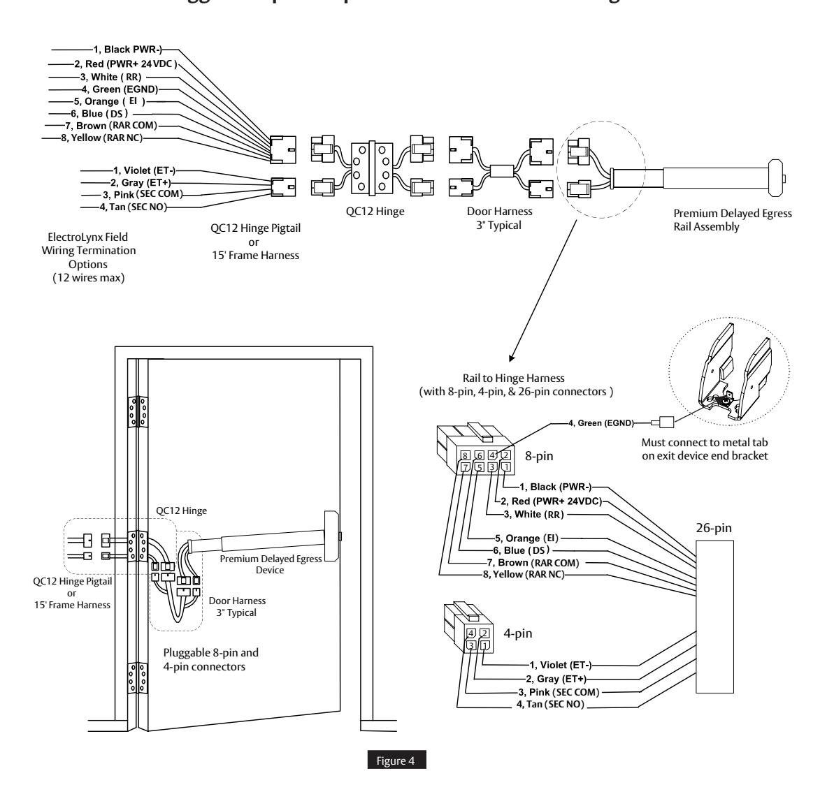
- 2. Feed wires from power transfer through wire access hole in door. (Figure 4)
ElectroLynx System Default Wiring Options for DEED QC12 Hinge (12 wires) Pluggable 8-pin & 4-pin connectors. Default wiring shown.
NOTES:
- Wires must be protected from abrasion.
- For use with Class II circuits only.
PED4000 D, PED5000 D Series Exit Device
Installation Instructions

4 Device Mounting, continued
Note: For additional instructions on hardware install, refer to mechanical instructions.
- 3 When required, mount outside trim to door ( see trim installation instructions ).
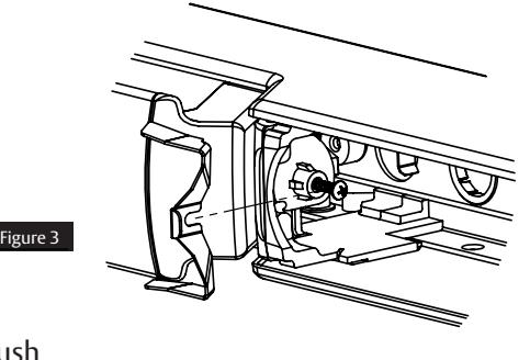
- 4. Unthread screw and remove dogging slope bracket (Figure 3).
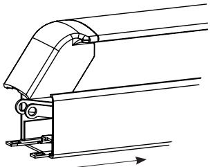
5. Pull the mount rail cover back to expose front end of the carrier/push assembly (Figure 4).
6. Install chassis on door. Leave chassis screws loose. Insert rail onto chassis. Pin bracket to slot in chassis lift arm
(Figure 5).
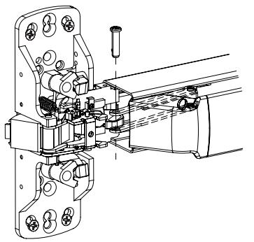
Figure 4
Figure 5
7. Slide the mount rail back to the front and replace the dogging slope bracket and screw (Figure 6).
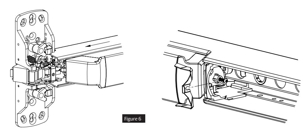
7. Do not install end cap until device has been wired and tested for operation (See wiring diagrams).
FM574 01/23
PED4000 D, PED5000 D Series Exit Device
Installation Instructions

PED4000 D, PED5000 D Series Exit Device
Installation Instructions

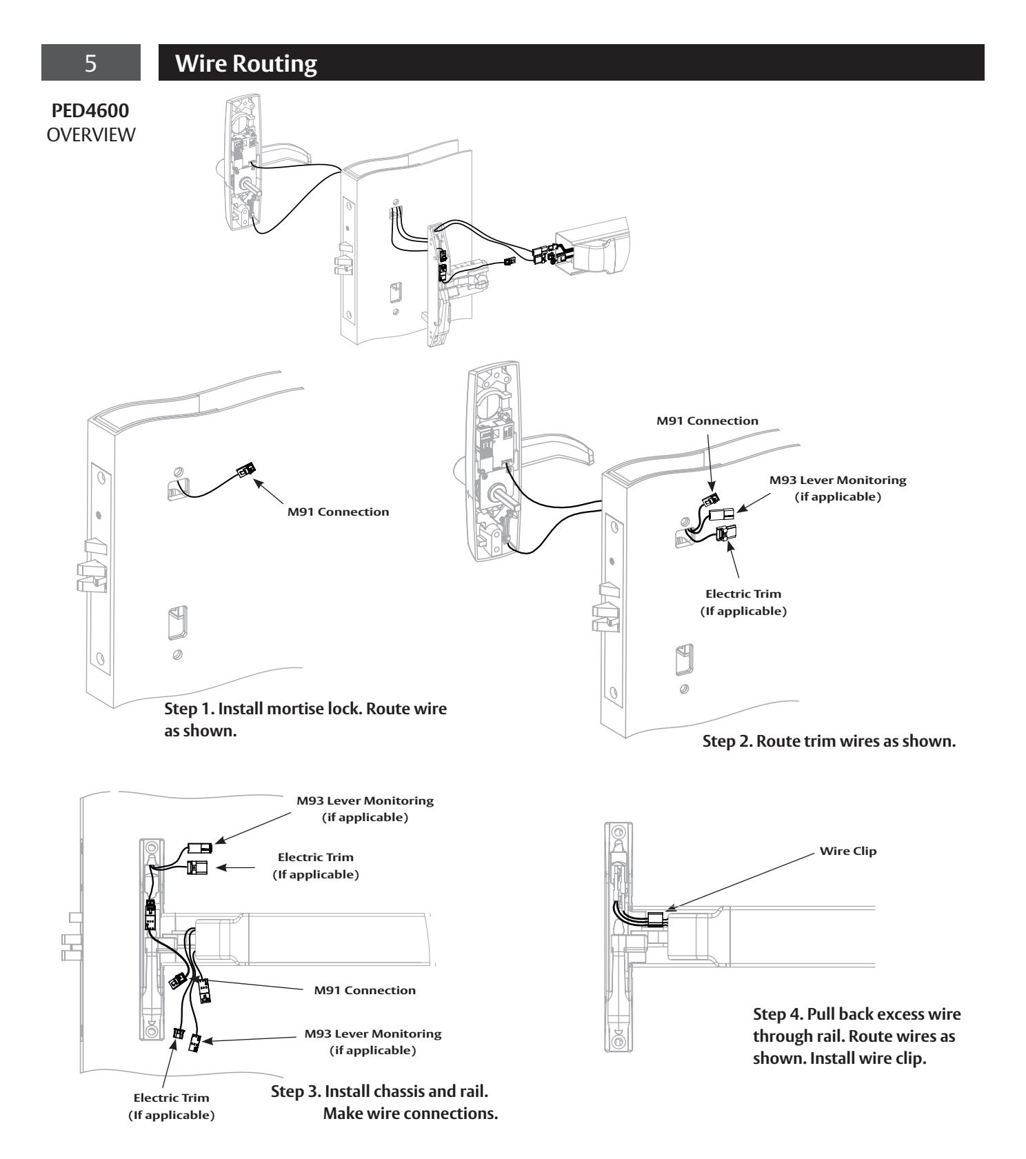
5 Wire Routing - continued
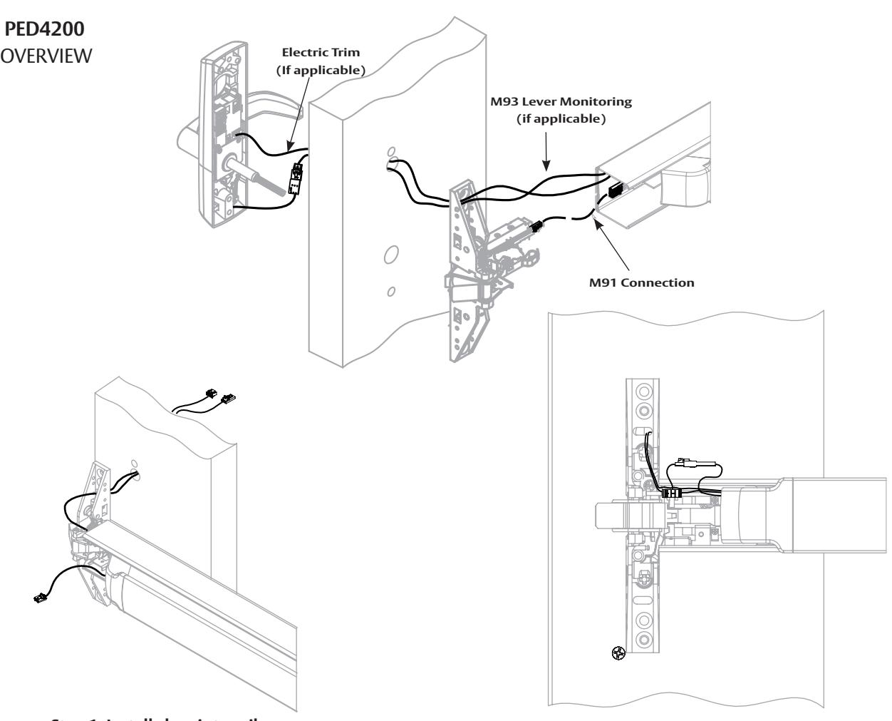
PED4800 OVERVIEW
PED4000 D, PED5000 D Series Exit Device
Installation Instructions

5 Wire Routing - continued
PED4800
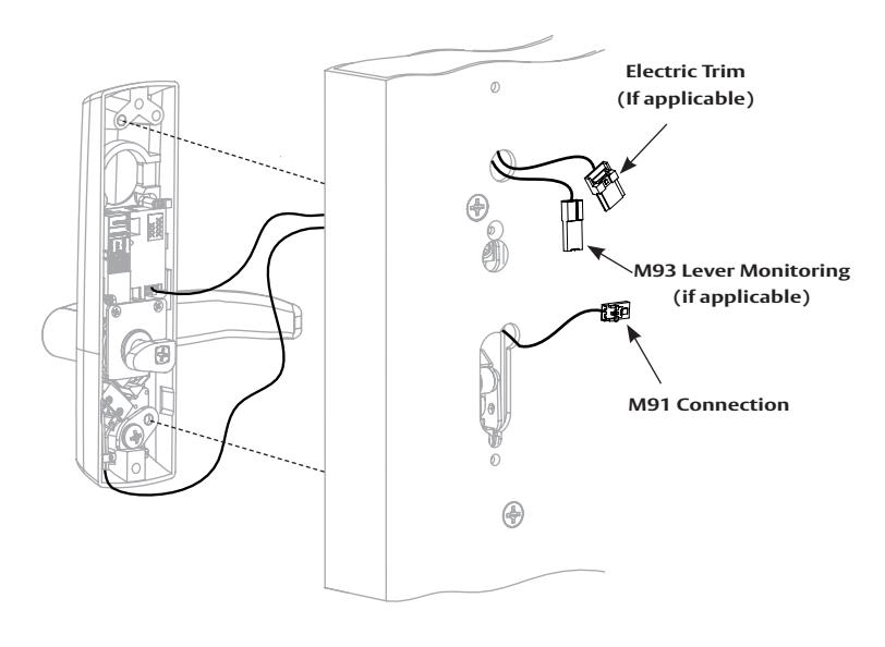
Step 1. Route wires as shown and secure trim to door.
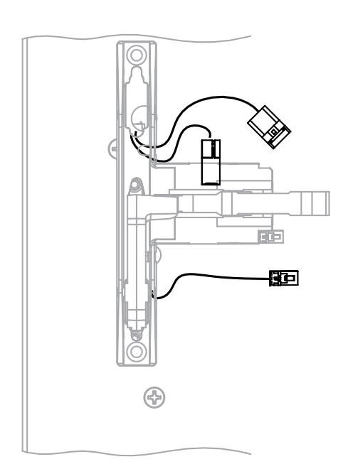
Step 2. Route wires through chassis as shown and secure chassis to door.
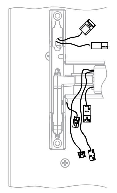
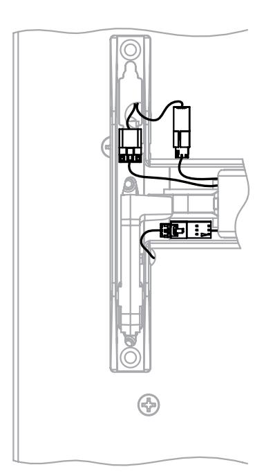
Step 3. Install rail. Step 4. Make wire connections.
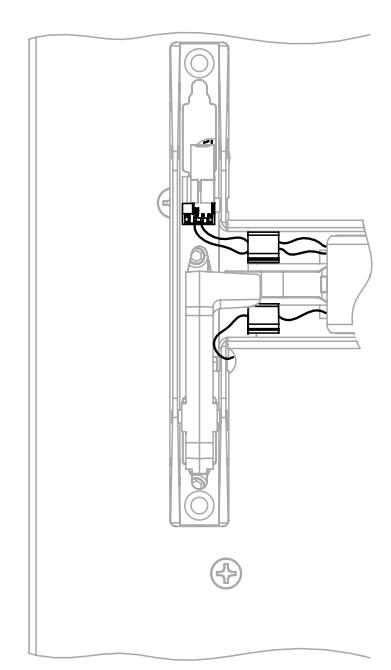
Step 5. Pull back excess wire through rail. Route wires as shown. Install wire clips.
FM574 01/23
PED4000 D, PED5000 D Series Exit Device
Installation Instructions

5 Wire Routing - continued
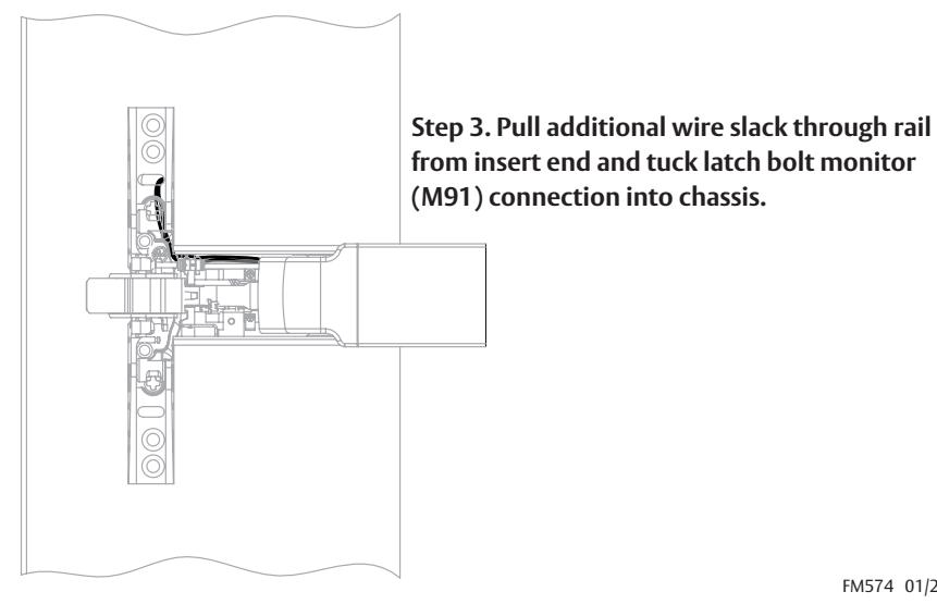
Step 2. Secure trim. Make M91 connection. Step 1. Install chassis to rail. Route wires through door as shown.
FM574 01/23
PED4000 D, PED5000 D Series Exit Device
Installation Instructions

5 Wire Routing - continued
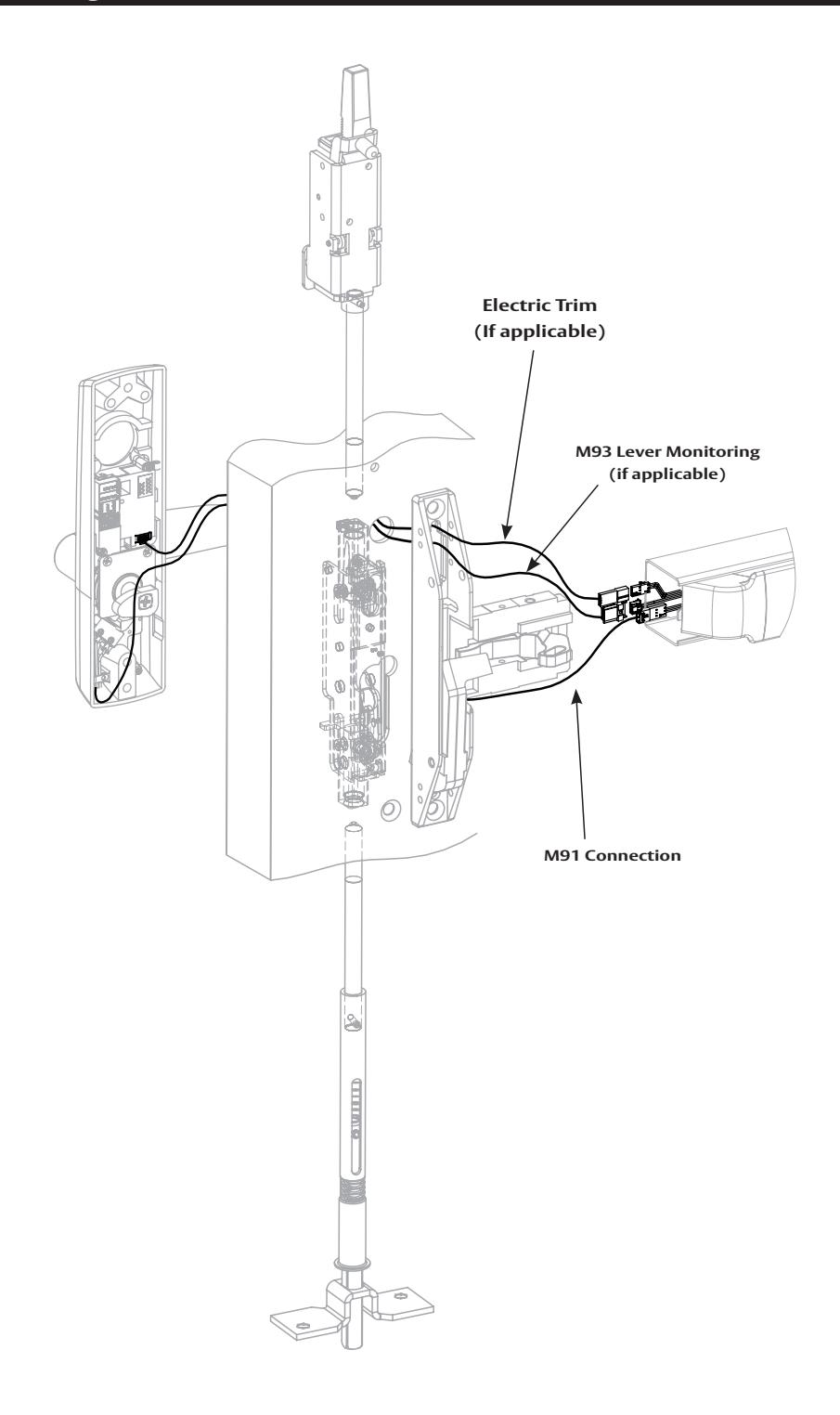
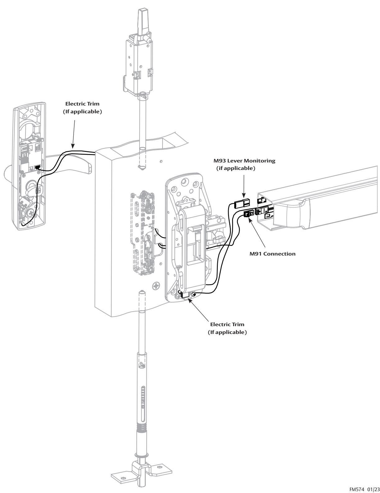
PED5800 OVERVIEW
For installation assistance contact Corbin Russwin 1-800-543-3658 • techsupport.corbinrusswin@assaabloy.com
14
PED4000 D, PED5000 D Series Exit Device
Installation Instructions

5 Wire Routing - continued
PED5800
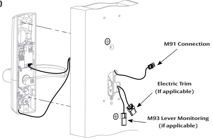
Step 1. Route wires as shown and secure trim to door.
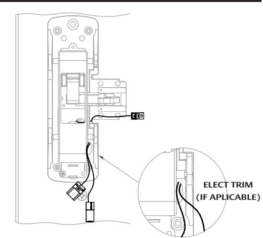
Step 2. Install chassis (Section 4) and route wires through chassis as shown.
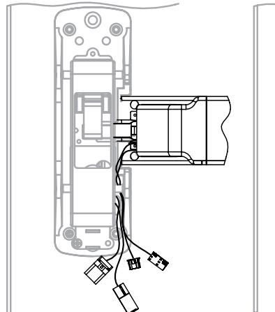
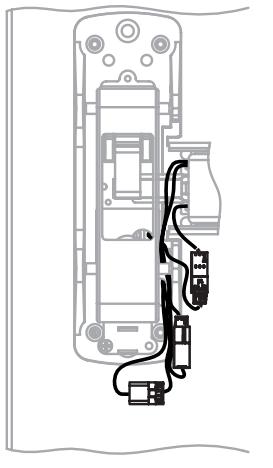
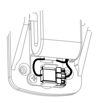
Step 3. Install rail. Step 4. Make wire connections. Step 5. Snap trim jumper to clip and route excess wire as shown.
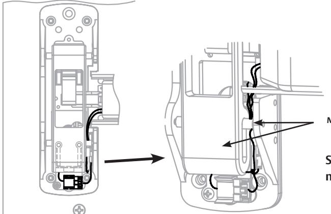
Main Slide & Roller
Step 6. Tuck wire connections along side of main slide. Pull back excess wire through rail.
PED4000 D, PED5000 D Series Exit Device
Installation Instructions

5 Wire Routing - continued
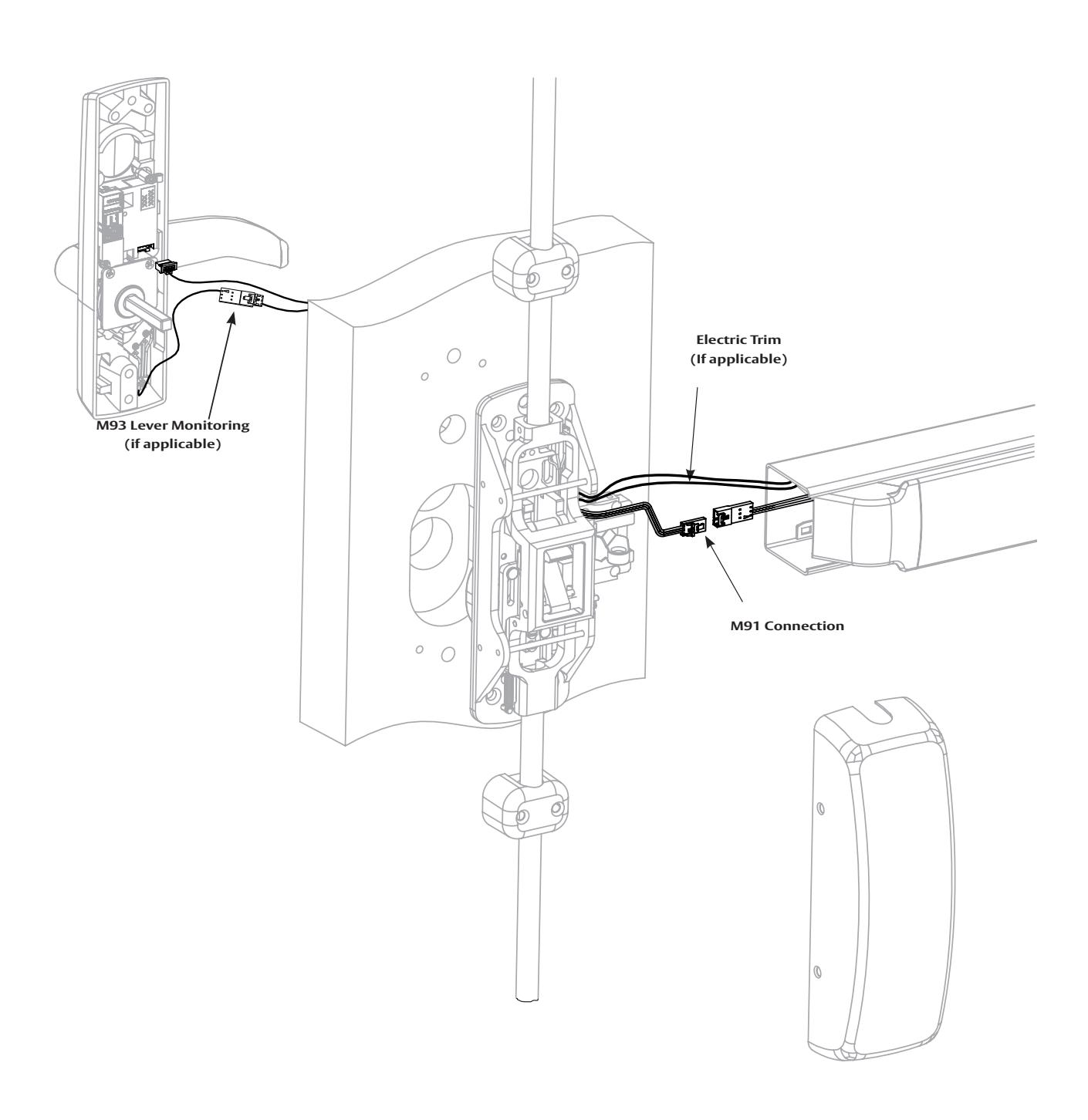
PED5400 OVERVIEW
PED4000 D, PED5000 D Series Exit Device
Installation Instructions

5 Wire Routing - continued
PED5400
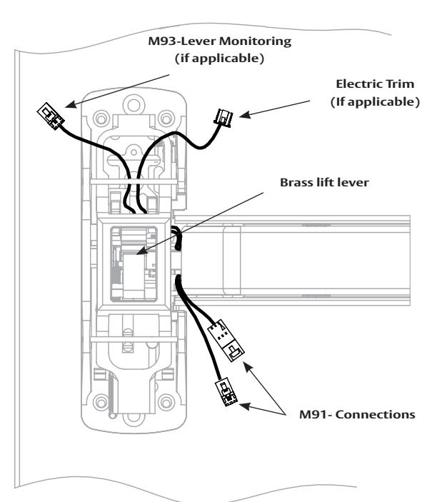
Step 1. Install chassis and rail (Section 4). Route trim wires from rail under brass lift lever as shown.
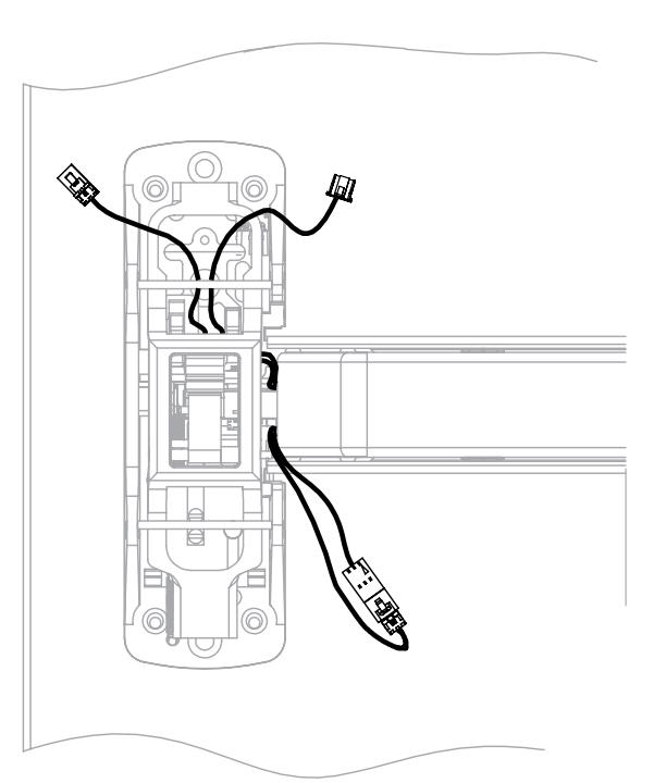
Step 2. Make M91- connection.
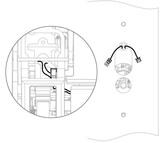
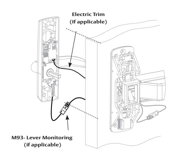
Step 3. Route trim wires through chassis and door as shown. Step 4. Make trim wire connections and secure trim to door. Pull back excess wire through rail.
PED4000 D, PED5000 D Series Exit Device
Installation Instructions

5 Wire Routing - continued
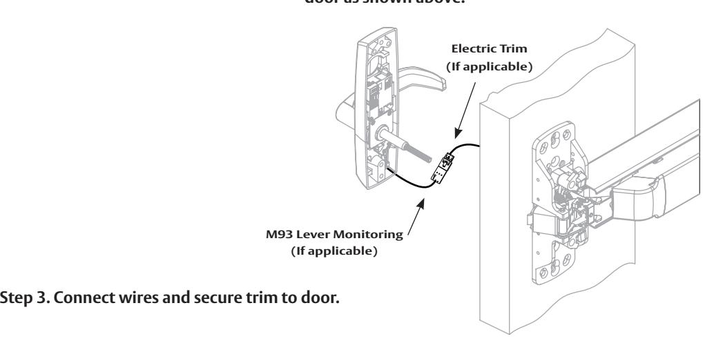
PED5200
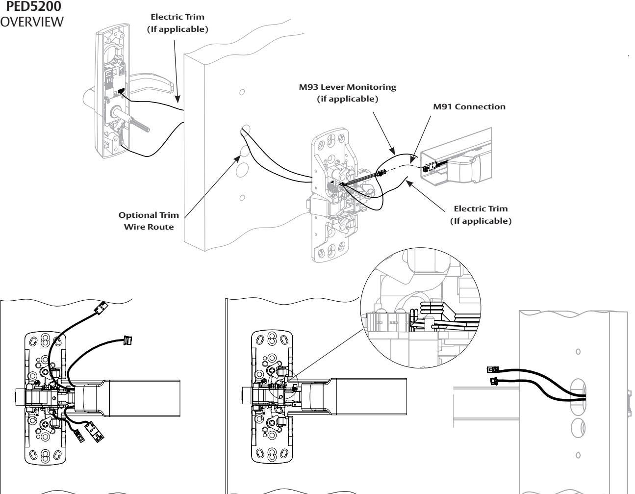
Step 1. Install chassis and rail. Step 2. Route trim wires through chassis and door as shown above.
Step 2A. Additional view
FM574 01/23
PED4000 D, PED5000 D Series Exit Device
Installation Instructions

5 Wire Routing - continued
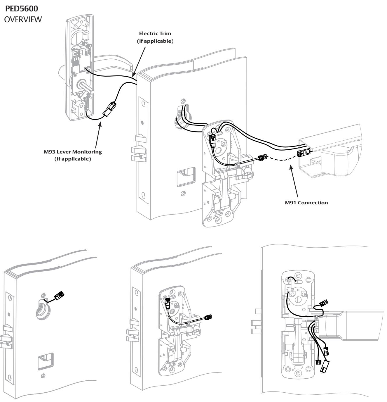
wire as shown.
Step 2. Install chassis and connect M91 jumper at chassis. Step 1. Install mortise lock. Route Step 3. Install rail to chassis.
PED4000 D, PED5000 D Series Exit Device
Installation Instructions

5 Wire Routing - continued
PED5600
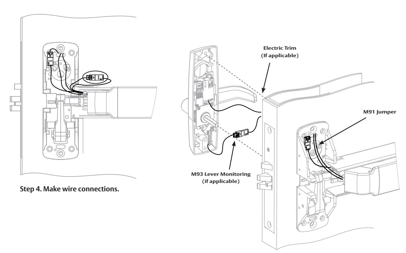
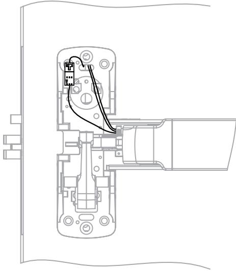
Step 6. Pull back excess wire through rail. Step 6. Pull back excess wire through rail.
Step 5. Secure trim to door.
PED4000 D, PED5000 D Series Exit Device
Installation Instructions

6 Installation of Insert Assembly to Device
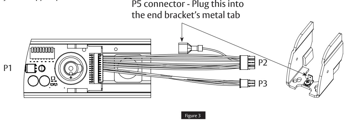
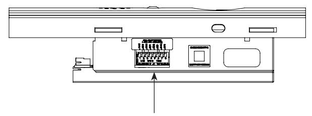
- 1. The Dip Switches are on the side of the assembly. Ensure eight S2 Dip Switches are set for application (see Section 2).
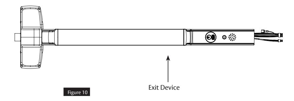
- 2. Slide insert assembly into device, making sure not to pinch or crimp wires.
- 3. Connect device lock assembly harness to connector J1. Place wire connectors and excess wire between insert and P.C. board. (Figure 3, Device End View)
- 4. Check all connections before proceeding.
- 5. Proceed to device mounting (see packed instructions).

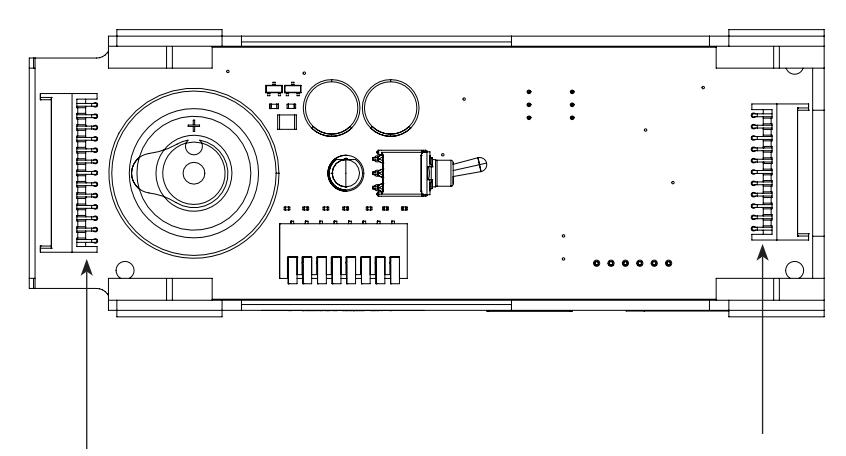
Silicone dielectric grease is applied at the factory onto J200 and J201 connectors, terminals, and wires here.
For use on exterior doors
PED4000 D, PED5000 D Series Exit Device
Installation Instructions

7 Harness Wiring Reconfiguration
PED Series Exits PCBA to QC12 Hinge Side Harness
26-pin Connector to 8 & 4-pin ELynx connectors
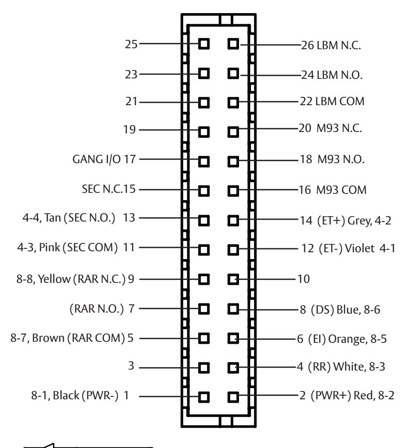
| PED Series Exits | ||||||
|---|---|---|---|---|---|---|
| ElectroLynx QC12 | ||||||
| Factory Default Ship Configuration | ||||||
| 26-1 | PWR- | Black | 8-1 | |||
| 26-2 | PWR+ | Red | 8-2 | |||
| (24VDC) | ||||||
| 26-4 | RR | White | 8-3 | |||
| Quick Conn | EGND | Green | 8-4 | |||
| 26-6 | EI | Orange | 8-5 | |||
| 26-8 | DS | Blue | 8-6 | |||
| 26-5 | RAR COM | Brown | 8-7 | |||
| 26-9 | RAR N.C. | Yellow | 8-8 | |||
| 26-12 | ET- | Violet | 4-1 | |||
| 26-14 | ET+ | Grey | 4-2 | |||
| 26-11 | SEC COM | Pink | 4-3 | |||
| 26-13 | SEC N.O. | Tan | 4-4 | |||
| 26-7 | RAR N.O. | No wire | ||||
| 26-15 | SEC N.C. | No wire | ||||
| 26-16 | M93-COM | No wire | ||||
| 26-17 | GANG I/O | No wire | ||||
| 26-18 | M93- N.O. | No wire | ||||
| 26-20 | M93- N.C. | No wire | ||||
| 26-22 | LBM COM | No wire | ||||
| 26-24 | LBM N.O. | No wire | ||||
| 26-26 | LBM N.C. | No wire | ||||
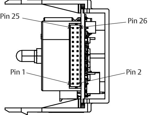
Legend PED Series Exits
M91 - Latch Monitor Switch (Form C) in chassis
M92 - Push Bar Switch (Form C) in rail
EGND - Earth Ground connection to metal rail, required
ET - Electrified Exit Trim (Fail Safe or Fail Secure) Ecoflex 10 to 28VDC
M93 - ET Outside Lever Monitor Switch (Form C)
PED4000 D, PED5000 D Series Exit Device
Installation Instructions

8 Input and Output Connector Designations
|
Harness
Connector Pin Number* |
Circuit
Board Pin Number |
Input/
Output |
Harness
Wire Color |
Function |
|---|---|---|---|---|
| 8-2 | J200-2 | Input | Red | +24 VDC power |
| 8-1 | J200-1 | Input | Black | -Return |
| 8-3 | J200-4 | Input | White | Remote Reset |
| 8-5 | J200-6 | Input | Orange |
External inhibit - disarm unit
from i/s or o/s (key switch, card reader, keypad) |
| 8-6 | J200-8 | Input | Blue |
Door position sensor (Door
status/Monitor) |
|
Harness
Connector Pin Number* |
Circuit
Board Pin Number |
Input/
Output |
Harness
Wire Color |
Function |
|---|---|---|---|---|
| 8-4 | Chassis | Ground | Green | ESD (Earth Ground) |
| 8-7 | J200-5 | Output | Brown | Remote Alarm Relay (C.) |
| 8-8 | J200-9 | Output | Yellow | Remote Alarm Relay (N.C.) |
| 4-1 | J200-12 | Input | Violet | ET |
| 4-2 | J200-14 | Input | Grey | ET+ |
| 4-4 | J200-13 | Output | Tan | Secure Relay (N.O.) |
| 4-3 | J200-11 | Output | Pink | Secure Relay (C.) |
* Example: 8-2 is the 8-pin connector position #2. 4-3 is the 4-pin Connector position #3
NOTE:
Remote alarm relay shown in power "off" state. Power "on" relay energizes; contacts reverse state.
PED4000 D, PED5000 D Series Exit Device
Installation Instructions

8 Input and Output Connector Designations, Continued
|
Harness
Connector Pin Number* |
I/O Circuit
Board Pin Number |
Function |
|---|---|---|
| 8-2 | J200-2 |
+24 VDC Power Supply Input (+) - This input may be tied to the normally closed
contact of a building's fire alarm system. If the fire alarm is activated, this contact will open, voiding the15 second delay for egress. |
| 8-1 | J200-1 | Return - Power Supply -return (-) |
| 8-3 | J200-4 |
Remote Reset - This input may be tied to a momentary normally open contact
at a remote location to reset the device when in alarm. Additionally when the device is armed, this input may be used for momentary egress with the time per the dip switch settings. |
| NOTE: Previous Fire Alarm Input option has been replaced with Remote Reset. | ||
| 8-4 | Chassis Ground |
Chassis Ground - The chassis ground wire must terminate at earth ground of the
equipment power supply or the main power source. |
| 8-5 | J200-6 |
External inhibit Input - Used to provide remote override of the delayed egress
when in the armed condition. Most common external inhibits are: key switches, card readers, keypad, or remote control console. More than one external inhibit device must be wired in parallel |
| 8-6 | J200-8 |
Door position sensor - An external door status switch can be connected to the
DEED to provide additional security. If the door status switch is utilized, an irre versible alarm will sound if the door is forced open while the device is armed. Unit will not arm if door is not shut. Once the irreversible alarm sounds, it will have to be reset at the door. If the door status switch is not utilized, set DIP Switch S2-8 to the ON position. |
| 8-7 | J200-5 |
Remote Alarm Relay - A SPDT (Single Pole Double Throw) 1A, 24 VDC contact
relay is provided for external alarm indication. The contacts change state when the unit goes into an irreversible alarm or if the door is forced open while the |
| 8-8 | J200-9 |
device is armed. A door position sensor is required for monitoring a door forced
open condition. This contact can be utilized to drive a horn, lamp or other monitoring device. |
| 4-1 | J200-12 |
ET- and ET+ - Electrified Exit Trim (Fail Safe or Fail Secure) can be used for
authorized ingress (via card reader, keypad, and other switches). |
| 4-2 | J200-14 | |
| 4-3 | J200-11 |
SEC-C and SEC-NO: SPDT (Single Pole Double Throw) -1A, 24VDC relay. Secure
(SEC) relay changes state after 15 or 30 second delayed egress delay. |
| 4-4 | J200-13 |
PED4000 D, PED5000 D Series Exit Device
Installation Instructions

8 Input and Output Connector Designations, Continued
NOTE: ElectroLynx QC12 Hinge is required if Electrified ET, Secure (SEC) Relay and/or if any other additional nondefault wiring is required.
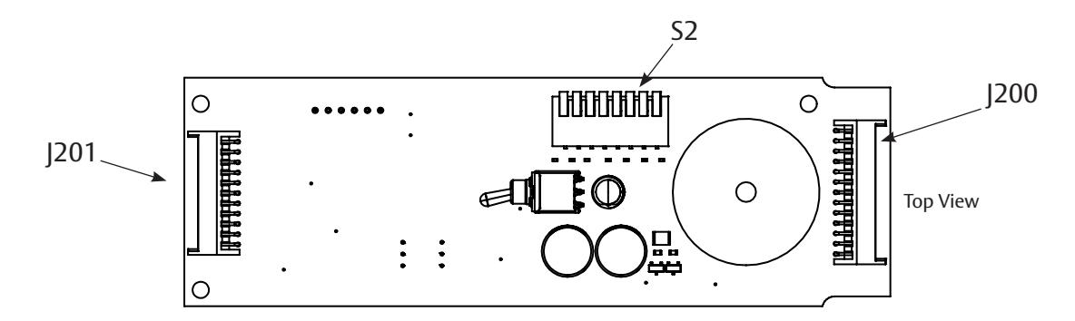
PED4000 D, PED5000 D Series Exit Device
Installation Instructions

9 ElectroLynx Connector System for All Electrical Installation
- 1. Mount exit device per instruction sheet provided.
- 2. Plug exit device connector into raceway connector in door. Feed through 1" (25mm) hole in door. Install rail mounting end clamp bracket with two (2) screws supplied. Install end cap.
-
3. Plug raceway connector from edge of door into electric hinge connector and feed wires back through door prep. Mount electric hinge to door.
- A. If wiring now, wire frame side wires, to wires on pigtail harness, on hinge as required by using connectors allowed by local code. Plug pigtail harness connector into electric hinge connector. Feed harness through frame prep and mount electric hinge.
- B. If wiring later, plug pigtail harness connector into electric hinge connector. Feed harness through frame prep and mount electric hinge.
Installation Notes:
- 1. Wiring to pigtail harness is per facility wiring requirement.
- 2. For an ElectroLynx system, go to function or monitor page(s) with your device.
- 3. Combinations of certain monitors can be used in each device. These instructions detail installation of each monitor separately.
ElectroLynx Connector System Notes:
System is designed to be installation friendly, with plug connectors from electric hinge through door to device. The only wiring required is loose wires on pigtail harness assembly on frame side of electric hinge (included with QC Hinge). Combinations of certain switches and monitors can be used.
The plug and receptacle connectors are designed to mate and lock together. Plug connectors into each other with locking mechanism aligned. Do NOT force connectors together any other way.
PED4000 D, PED5000 D Series Exit Device
Installation Instructions

10 ElectroLynx Wiring Options Overview with QC12 Hinge
- 1. Refer to installation instructions included with device and trim for complete door and frame preparations. Refer to template for wire access hole location.
- 2. Feed wires from power transfer through wire access hole in door. (Figure 4)
ElectroLynx System Default Wiring Options for DEED QC12 Hinge (12 wires) Pluggable 8-pin & 4-pin connectors. Default wiring shown.
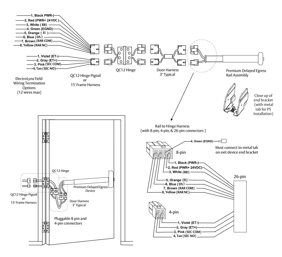
NOTES:
- Wires must be protected from abrasion.
- For use with Class II circuits only.
PED4000 D, PED5000 D Series Exit Device
Installation Instructions

11
System Wiring Examples ElectroLynx QC8 Hinge
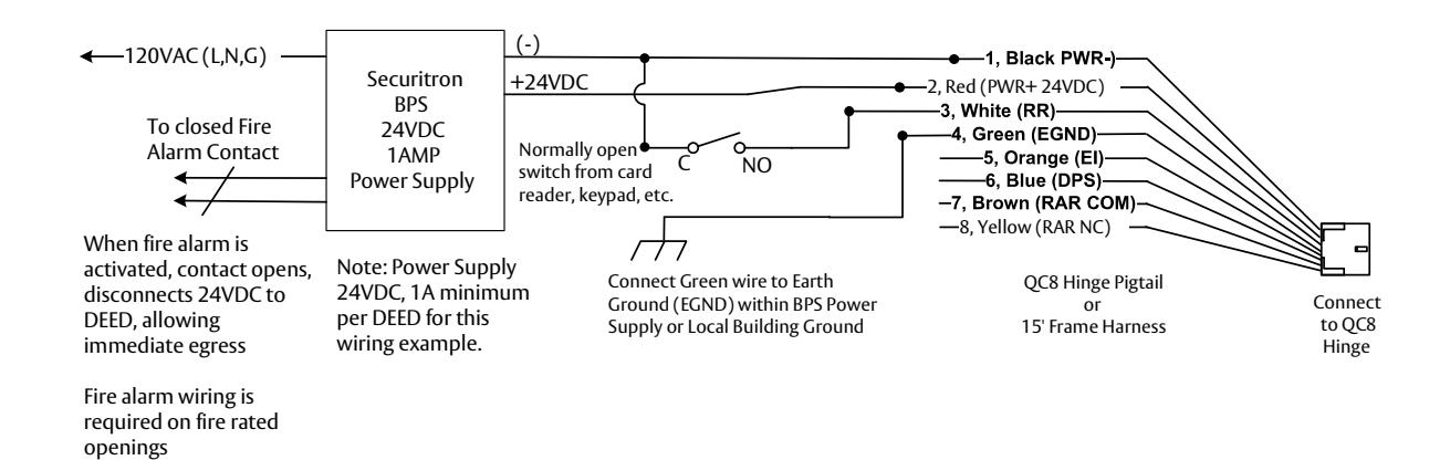
Delayed Egress System with Fire Alarm and Remote Reset with ElectroLynx QC8 Hinge
During a fire alarm condition, the fire alarm contact opens which removes power from Delayed Egress (rail) and allows immediate egress. Rail can be rearmed by momentary closure at the Remote Reset (RR) switch. When armed, a momentary RR signal will shunt rail for 5, 10, 20, or 40sec (for time set by reset delay dip switches) allowing egress for set time, then rail rearms automatically.
Closeup of end bracket (with metal tab for P5 Installation)
QC8 Hinge QC8 Hinge QC8 Hinge Premium Delayed Egress Exit Device (DEED) Door Harness 3" Typical ElectroLynx pluggable 8-pin and 4-pin connectors Only 8-pin connectors need to be plugged in
Wiring Notes:
- 1. Rail harness, door harness, electric hinge and pigtail/frame harness connector terminations and wire colors all match.
- 2. Wiring to remaining hinge pigtail wires is as required. Tape or cap off ends of unused pigtail wires (not shown) to ensure that they don't short to anything.
- 3. A fire alarm tie-in is required on fire rated openings.
- 4. Rail DPS bypass dip switch 8 must be set ON, which is default setting.
PED4000 D, PED5000 D Series Exit Device
Installation Instructions

11
System Wiring Examples ElectroLynx QC8 Hinge, Continued
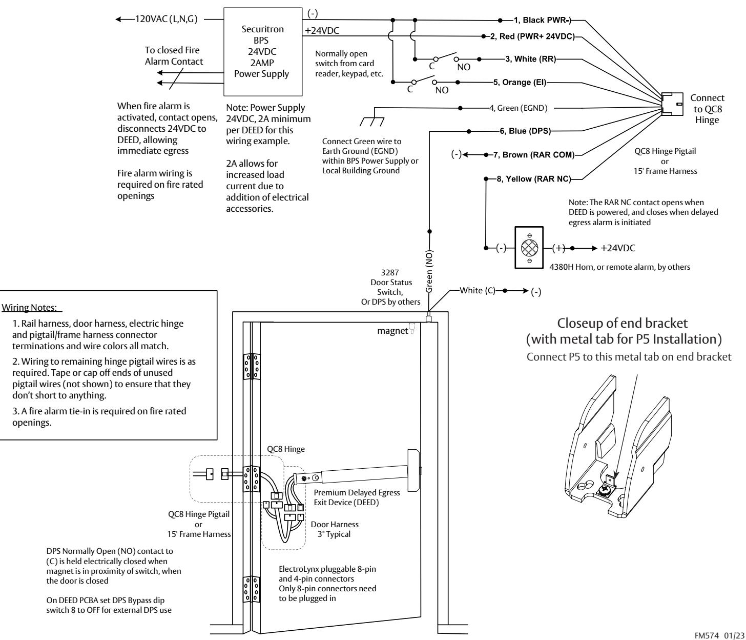
Delayed Egress System with Fire Alarm, Switch Controls, DPS, Horn with ElectroLynx QC8 Hinge
During a fire alarm condition, the fire alarm contact opens which removes power from DEED (rail) and allows immediate egress. For External Inhibit (EI) control, a valid code entry at the Inside keypad or valid card presentation at Inside card reader shunts the rail and allows egress for a time period programmable at the keypad.
For Remote Reset (RR) control, a valid code entry at the Inside keypad or valid card presentation at Inside card reader shunts the rail and allows egress for a time period programmable at the keypad plus the rail time set by the reset delay dip switch settings. RR also can be used to rearm rail from alarm condition, with the door closed.
When the rail is armed and the door is forced open, the 3287 door status switch opens and signals the rail sounding the rail alarm. When the rail is armed and push bar pressed for time beyond rail nuisance delay dip switch setting, the Remote Alarm Relay (RAR) sends 24VDC to the 4380H remote horn.
For installation assistance contact Corbin Russwin 1-800-543-3658 • techsupport.corbinrusswin@assaabloy.co
29
Experience a safer and more open world
PED4000 D, PED5000 D Series Exit Device
Installation Instructions

12
System Wiring Examples ElectroLynx QC12 Hinge
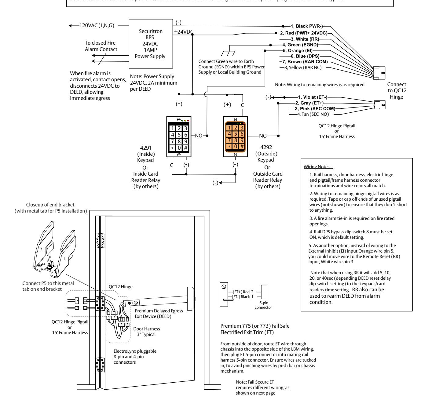
Delayed Egress System with Fail Safe Electrofied Exit Trim (ET) and ElectroLynx QC12 Hinge.
During a fire alarm condition, the fire alarm contact opens which removes power from DEED (rail) and Fail Safe ET, and allows immediate egress and ingress.
For External Inhibit (EI) control, a valid code entry at the Inside keypad or valid card presentation at Inside card reader shunts the rail and allows egress for a time period programmable at the keypad. A valid code entry at the Outside keypad or valid card presentation at Outside card reader removes power from the Fail Safe ET and allows ingress for a time period programmable at the keypad.
PED4000 D, PED5000 D Series Exit Device
Installation Instructions

17
System Wiring Examples ElectroLynx QC12 Hinge, Continued
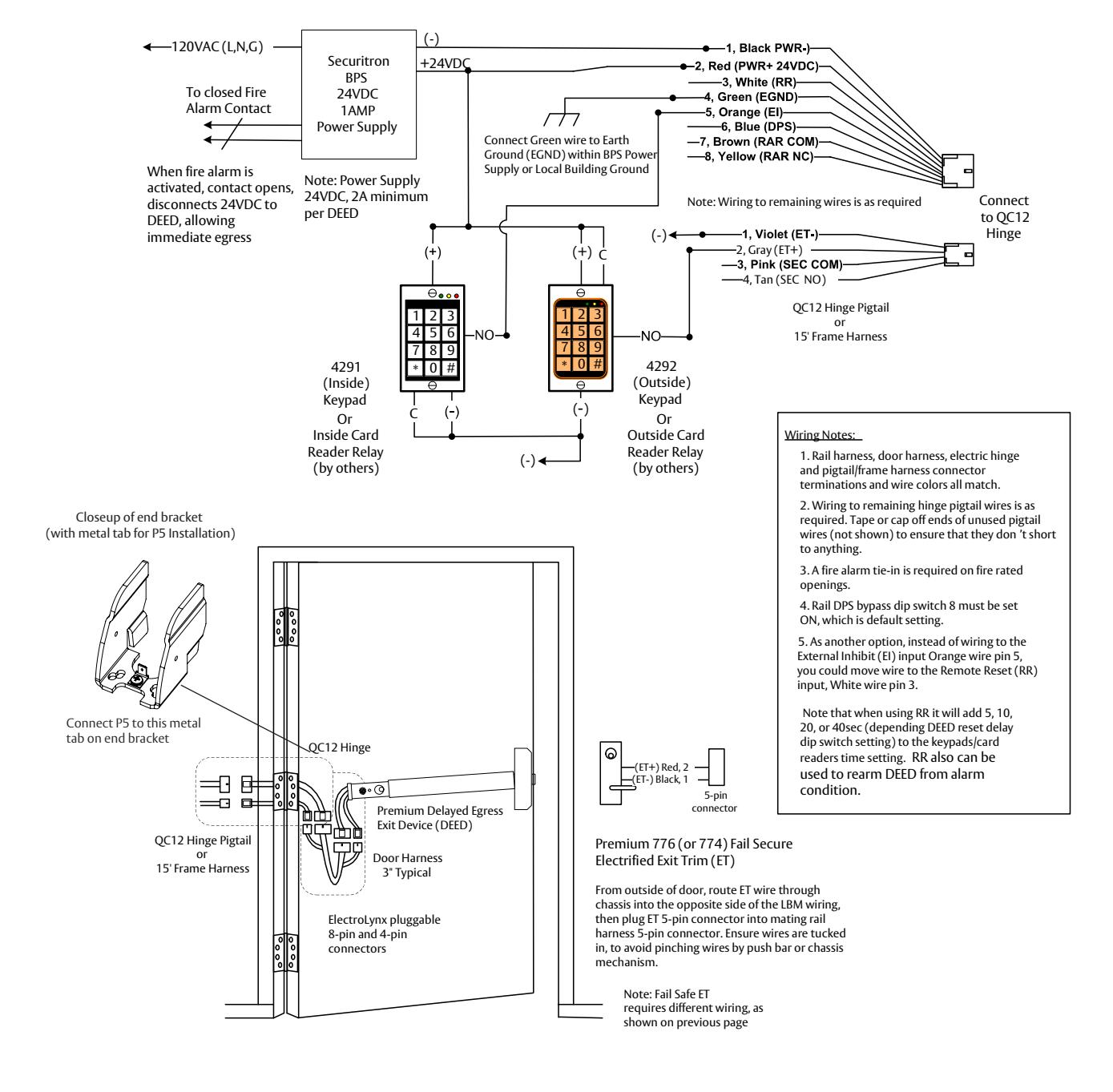
Delayed Egress System with Fail Secure Electrofied Exit Trim (ET) and ElectroLynx QC12 Hinge
During a fire alarm condition, the fire alarm contact opens which removes power from DEED (rail), and allows immediate egress. For External Inhibit (EI) control, a valid code entry at the Inside keypad or valid card presentation at Inside card reader shunts the rail and allows egress for a time period programmable at the keypad. A valid code entry at the Outside keypad or valid card presentation at Outside card reader applies power to unlock the Fail Secure ET and allows ingress by turning lever for a time period programmable at the keypad.
PED4000 D, PED5000 D Series Exit Device
Installation Instructions

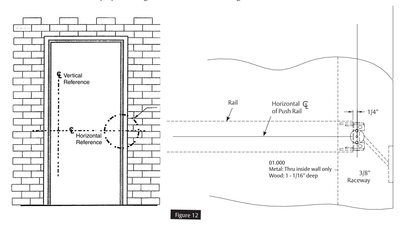
13 Field Wiring Door Prep
NOTE:
- Do not scale drawing.
- Dimensions are in inches (") and millimeters (mm)
- LHR H.M. opening shown. Details are typical for all opening materials (both hands).
- This preparation is an addition to preparation shown on device template.
- See device template to locate centerline.*
- Shields for wiring access recommended for insulated and composite doors.
- Locate and prepare wiring access holes when installing device.
PED4000 D, PED5000 D Series Exit Device
Installation Instructions

14 Operating Instructions
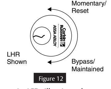
There are three (3) modes of operation (Figure 12):
- Delayed Egress
- Momentary Egress
- Bypass (Maintained) Egress
Delayed Egress Mode
- 1. Apply power to device. The initialization / self test sequence is as follows:
- Cover LED is GREEN for 2 seconds with horn sounding for 500ms.
- Cover LED is then RED for 2 seconds, followed by AMBER for 2 seconds with the 4 diagnositc LEDs illuminated.
- Cover LED is RED or GREEN (based on the setting of the Armed LED Color DIP Switch Position 6) and green diagnostic LED is illuminated. The device is now armed, which will not allow pushpad to retract latchbolt for immediate egress.
- 2. If the device is not functioning, refer to the Troubleshooting Guide.
Momentary Egress Mode (Figure 12)
- 1. With device armed, rotate key counter clockwise and return to center position (remove key).
- 2. Red LED (or LED color opposite the Armed LED Color Setting per DIP Switch Position 6) will flash quickly. Device will release for momentary egress for 10 seconds (factory set). 5, 10, 20, or 40 second reset delay may be selected using DIP Switch positions 4 and 5.
- 3. After the reset delay time has elapsed, or if the cylinder key is rotated a second time counter clockwise while the door/ DPS is closed during a reset delay, the device shall re-arm. When an external DPS is used and (DIP Switch position 7 is off) door is opened and closed during momentary egress, the selected reset delay shall be canceled and the device shall re-arm.
- 4. Device will now be back in delayed egress mode.
Bypass (Maintained) Egress Mode (Figure 12)
- 1. Rotate key clockwise, return key to center position and remove.
- 2. Cover LED is solid GREEN (default) or LED color opposite the Armed LED Color Setting per DIP Switch Position 6.
- 3. Device is disarmed, acting as a standard exit device which allows free egress.
Resetting device from Bypass Mode to Delayed Egress Mode (Figure 12)
- 1. Rotate key counter clockwise, return to center position and remove.
- 2. Cover LED is solid RED (default) or LED color setting per the Armed LED Color DIP Switch Position 6.
- 3. Device will be in delayed egress mode.
Delayed Egress Operation When Armed
Exit door is normally closed and latched. Delayed Egress device secures door in locked mode with solid red LED (default GREEN when DIP Switch Position 6 setting is OFF) indicating locked mode status.
Depressing pushpad for (1) one to three (3) seconds or less (depending on DIP Switch position 2 and 3 settings) will sound device nuisance beeps without initiating alarm.
Depressing pushpad longer than (1) one to three (3) seconds (depending on DIP Switch position 2 and 3 settings) will initiate an irreversible local audible alarm with a continuous tone, and a visual amber indicator.
After delay time (15 or 30 seconds), device releases, LED changes to green, (default, or red depending on the setting of DIP Switch position 6), and the local audible alarm remains as a continuous tone until reset by keyswitch.
Remote monitoring contact outputs can be used to alert security personnel. Person depressing pushpad is denied egress for 15 or 30 seconds (depending upon setup) and security personnel are alerted.
NOTE: 30 seconds may be accepted by local jurisdiction.
FM574 01/23
PED4000 D, PED5000 D Series Exit Device
Installation Instructions

14 Operating Instructions, continued
Re-arm After Closing for Indefinite Delay
With 40 second momentary egress setting (S2-4 ON & S2-5 ON), S2-7 ON, and an external DPS is wired to the PCBA (S2-8 OFF), after activation of momentary egress by cylinder key switch or external remote reset signal, if the Door/DPS is open beyond 40 seconds, it will remain in momentary egress mode indefinitely and shall not enter alarm mode. Then once the Door/DPS is closed, it will re-arm immediately. With (S2-4 ON & S2-5 ON) S2-8 OFF and S2-7 OFF for same scenario as above, the device will enter alarm mode after 40 seconds if the Door/DPS is still open. If Door/DPS is closed before 40 seconds, it will re-arm immediately.
15 Additional Options Non ElectroLynx Wiring
Electrically Controlled ET Trim "Safe/Secure"
The Delayed Egress Exit Device is available with Fail Safe (SAF) or Fail Secure (SEC) outside trim operation. In a fire condition, the Fail Safe trim will release for entry. When Access control is used, the Fail Secure trim allows entry by means of a remote card reader, keyswitch, push button, etc.
Note: If a Door Position Switch is not used, the trim will open the door without affecting the device in an armed condition (refer to wiring diagrams for wiring).
Note: If an external DPS is not used, Standard trim and Safe/Secure trim will allow entry without affecting the device in an armed mode. The device will only be affected when the push pad is depressed (refer to wiring diagrams for wiring).
16 BOCA 15 Second Delay BC-59_ and BOCA 30 Second Delay BC-59_
Upon depressing the pushpad for 1 second or longer, the device will sound an audible continuous tone and allow the door to be opened within 15 (or 30) seconds. The alarm will remain as a continuous tone until reset. Resetting of the alarm and re-arming of the device occurs automatically once the door has been returned to the closed position for 30 seconds. The 30-second re-arming timer will re-start if the pushpad is depressed or the door is re-opened before actual re-arming of the device occurs. A DPS (Door Position Switch) is required for the BOCA option.
NOTE: BOCA option is not suitable for installations in accordance with NFPA 101.
17 NFPA 101 Requirements: 30 Second Delay BC-59_ Suffix
Upon depressing the pushpad for 3 seconds or longer, the device will sound an audible continuous tone and allow the door to be opened after 30 seconds. The alarm will remain as a continous tone until reset. Resetting of the alarm and re-arming of the device is accomplished by manual means only.
PED4000 D, PED5000 D Series Exit Device
Installation Instructions

18 Troubleshooting
| Problem | Solution |
|---|---|
|
Power is applied, but unit will not arm
(No red LED) |
•
Check all connections on circuit board and wire harness. • Check for power 24VDC at power inputs (-black) and (+red) and check polarity. • Check wire transfer for any bad connections or broken wires. • Check power output at power supply. • Must be 24VDC regulated. |
|
Device alarms continuously when power
is applied. |
•
Check pushpad position sensor wire harness on circuit board and all other connections. • Check that the position of the pushpad matches the status of the RED Diagnostic LED (See table on Page 27 for details.). |
|
Units with Door Position Switch (made
by other manufacturers) |
•
Make sure DPS is wired (electrically closed - with door closed) into wire harness. Make sure DPS is working properly by using a meter to check continuity when door is opened and closed. |
|
Device allows mechanical latchbolt
retraction with power applied and LED shows armed. |
•
Check for correct power, 24VDC regulated. • Check for correct amperage on power supply (must be rated equal or greater than device, 1A minimum). |
|
Exit device latchbolt/rods will not latch
properly. |
•
Refer to standard exit device installation instructions troubleshooting guide. |
|
LED on rail cover is flashing fast Amber
color (once every 300ms) and rail buzzer is activated. Door was forced open (DPS was opened) |
•
Close/secure door, check DPS for proper operation, then reset rail using cylinder key, or remote rest signal. |
|
LED on rail cover is flashing slow Amber
color (once every 1 sec) and rail buzzer is activated. Latch bolt was retracted for 10sec. |
•
Close/secure door, ensure latch is extended, then reset rail using cylinder key, or remote rest signal. |
NOTE: If device is not working properly after troubleshooting, contact your local hardware distributor or local Corbin Russwin representative, or contact Corbin Russwin.
PED4000 D, PED5000 D Series Exit Device
Installation Instructions

18 Troubleshooting, continued
Symptom / Failure
A. Rail won't arm (Green Insert LED won't turn ON / Horn sounds immediately or after a delay)
• When trying to arm, the rail goes into alarm immediately after momentary egress times out or after a short delay after the momentary egress times out.
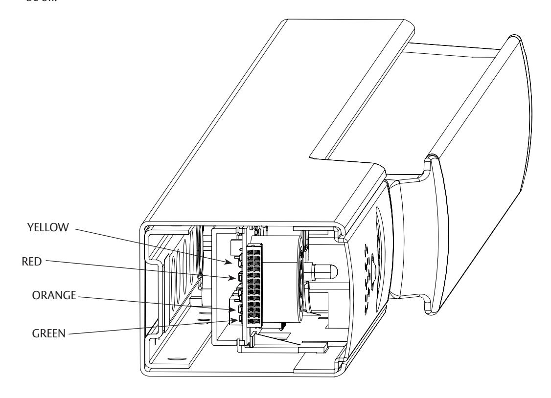
Are the Yellow, Red, Orange, and Green circuit board Diagnostic LEDs OFF?
YES – Replace defective circuit board.
* NO – All of these LEDs should be OFF. Troubleshoot according to which LED is ON. If any LED stays ON after troubleshooting according to *, then replace defective circuit board.
B. Rail won't arm(Green Insert LED won't turn ON / Horn stays OFF)
- The rail is receiving an external inhibit signal.
- The rail is in fire alarm condition.
C. Rail Arms, but will not go into alarm when depressing push bar
• Does the Red Diagnostic LED turn ON when depressing push bar?
YES – Replace defective circuit board.
NO – The push rail position sensor is malfunctioning. The rail assembly will need to be replaced.
D. Cover LED fast flashes alternately RED then GREEN every 0.5 seconds (*Hall Error Mode); Horn/Diagnostic LEDs are off.
- The rail may or may not arm prior to this error code.
- Check harnesses are connected to the controller PCBs.
- Push rail hall switch circuit defective or out of activation range. Consult 1-800-810-WIRE (9473).
- If the push bar was in the dogged (retracted) position using a 24 VDC power cycle (via fire alarm/reset or temporary power outage), this hall error mode will occur. To clear error, un-dog push bar with manual hex key, ensure bar extends fully then turn cylinder key clockwise to maintained egress position, then counter-clockwiase to Armed (center) position (or cycle 24 VDC power) to rearm device.
*If horn sounds or flashing sequence differs from the above; or if error mode does not clear, consult 1-800-810-WIRE (9473).

Important: Rail is not armed when in this condition.
Attention: Electrified Trim applications require a separate raceway and power transfer device. Installation of conductors or harnesses (by others) through the exit device rail is prohibited as it could lead to product performance issues up to and including product failure.
PED4000 D, PED5000 D Series Exit Device
Installation Instructions

18 Troubleshooting, continued
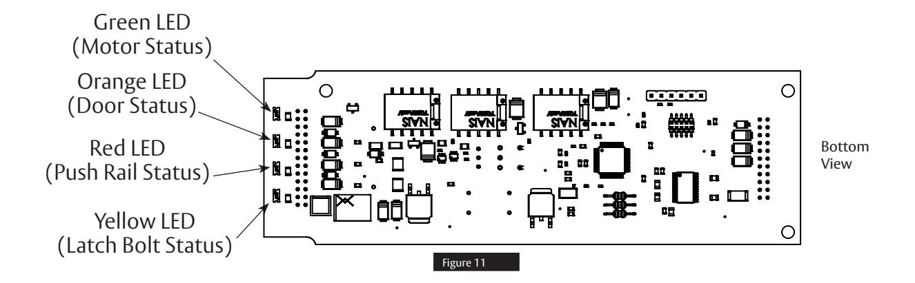
Refer to the following table and notes for an explanation of each LED's function.
| Diagnostic LEDs | Function |
|---|---|
| Yellow (Latch Bolt Status) | ON - Latch bolt is retracted |
| OFF- Latch bolt is extended | |
| Red (Push Rail Switch) | ON- Rail Push Bar is depressed. |
| OFF- Rail Push Bar is released. | |
| Orange (Door Status Switch) | ON- Door Status Switch is open. Door is open/violated. |
| OFF- Door Status Switch is closed or DPS Bypass DIP switch position 6 is ON. | |
| Green (Solenoid) | ON- Motor is in blocked/locked/armed postion. |
| OFF- Motor is in unblocked/disarmed position |
NOTES:
- 1. When the rail is armed (in Delayed Egress Mode) and the door is closed and latched, the Green Diagnostic LED should be ON only. All other LEDs should be OFF.
- 2. With the rail armed, depressing the rail push bar slightly will turn the Red Diagnostic LED ON. The rail should go into alarm immediately (no nuisance delay) or after being pressed for 1, 2, or 3-second nuisance delay setting. The rail will be in the irreversible alarm mode and Cover LED is Amber with local audible beeping tone. After a standard delay of 15 seconds (or 30-second optional delay), the motor unblocks and passage is allowed. Cover LED is green (or red depending on DIP Switch position 6 setting) with alarm at a steady tone which continues until reset by key switch.
- 3. When a Door Status switch is used and the door is opened, the Orange Diagnostic LED will turn ON, which indicates that the door is not closed. When not using a door status switch, DIP switch position 7 must be set to ON, Orange Diagnostic LED shall be off.
PED4000 D, PED5000 D Series Exit Device
Installation Instructions


Corbin Russwin 225 Episcopal Road Berlin, CT 06037 Phone: 800-543-3658 Fax: 800-447-6714
corbinrusswin.com
Copyright © 2023 ASSA ABLOY Access and Egress Hardware Group, Inc. All rights reserved. Reproduction in whole or in part without the express written permission of ASSA ABLOY Access and Egress Hardware Group, Inc. is prohibited. Patent pending and/or patent - www.assaabloydss.com/patents. HID, iCLASS, and Edge are trademarks or registered trademarks of HID Global Corporation.

Corbin Russwin 225 Episcopal Road Berlin, CT 06037 Phone: 800-543-3658 Fax: 800-447-6714
corbinrusswin.com
Copyright © 2023 ASSA ABLOY Access and Egress Hardware Group, Inc. All rights reserved. Reproduction in whole or in part without the express written permission of ASSA ABLOY Access and Egress Hardware Group, Inc. is prohibited. Patent pending and/or patent - www.assaabloydss.com/patents. HID, iCLASS, and Edge are trademarks or registered trademarks of HID Global Corporation.