Corbin Russwin IN120 Cylindrical Installation Instructions_FM354
Open the original PDF document
View PDFCylindrical Lockset IN120 WiFi Installation Instructions
Attention Installer
Please read these instructions carefully to prevent missing important steps.
Misalignment can cause premature wear and a lessening of security.
Please Note: Improper installations may result in damage to the lock and void the factory warranty. Important: The accuracy of the door preparation is critical for proper functioning and security of this lock.
WARNING
This product can expose you to lead which is known to the state of California to cause cancer and birth defects or other reproductive harm. For more information go to www.P65warnings.ca.gov.
08/2018
For Technical Assistance call Corbin Russwin at 1-800-810-WIRE (9473)

Table of Contents
| 1) Warning | 2 |
|---|---|
| 2) General Description | 3 |
| 3) Specifications / Features | 3 |
| 4) Product Illustration | 4 |
| 5) Installation Instructions | 6 |
| 6) Operational Check | 17 |
1) Warning
Warning: Changes or modifications to this unit not expressly approved by the party responsible for compliance could void the user's authority to operate the equipment.
This device complies with Part 15 of the FCC Rules. Operation is subject to the following two conditions: (1) this device may not cause harmful interference, and (2) this device must accept any interference received, including interference that may cause undesired operation.
Note: This equipment has been tested and found to comply with the limits for a Class B digital device, pursuant to Part 15 of the FCC Rules. These limits are designed to provide reasonable protection against harmful interference in a residential installation.
This equipment generates, uses and can radiate radio frequency energy and if not installed and used in accordance with the instructions, may cause harmful interference to radio communications. However, there is no guarantee that the interference will not occur in a particular installation. If this equipment does cause harmful interference to radio or television reception, which can be determined by turning the equipment off and on, the user is encouraged to try to correct the interference by one or more of the following measures:
- Reorient or relocate the receiving antenna
- Increase the separation between the equipment and receiver
- Connect the equipment into an outlet on a circuit different from that to which the receiver is connected
- Consult the dealer or an experienced technician for help
The term "IC:" before the radio certification number only signifies that Industry Canada technical specifications were met. This Class B digital apparatus meets all requirements of the Canadian Interference Causing Equipment Regulations. Operation is subject to the following two conditions: (1) this device may not cause harmful interference, and (2) this device must accept any interference received, including interference that may cause undesired operation.
Cet appareillage numérique de la classe B répond à toutes les exigences de l'interférence canadienne causant des règlements d'équipement. L'opération est sujette aux deux conditions suivantes: (1) ce dispositif peut ne pas causer l'interférence nocive, et (2) ce dispositif doit accepter n'importe quelle interférence reçue, y compris l'interférence qui peut causer l'opération peu désirée.

To comply with "Fire Listed" doors, the batteries must be replaced with alkaline batteries only.
To avoid possible damage from electrostatic discharge (ESD), some basic precautions should be used when handling electronic components:

- Minimize build-up of static by touching and/or maintaining contact with unpainted metal surfaces such as door hinges, latches, and mounting plates especially when mounting electronic components such as readers and controllers onto the door.
- · Leave components (reader and controller) protected in their respective anti-static bags until ready for installation
- Do not touch pins, leads or solder connections on the circuit boards
*Any retrofit or other field modification to a fire rated opening can potentially impact the fire rating of the opening, and Corbin Russwin, Inc. makes no representations or warranties concerning what such impact may be in any specific situation. When retrofitting any portion of an existing fire rated opening, or specifying and installing a new fire-rated opening, please consult with a code specialist or local code official (Authority Having Jurisdiction) to ensure compliance with all applicable codes and ratings.
Copyright © 2016 Corbin Russwin, Inc. All rights reserved. Reproduction in whole or in part without the express written permission of Corbin Russwin, Inc. is prohibited.
ASSA ABLOY, the global leader in door opening solutions

2) General Description
The Corbin Russwin IN120 WiFi lock offers the ease and flexibility of WiFi in a streamlined design, setting a new standard for aesthetics and performance. The IN120 uses IEEE 802.11 WiFi communication and a flexible feature set for easier, more cost-effective installations, allowing facilities to leverage their IT infrastructure to expand access control coverage to more doors. Featuring HID® multiCLASS SE® technology, it supports heightened identity security and multiple credentials, including NFC-enabled mobile phones.
This product is operated by six (6) "AA" alkaline batteries, or can be hard-powered using an optional 9-24VDC power supply connected by a harness through the door.
Corbin Russwin cylindrical locks are designed with quality components to provide high security, performance and durability.
3) Specifications / Features
Hardware Specifications
- Latch Stainless steel, ½" (13mm) throw Optional: ¾" (19mm) throw deadlocking fire latch for pairs of doors
- Deadlocking latch prevents manipulation when door closed
- Door Thickness 1-3/4" (44mm) to 2" (50mm) Standard Optional 2" (50mm) to 2-1/4" (57mm) optional
- Outside lever controlled by any combination of contactless reader or mechanical cylinder
- Inside lever retracts latch
- May be used for indoor and outdoor applications
- ANSI/BHMA A156.25 Listed Grade 1 Compliant
NOTE: A weather-protective gasket is required for outdoor applications.

3) Specifications / Features (Continued)
Electrical Specifications:
-
HID® multiCLASS SE® technology offers support for the following credentials:
-
2.4 GHz credential compatibility:
- Secure Identity Object™ (SIO) on Mobile IDs (Bluetooth Smart)
-
13.56 MHz credential compatibility:
- iCLASS®
- iCLASS SE® (SIO-enabled)
- iCLASS Seos®
- SIO on MIFARE® Classic
- SIO on MIFARE® DESfire® EV1
- MIFARE® Classic
- DESfire® EV1
- NFC-enabled mobile phones
-
125 kHz credential compatibilty:
- HID Prox®
-
2.4 GHz credential compatibility:
- WiFi (IEEE 802.11 b/g/n)
- Multiple time zone and holiday access scheduling
- First-in unlock or automatic unlock configuration, based on specified time schedule
- Support for most advanced wireless encryption and authentication standards such as WEP, WPA, WPA2 and 802.1x*
- 2,400 users per lock; 10,000 event audit trail
- Privacy button
- 8200 lock body offers monitoring of deadbolt REX and provides integrated monitoring of door position
Power requirements:
- Alkaline AA Batteries: 9V, 300mA
- Optional Hard Power (UL294 Listed Power Supply Required): 9-24VDC, 300mA
- UL Listed UL 294 Indoor Use
- CUL Listed S319: Class 1
- UL 294 Access Control Ratings :
| Destructive Attack | Level 1 |
|---|---|
| Line Security | Level 1 |
| Endurance | Level 4 |
| Standby Power | Level 1 |
* For specific security information, please contact your local ASSA ABLOY Door Security Solutions sales consultant or call 800-810-WIRE.

4) Product Illustration
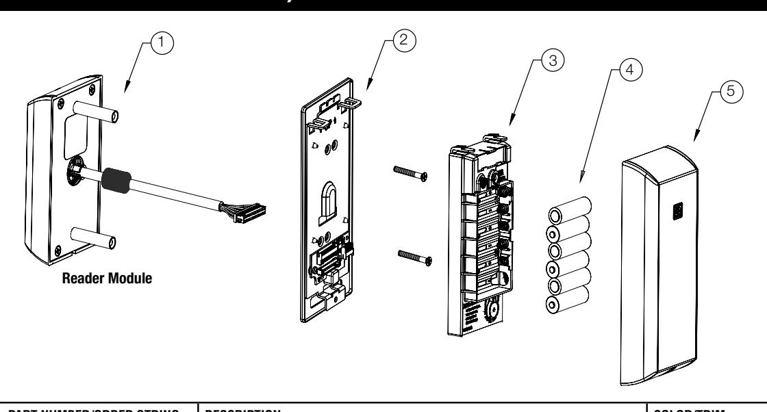
| ITEM | PART NUMBER/ORDER STRING | DESCRIPTION | COLOR/TRIM | QTY |
|---|---|---|---|---|
| 1* | IN-120-EM01-[B]IP-B |
HID iCLASS®, HID iCLASS SE® (SIO-enabled), HID iCLASS® Seos™, HID MIFARE®
SE, HID DESfire® EV1 SE, HID Prox®, NFC-enabled mobile phones |
Black | 1 |
| IN-120-EM01-[B]IP-W |
HID iCLASS®, HID iCLASS SE® (SIO-enabled), HID iCLASS® Seos™, HID MIFARE®
SE, HID DESfire® EV1 SE, HID Prox®, NFC-enabled mobile phones |
White | 1 | |
| IN-120-EM01-[B]IP-MB-[finish]** |
HID iCLASS®, HID iCLASS SE® (SIO-enabled), HID iCLASS® Seos™, HID MIFARE®
SE, HID DESfire® EV1 SE, HID Prox®, NFC-enabled mobile phones |
Black with metal trim | 1 | |
| IN-120-EM01-[B]IP-MW-[finish]** |
HID iCLASS®, HID iCLASS SE® (SIO-enabled), HID iCLASS® Seos™, HID MIFARE®
SE, HID DESfire® EV1 SE, HID Prox®, NFC-enabled mobile phones |
White with metal trim | 1 | |
| IN-120-EM01-[B]IPS-B | All credentials supported by the IP option plus MIFARE Classic and DESfire EV1 | Black | 1 | |
| IN-120-EM01-[B]IPS-W | All credentials supported by the IP option plus MIFARE Classic and DESfire EV1 | White | 1 | |
| IN-120-EM01-[B]IPS-MB-[finish]** | All credentials supported by the IP option plus MIFARE Classic and DESfire EV1 | Black with metal trim | 1 | |
| IN-120-EM01-[B]IPS-MW-[finish]** | All credentials supported by the IP option plus MIFARE Classic and DESfire EV1 | White with metal trim | 1 | |
| IN-120-EM01-[B]CP-B | FeliCa, HID Prox®, NFC-enabled mobile phones | Black | 1 | |
| IN-120-EM01-[B]CP-W | FeliCa, HID Prox®, NFC-enabled mobile phones | White | 1 | |
| IN-120-EM01-[B]CP-MB-[finish]** | FeliCa, HID Prox®, NFC-enabled mobile phones | Black with metal trim | 1 | |
| IN-120-EM01-[B]CP-MW-[finish]** | FeliCa, HID Prox®, NFC-enabled mobile phones | White with metal trim | 1 | |
| 2 | 782F718 | Inside Mounting Kit (mounting plate & hardware) | 1 | |
| 3 | 783F519 | WiFi Controller | 1 | |
| 4 | N/A | AA battery | 6 | |
| 5 | 782F729 | Inside Escutcheon | Black | 1 |
| 782F739 | Inside Escutcheon | White | ||
| 783F725 FIN** | Inside Escutcheon | Black with metal trim | ||
| 783F735 FIN** | Inside Escutcheon | White with metal trim | ||
| 6 | FM355 | Field prep template (not shown) | 1 | |
| 7 | T31202 | Door manufacturers template (not shown) | 1 | |
| FM354 | Instructions (this manual) | 1 |
* Specifying B indicates BLE (Bluetooth) option when ordering
** Specify finish

4) Product Illustration (Continued)
Tools Required:
- Phillips Screw Driver #2, #3
- Flat Blade Screw Driver (Standard size)
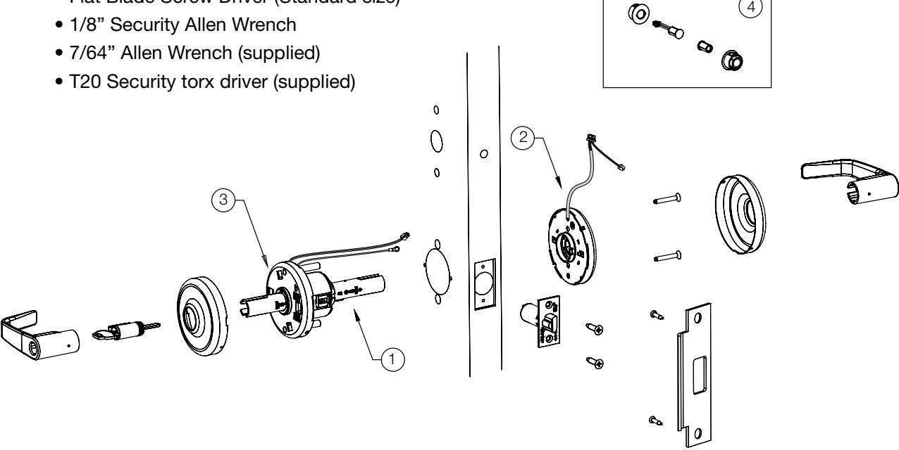
| 1 | 783F918 | CL33134 Cylindrical lock with fixed core cylinder | 1 |
|---|---|---|---|
| 783F928 | CL33134 Cylindrical lock with removable core cylinder | ||
| 2 | 783F889 | Inside Spring Cassette - IN120 REX | 1 |
| 3 | 682F268 | Outside Spring Cassette (1-3/4" - 2" Door) | 1 |
| 682F278 | Outside Spring Cassette (2" - 2-1/4" Door) | ||
| 4 | 783F619 | DPS (Door Position Switch) Kit | 1 |
For parts not listed, refer to CL3300 Parts and Service Manual

5) Installation Instructions
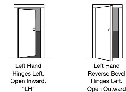
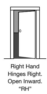
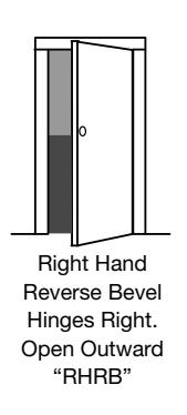
1. Verify Hand and Bevel of door
Illustrations shown are as viewed from the outside or secure side of opening.
"LHRB"
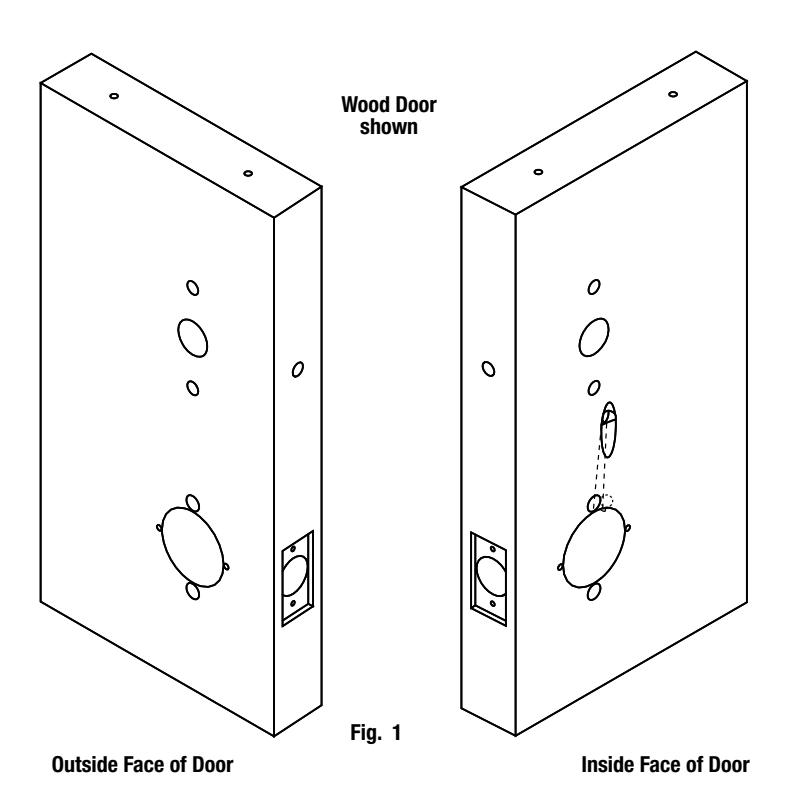
2. Door Preparation
Prep door according to supplied door marker (FM356). For door manufacturer templates visit www.corbinrusswin.com and reference template # T31203.

5) Installation Instructions (Continued)
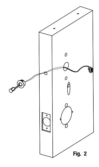
3. Install Door Position Switch (DPS)
- a. Insert DPS into the raceway on the latch edge of the door.
- b. Push wires through raceway toward lock prep.
- c. Push DPS firmly into place by hand. Note: DO NOT TAP SWITCH WITH ANY TOOL.
- d. Install magnet into door frame. Push firmly into place by hand. See instruction A7983 .
CAUTION: if DPS is not installed or is installed improperly, door status monitoring features will not function.
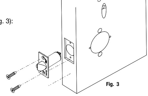
4. Install Latch Bolt
Install latch bolt with beveled bolt facing the strike using two #8 x 3/4" combination screws (Fig. 3):
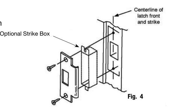
5. Install Strike Plate
Install Strike Plate using two #12 x 1" combination screws (Fig. 4):

5) Installation Instructions (Continued)
6. Install Lock Body
a. Feed lock body and wire through 2-1/8" diameter hole from outside of door (Fig. 5a). Be sure latch engages lock body as shown (Fig. 5b).
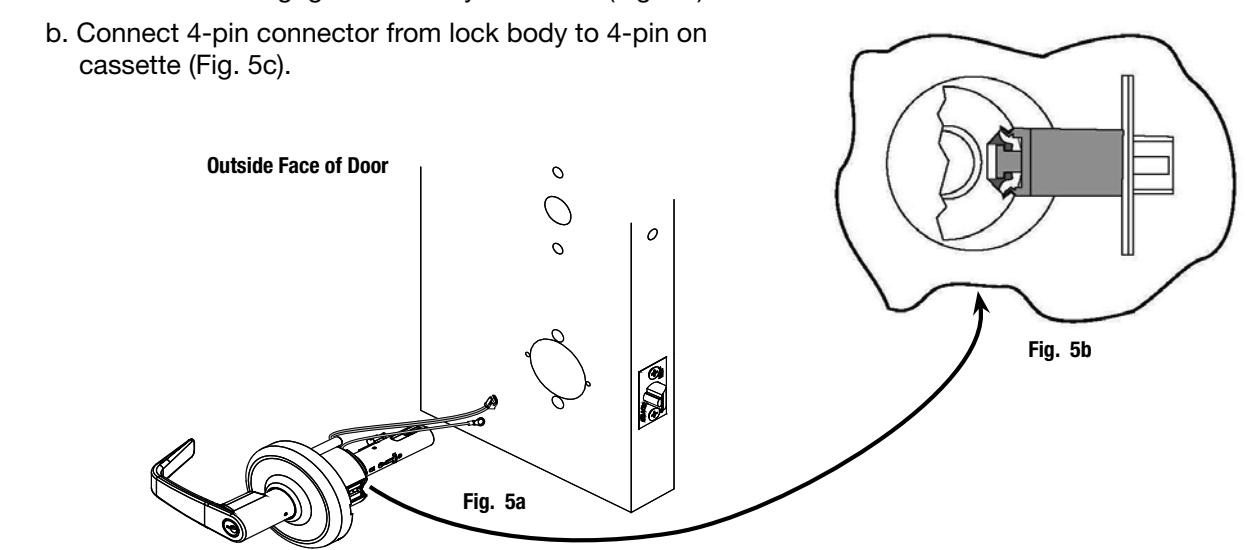
c. Temporarily install top throughbolt to hold chassis in door (Fig. 5c). Important: Door must remain open during installation. Use door stop.
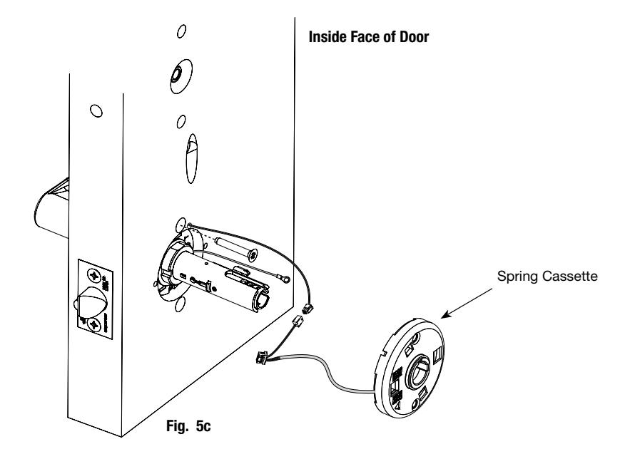

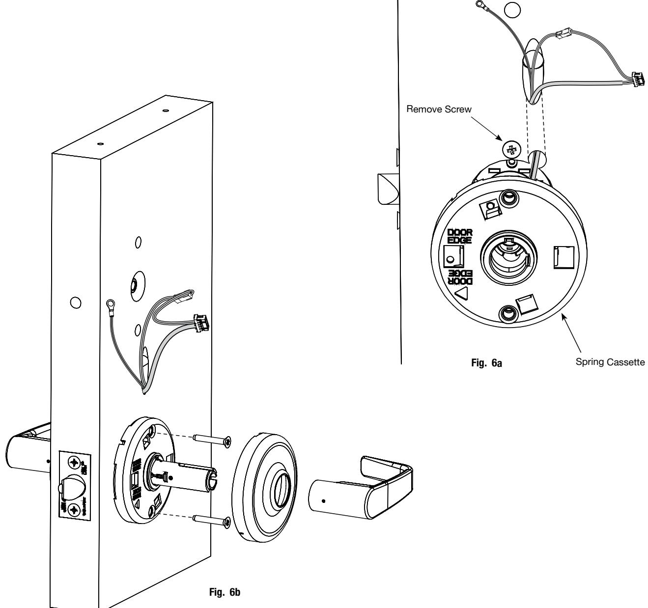
7. Install Inside Spring Cassette Lock
- a. Feed harness wires and ground wire up through raceway (Fig. 6a).
- b. Remove screw from previous step.
- c. Slide on cassette and secure with (2) screws.

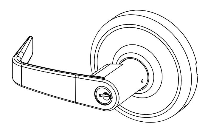
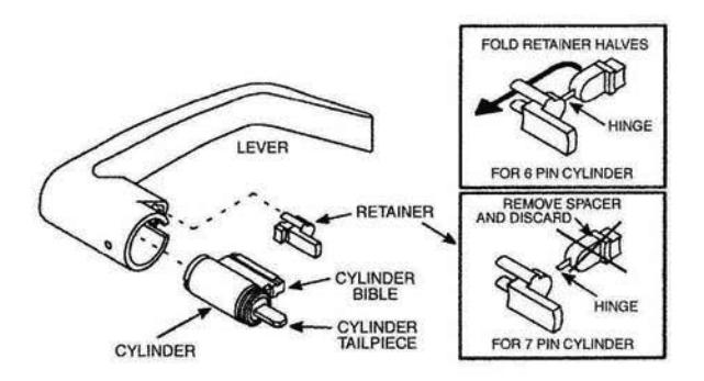
8. Installation and Removal of Lever and Standard Cylinder
| LEVER STYLE | REMOVAL | INSTALL | |
|---|---|---|---|
| PLAIN LEVER | PUSH RELEASE TOOL | SLIDE LEVER OVER | |
| RELEASE HOLE ASSEMBLY |
Push release tool
Into release hole, Remove lever |
Slide lever over
Lever catch Pull on lever. Make sure lever will not pull off |
|
| CYLINDER LEVER RELEASE HOLE ASSEMBLY RELEASE TOOL | ROTATE KEY Rotate key 45° clockwise (from shed position), Push in release tool into Release hole, remove lever | INSERT KEY AND ROTATE Insert key and rotate 45° (from Shed position), slide lever on Make sure lever will not pull off | |
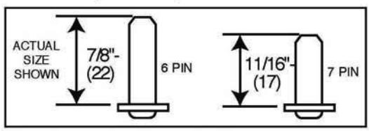

9. Install Outside (Reader) Escutcheon
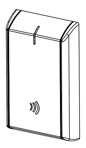
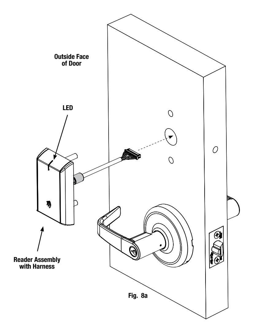
- a. Orient the reader so the LED lens is at the top.
- b. Feed the reader harness through the door (from outside to inside).
- c. Install the reader to the outside of door by aligning the mounting posts with the door preparation holes. Hold the reader flush against door while ensuring proper alignment.

9. Install Outside (Reader) Escutcheon - (Continued)
d. Next feed the cables/connectors through the inside mounting assembly (and gasket if required*).
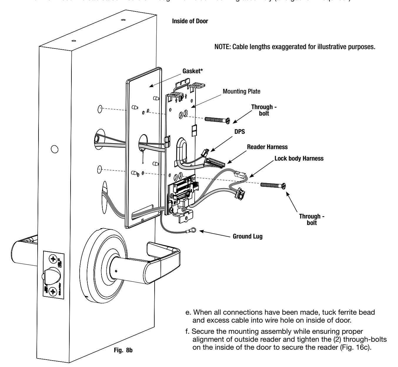
* Gasket is required for outdoor installations.
If installing with gasket; separate gasket from mounting plate to feed cables/connectors through holes as indicated (Fig. 8b).
Once cables/connectors are fed through, reattach gasket to mounting plate.

(10-pin)
5) Installation Instructions (Continued)
10. Installation of Connectors
Installation of Connectors
CAUTION - Do not touch or allow debris to enter connector contacts.
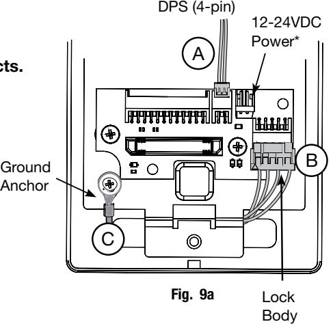
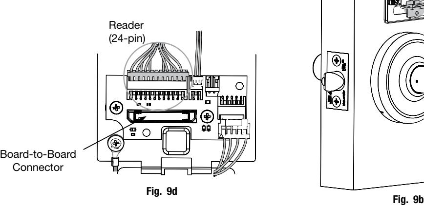
Secure the following connectors to their respective terminals (Fig. 9a ):
- A. Secure the 4-pin DPS connector.
- B. Secure the 10-pin lock body assembly connector.
- C. Secure ground lug to #6-32 machine screw.
*NOTE: Optional 2-pin external 12-24VDC power connector.
IMPORTANT: Do not run wires through hole in plate (Fig. 9c) - this will damage wires and the controller connector.
Route wires around flange, do not route wires through the flange hole (Fig. 9c,d).
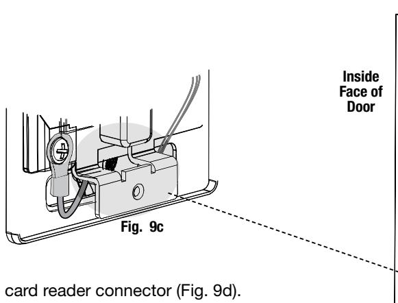
D. Secure the 24-pin card reader connector (Fig. 9d).

11. Install Inside Module Component Assembly
- 1. Insert top tabs of controller into slots on mounting plate (Fig. 10).
- 2. Ensure proper alignment of board-to-board connectors while pivoting bottom of controller toward door until tab on bottom snaps securely into place on mounting plate.
CAUTION : To avoid possible damage to board-to-board connectors, care should be taken when securing controller to mounting plate. If there is resistance when securing, detach controller to determine cause before re-attaching controller.
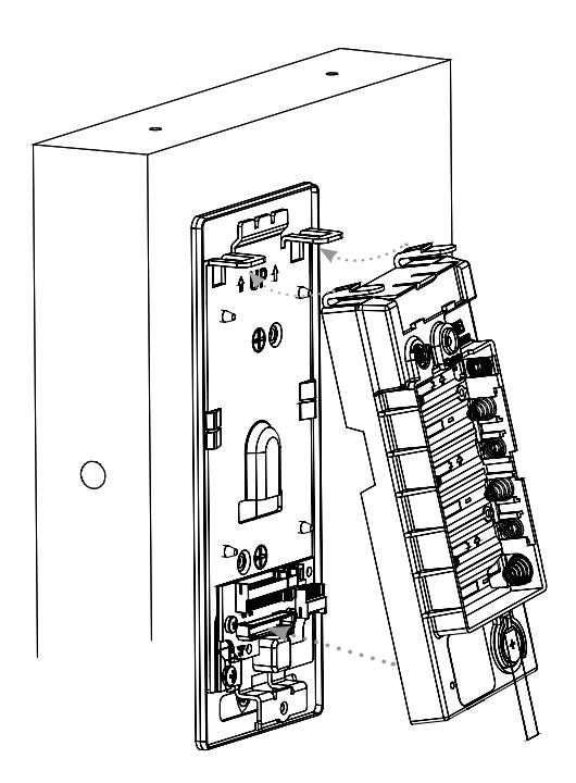
Fig. 10

12. Battery Installation
Before installing batteries for the first time:
Remove pull tab from its position beneath the coin cell by pulling on tab in direction of arrows printed on tab (Fig. 11).
- a. Place (6) "AA" alkaline batteries in the compartment, being careful to align polarity properly.
- b. After batteries are installed, there is a slight delay; then an audible "beep" will sound and the lock motor will cycle.
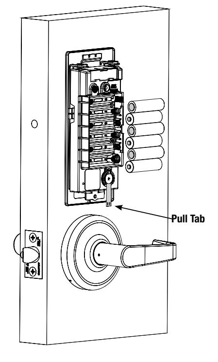
Fig. 11
13. Inside Cover Installation
- a. Assemble cover by hooking top edge on inside mounting plate.
- b. Carefully press bottom of cover toward door without pinching any wires.
- c. Secure cover utilizing security allen wrench.
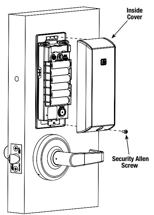
Fig. 12

6) Operational Check
When lock is fully installed, perform the following steps:
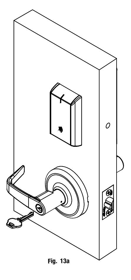
- a. Insert key into cylinder and rotate (Fig. 13a).
- b. There should be no friction against lock case, wire harness or any other obstructions.
- c. Check that the key retracts the latch.
- d. The key should rotate freely.
- e. Try the inside lever; ensure it retracts latch.
- f. Use a valid credential* set up with the Lock Configuration Tool to unlock outside lever and retract latch.
Refer to Network and Lock Configuration Tool user manual ( WFMN1 ) for information on how to configure and program locks.
* Twenty (20) seconds after lock initialization (single beep with lock motor actuation).
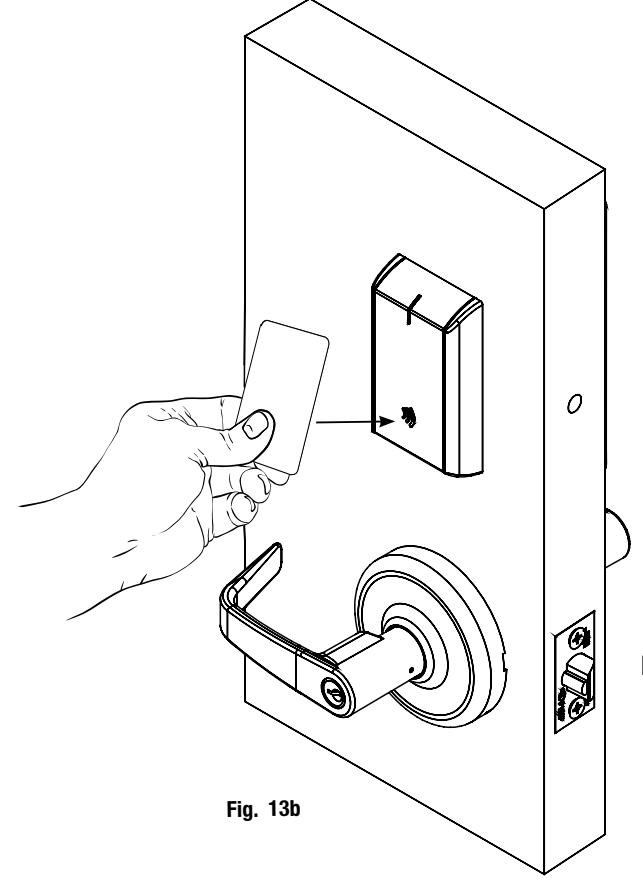
Note: The credential should approach the inscription on the reader as indicated (Fig. 13b) to ensure that the credential is read properly.
Do not wave credential.
| Notes | |
|---|---|

Copyright © 2016 Corbin Russwin, Inc., an ASSA ABLOY Group company. All rights reserved. Reproduction in whole or in part without the express written permission of Corbin Russwin, Inc. is prohibited.