Corbin Russwin Heavy Duty Cylindrical Lockset Installation Instructions
Open the original PDF document
View PDF

ASSA ABLOY
HEAVY DUTY CYLINDRICAL LOCKSETS SERRURES CYLINDRIQUES EXTRA-ROBUSTES
How To Install - Pose Des
ADJUSTABLE FOR DOORS 35 mm (1-3/8") TO 51 mm (2") AJUSTABLE POUR PORTES 35 mm (1-3/8") A 51 mm (2")
MARK DOOR FAIRE LES MARQUES
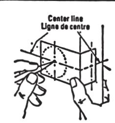
Scribe center line of latch bolt on door. Mark center of latch at center of door edge. Apply template to center line and mark center of hole for lock case. Tracer la ligne de centre du pêne sur la porte. Marquer le centre du loquet au centre de l'épaisseur de la porte. Placer le gabarit sur la ligne de centre et pointer le centre du trou pour la serrure.
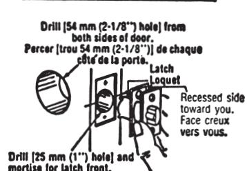
Drill [25 mm (1") hole] and mortise for latch front. mortise for latch front. Percer [trou 25 mm (1")] et mortalser pour la face du loquet.
Drill 54 mm (2-1/8") hole thru stile as marked. Drill from both sides. Drill hole for latch as marked (25 mm (1") hole). Mortise for latch front. Position latch and front. ror laten front. Position latch and front. Suivant les marques, percer un trou de 54 mm (2·1/8") dans le montant, en perçant de chaque côté. Percer le trou de 25 mm (1") pour le loquet. Mortaiser pour la face. Mettre le loquet et la face en place.
3 DETACH INSIDE TRIM ENLEVER LA POIGNEE INTERIEURE
ADJUST LOCK AJUSTER LA SERRURE
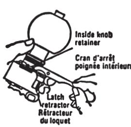
Exert pressure against inside knob retainer on side lacing latch retractor, using small end of spanner wrench. At the same time a slight pressure of the thumb will release the knob. A l'aide de la cle fournie, enfoncer le cran d'arrêt qui est face au retracteur du loquet. Exercer en même temps une légère pression du pouce sur la poignée pour la dégager.
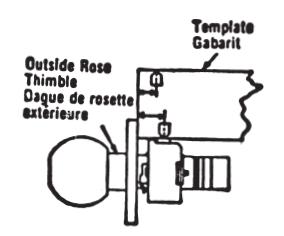
Adjust lock to fit door thickness by rotating outside rose thimble until proper distance is reached in accordance with instructions on back of template furnished. Suivant les instructions données au verso du gabarit fourni, ajuster selon l'épaisseur de la poite en tournant la bague de la rosette extérieure.
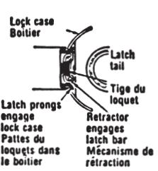
Insert tatch in door. Insert tock into tock case hole from outside. Be sure that the lock case engages latch prongs and latch tail engages retractor (see illustrations at left and below). Turn knob—See that latch moves freely. DO NOT FORCE. If necessary alter lock case hole for free engagement. Insert latch in door, Insert engagement. Placer le loquet dans la porte. Placer la serrure dans le trou du boîtier du
dans le trou du boîtier du câle extérieur. Les pattes du loquet doivent s'engager dans le boîtier de la serrure et la tige du loquet s'engage dans le mécanisme de rétraction (Voir illustr. a gauche et ci-dessous). Tourner la poignée—Le loquet doit se mouvoir sans entrave. NE PAS FORCER. Ajuster au besoin le trou du boîtier.
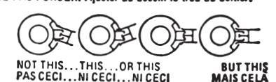
SEAT LOCK INTO POSITION
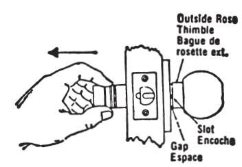
Applying pull pressure from Inside, rotate outside rose thimble until slot in thimble is facing front and snaps into rose, eliminating
gap. En tirant du côté inférieur, tourner la bague de la rosette extérieure; l'encoche dans la bague doit être vers l'avant et s'enloncer dans la rosette éliminant l'espace.
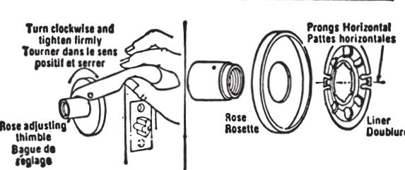
Attach Inside rose liner and rose by screwing thimble on threaded sleeve. Tighten with wrench pro-
Poser la rosette intérieure et sa dou-blure en vissant la bague sur le man-chon. Serrer a l'aide de la clé fournie.
Tournie. Caution: Outside rose must be tight against door and gap shown in step 6 eliminated. Attention: La rosette éxterieure doit être serrés sur la porte et l'espace montré au no 6 éliminé.
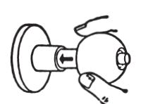
REPLACE INSIDE KNOB POSER LA POIGNÉE INTERIEURE
N WARNING This product can expose you to lead which is known to the state of
California to cause cancer and birth defects or other reproductive harm. For more information go to www.P65warnings.ca.gov
SLOCATE STRIKE POSITION DE LA GÁCHE
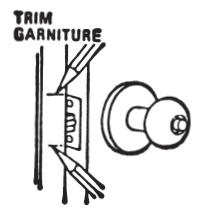
To locate position of strike on jamb, close door until latch bolt touches jamb. Mark EDGE of jamb as shown, Fermer la porte pour que le pêne touche le cadre. Marquer le BORD du cadre tel qu'illement.
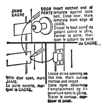
10 INSTALL STRIKE
TO REMOVE OUTSIDE KNOB FOR CHANGE OF HAND OR RE-KEYING POUR INVERSER LA MAIN OU POUR ENLEVER LE BARILLET
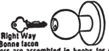
Right Way Bonne Iacon Cyfinders are assembled in knobs for right or lett hand doors as ordered. If it becomes necessary to change the hand of a lock so that cylinder will be right side up, see instructions
below. Les barillets sont posés dans les poignées pour des portes ouvrant à droite ou à gauche selon la commande. Voir les instructions ci-dessous s'il est nécessaire de changer la main de la serrure pour que le barillet soit du bon côté. A. Back off inside thimble and push against inside knob until outside knob retainer is
back off inside timinue and post agency exposed. Retirer la bague inférieure et poisser sur la poignée intérieure pour exposer le cran d'arrêt de la poignée extérieure. Depress retainer and pull outside knob off. Enfoncer le cran d'arrêt et enlever la poignée extérieure en tirant. To re-install, Snap knob into position, follow step 6 and secure lock by re-tightening Inside thimble with wrench.
Inside thimble with wrench, Pour reposer, enigncer la poignée en place et suivre les instructions du no 6; resserrer la bague inlérieure à l'aide de la clé fourme.
Corbin Russwin, Inc. 225 Episcopal Road Berlin, CT 06037 USA Phone: 800-543-3658
ASSA ABLOY Door Security Solutions Canada 160 Four Valley Drive Vaughan, Ontario, Canada L4K 4T9
Phone: 800-461-3007
Technical Product Support:
INSTRUCTION SHEET FOR INSTALLING CYLINDERS HEAVY DUTY LOCKSETS
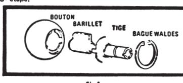
STEP 1 - Insert Cylinder into outside knob, note that cylinder can only be oriented in knob one way.
STEP 2 - Follow correct instructions under appropriate lock function,
A) For 451 & 457 Functions
- Insert plug driver into back of cylinder so that plug driver and plug are concentric. Insert plug driver into back of cylinder so that plug driver and plug are concentric. If set knob shank down over plug driver, Note: If knob shank does not seat flush, then the plug driver is not located correctly. If using Waldes Tru-arc pliers insert Waldes retaining ring. Be sure that beveled edge of retaining ring faces away from knob and that ring is properly seated in the groove. If Go to Step 3. If or other thanks are the plug driver and plug are concentric. If of the plug driver into back of cylinder so that plug driver and plug are concentric. If of the plug are concentric. If of the plug are concentric. If of the plug are concentric. If of the plug are concentric. If of the plug are concentric. If of the plug are concentric. If of the plug are concentric. If of the plug are concentric. If of the plug are concentric. If of the plug are concentric. If of the plug are concentric. If of the plug are concentric. If of the plug are concentric. If of the plug are concentric. If of the plug are concentric. If of the plug are concentric. If of the plug are concentric. If of the plug are concentric. If of the plug are concentric. If of the plug are concentric. If of the plug are concentric. If of the plug are concentric. If of the plug are concentric. If of the plug are concentric. If of the plug are concentric. If of the plug are concentric. If of the plug are concentric. If of the plug are concentric. If of the plug are concentric. If of the plug are concentric. If of the plug are concentric. If of the plug are concentric. If of the plug are concentric. If of the plug are concentric. If of the plug are concentric. If of the plug are concentric. If of the plug are concentric. If of the plug are concentric. If of the plug are concentric. If of the plug are concentric. If of the plug are concentric. If of the plug are concentric. If of the plug are concentric. If of the plug are concentric. If of the plug are concentric. If
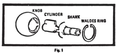
- Insert lazy cam into back of cylinder so that lazy cam and plug are concentric. Set knob shank down over lazy cam. If knob shank does not seat flush, then the lazy cam is not located correctly. Note: The knob shank only locates in one position over the lazy cam. Follow Step 2 A iii.
- Set spring down inside knob shank. Go to Step 3..
-
STEP3 A) FOR LEFT HAND KNOB & CHASSIS ASSEMBLY HOLD ASSEMBLY IN AN UPRIGHT
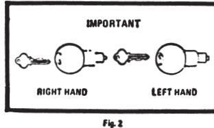
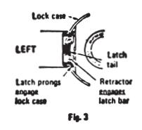
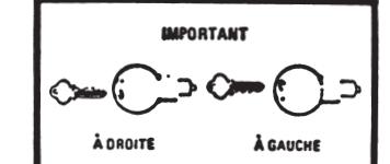
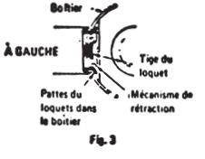
- Position chassis so that latch prongs are facing to the left. (Fig. 3) Isert knob and cylinder assembly so that CUTS IN KEY ARE FACING DOWN, then push until knob snaps in (Fig. 2). Proceed with installation instruction sheet.
- B) FOR RIGHT HAND, KNOB & CHASSIS ASSEMBLY HOLD ASSEMBLY IN AN UPRIGHT FASHION
- Position chassis so that latch prongs are facing to the left. (Fig. 3) Insert Knob and cylinder assembly so that CUTS IN KEY ARE FACING UP, then push until knob snaps in (Fig. 2).
- ion instruction sheet. Proceed with in
FEUILLET D'INSTRUCTIONS POUR L'INSTALLATION DES BARILLETS SERRURES ULTRA ROBUSTES
1º ÉTAPE - Insérer le barillet dans le bouton extérieur. Remarque: Le barillet ne peut être inséré dans le bouton que dans un seul sens.
26 ÉTAPE - Suivre les instructions selon les fonctions convenables.
- A) Pour fonctions 451 et 457 \ni Insérer la broche Indicate the state of the state of the state of the state of the state of the state of the state of the state of the state of the state of the state of the state of the state of the state of the state of the state of the state of the state of the state of the state of the state of the state of the state of the state of the state of the state of the state of the state of the state of the state of the state of the state of the state of the state of the state of the state of the state of the state of the state of the state of the state of the state of the state of the state of the state of the state of the state of the state of the state of the state of the state of the state of the state of the state of the state of the state of the state of the state of the state of the state of the state of the state of the state of the state of the state of the state of the state of the state of the state of the state of the state of the state of the state of the state of the state of the state of the state of the state of the state of the state of the state of the state of the state of the state of the state of the state of the state of the state of the state of the state of the state of the state of the state of the state of the state of the state of the state of the state of the state of the state of the state of the state of the state of the state of the state of the state of the state of the state of the state of the state of the state of the state of the state of the state of the state of the state of the state of the state of the state of the state of the state of the state of the state of the state of the state of the state of the state of the state of the state of the state of the state of the state of the state of the state of the state of the state of the state of the state of the state of the state of the state of the state of the state of the state of the state of the state of the state of the state of the state of the state of the state of the state of the state of the state of the state of the state of the stat
- broche n'est pas bien placée.
- à l'aide de pinces Waldes Tru-Arc, insérer la bague de retenue Waldes. S'assurer que le rebord biseauté de la bague ne soit pas tourné vers le bouton et que la bague repose bien dans la rainure. Passer à la 3e étape.
In our fonction abb Inserer la came libre au dos du barillet de façon à qu'elle solt concentrique avec le rotor. Inserer la tige du bouton sur la came libre. Si la tige du bouton ne repose pas à ras, la came libre n'est pas bien placée. Remarque: La tige du bouton ne s'insère que d'une seule façon sur la came libre. Illi Suivre l'étape 2 A - III.
Repousser le ressort à l'Intérieur de la tige du bouton. Passer à la 3º étape.
3º ÉTAPE - A) POUR LES BOUTONS ET CHÀSSIS INSTALLÉS À GAUCHE - TENIR L'ENSEMBLE À L'ENDROIT
- Placer le châssis de sorte que les agrafes du loquet solent tournées vers la gauche (Fig. 3). Insérer le bouton et le barillet de sorte que les DENTS DE LA CLÉ SOIENT TOURNÉES VERS LE BAS, puis pousser le bouton jusqu'à ce qu'il s'embo îte (Fig. 2). Poursuivre l'installation selon le feuillet d'instructions.
- 8) POUR BOUTONS ET CHASSIS INSTALLÉS À DROITE TENIR L'ENSEMBLE À L'ENDROIT.
- Placer le châssis de sorte que les agrafes du loquet soient tournées vers la gauche (Fig. 3). Insérer le bouton et le barillet de sorte que les DENTS DE LA CLÉ SOIENT TOURNÉES VERS LE HAUT, puis pousser le bouton jusqu'à ce qu'il s'embolte (Fig. 2). Poursuivre l'installation selon le feuillet d'instructions.
Form 173LC 12/18
08/2018