Corbin Russwin FE5400S(A) Series 3-Point Exit Devices Installation Instructions_FM329
Open the original PDF document
View PDFInstallation Instructions
FE5400S(A) Series 3 Point Exit Devices
ASSA ABLOY, the global leader in door opening solutions

ASSA ABLOY
In U.S.: Corbin Russwin, Inc. 225 Episcopal Road Berlin, CT 06037 USA www.corbinrusswin.com
In Canada: ASSA ABLOY Door Security Solutions Canada 160 Four Valley Drive Vaughan, Ontario, Canada L4K4T9 www.assaabloy.ca
Technical Product Support: Phone: 888-607-5703
General Information

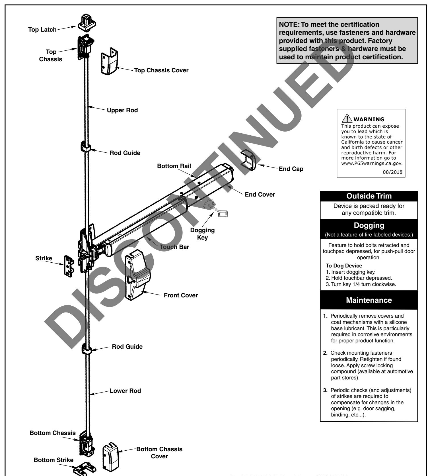
This device is intended to be part of an integrated door, frame and hardware assembly ULapproved for both FEMA 361 and ICC 500 guidelines for out swing doors. This instruction sheet will take you through the necessary steps to install this device.
ASSA ABLOY
| Step # | Table of Contents | Page |
|---|---|---|
| 1 | Check Before Starting | 2 |
| 2 | Tools Required | 2 |
| 3 | Mark Door | 3 |
| 4 | Size Device | 3 |
| 5 | Install Device | 4 |
| 6 | Install Device Strike | 5-6 |
| 7 | Prepare Top Rod | 7 |
| 8 | Install Top Chassis | 8 |
| 9 | Install Bottom Chassis | 9 |
| 10 | Install Top Latch | 10 |
| 11 | Install Bottom Strike | 10 |
| 12 | Install Covers | 11 |
| Appendix A Door Template | 12 | |
| Appendix B Top Frame Template | 13 | |
| Appendix C Plastic Door Template | 14 |
Step 1: Check Before Starting
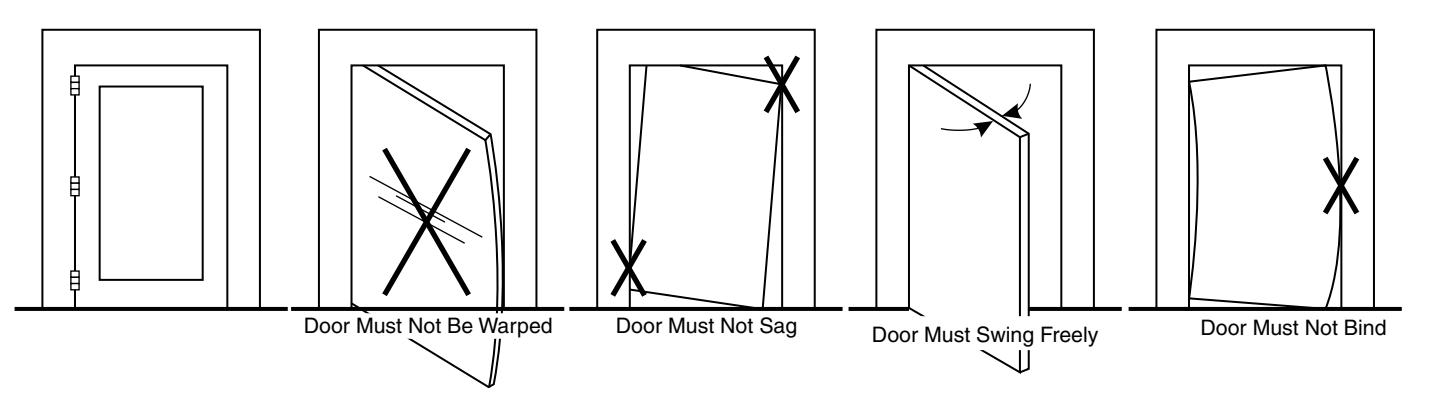
Check to assure that the Top and Bottom latch openings in the frame align with the vertical centerline location for the top and bottom chassis centerline location (refer to page 3 "Mark Door", and Appendix B).
Step 2: Tools Required
Measuring Tape - Power Drill – Level – Square – Center Punch or Center Drill - Hacksaw or any power cutter (to cut rail if necessary) – Screwdrivers (Phillips #2 and #3), Allen Head Hex Wrenches (5/32", 1/8"), Drills (3/8", 1/4", 5/16", 7/16"), Drills and Taps (13/64" or #7 Drill and 1/4"-20 Tap), (11/64" or #16 Drill and #12-24 Tap), (5/32" or #25 Drill and #10-24 Tap).
Step 3: Mark Door

ASSA ABLOY
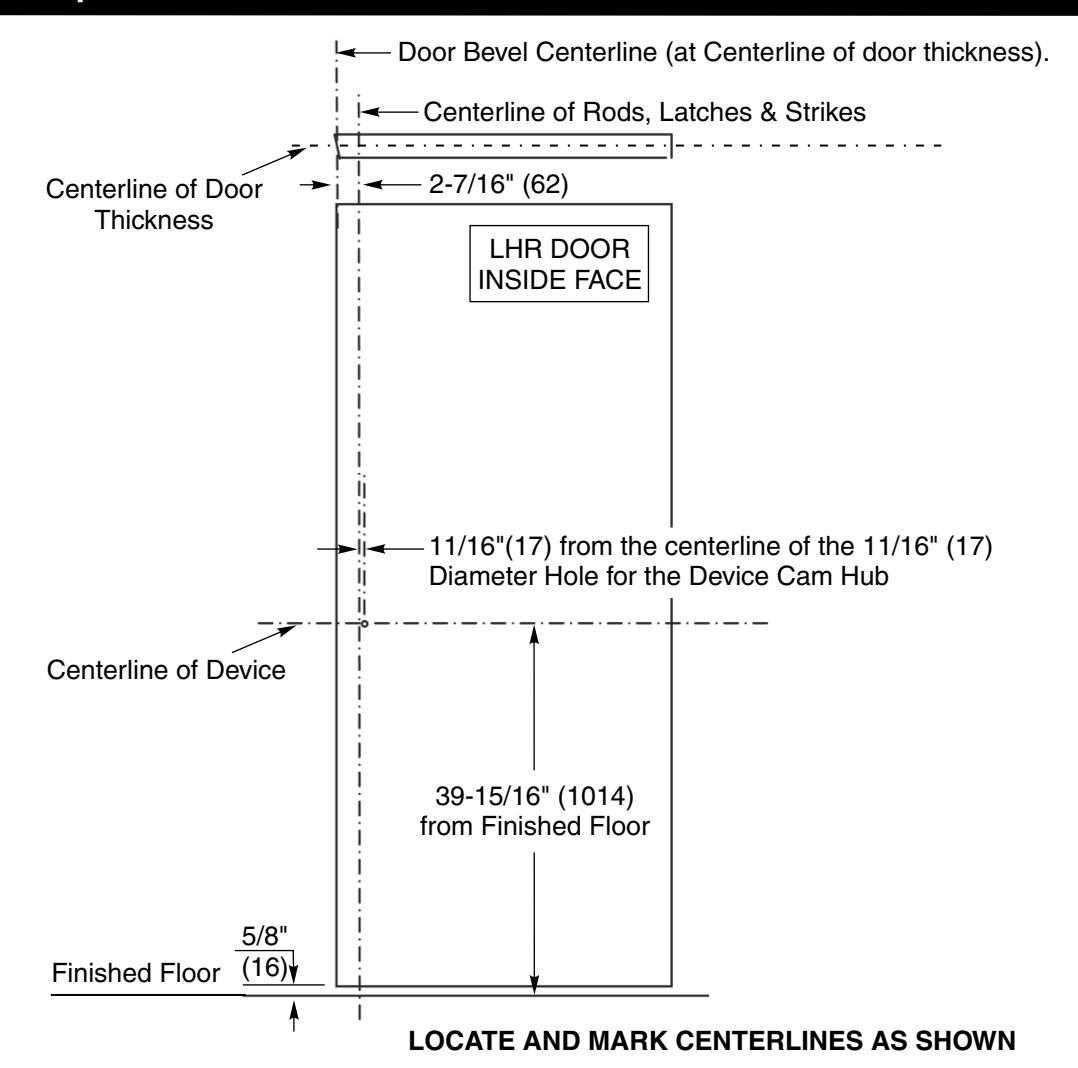
The accuracy of marking the vertical and horizontal centerlines will aid in the installation and operation of the device. A plastic template and block strike are provided to aid in marking these centerlines. See Appendix C page 14.
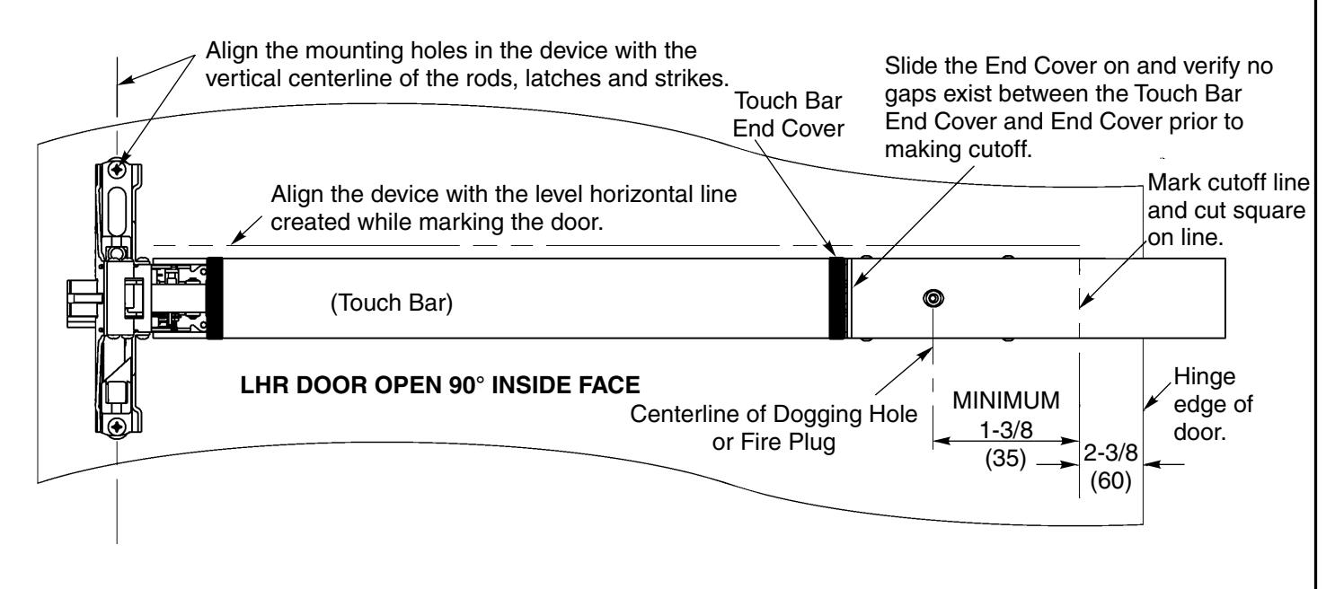
Step 4: Size Device (If necessary)
Step 5: Install Device

ASSA ABLOY When preparing to install device, be prepared to prop the door open during the installation process.
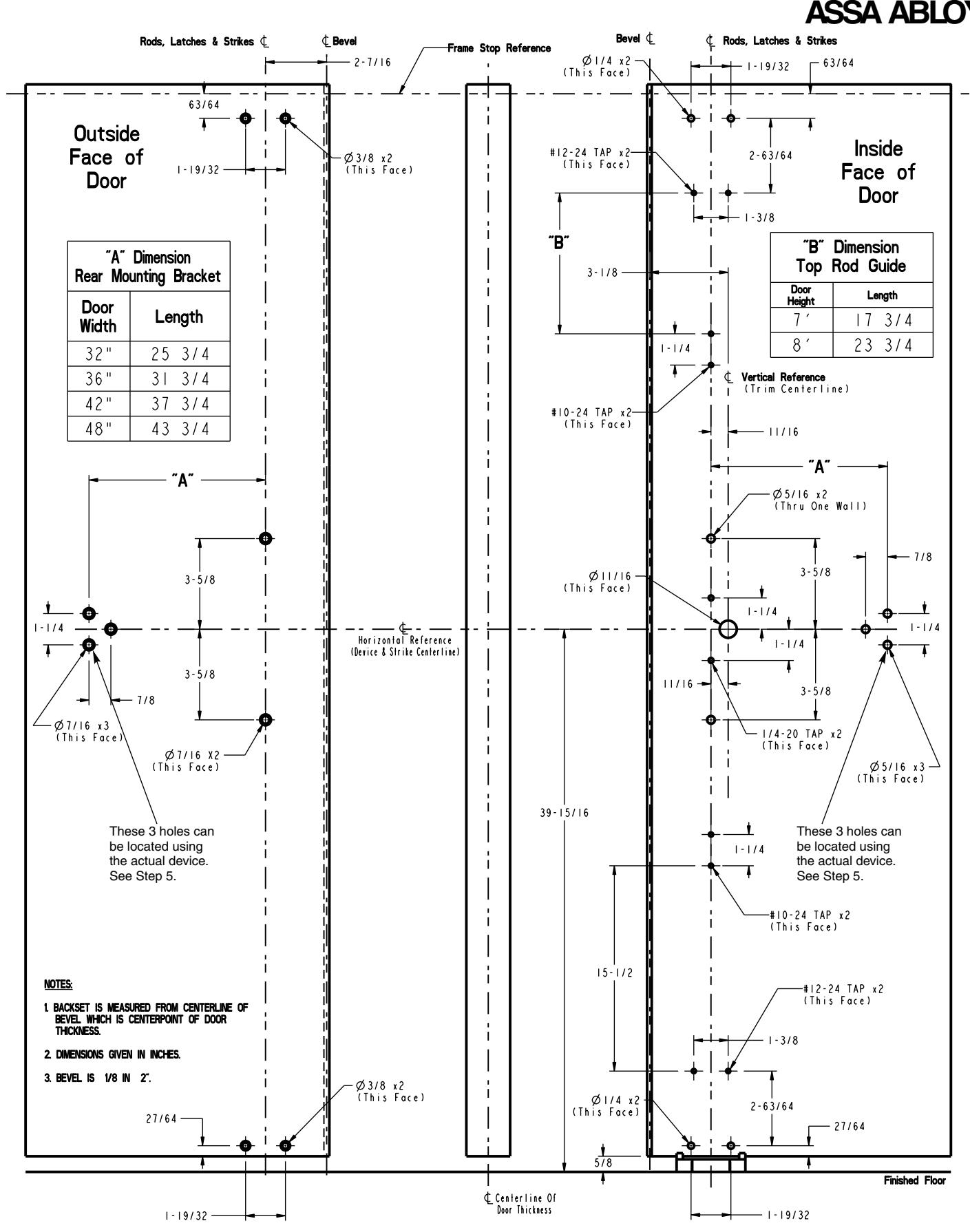
Refer to Appendix A to assure all the holes are in the correct location. Insert two sexnuts into the door from the outside. Align the interlock bracket and device as shown and hand tighten top and bottom 1/4 -20 by 1-1/4" long pan head screws. Hand tighten two 1/4 - 20 by 1" flat head screws into the door. This will require moving the slide to allow the screws to be inserted into the holes with the countersinks. These screws should not be tightened at this time since the interlock bracket will require finer adjustment in step 6.
With the latchhead loosely in place, level the device and mark the position of the 3 holes for the hinge end of the device. Prepare the door per the template (Appendix A).
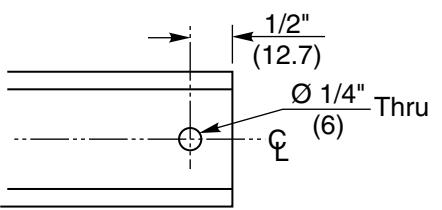
NOTE: If the device has been sized in the field, a 1/4" (6) diameter thru hole will need to be drilled so that the center sexnut and fastener can be used to secure the end of the device to the door.
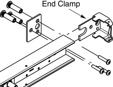
Insert 3 sexnuts into the door from the outside, place the end clamp into the space between the rail and carrier, align the end clamp shim and the end clamp of the device then insert and hand tighten the 3 pan head screws to hold the end clamp and shim of the device to the door.
If device is furnished with the trim, the two sexnuts for the latchhead will not be used. The outside trim studs will be used to thru bolt the device to the trim. If trim is furnished, it will be supplied with two more 1/4 -20 by 1- 1/4" oval head screws that will be required for thru bolting the trim. These will be used in the two slots of the interlock bracket that are not under the latchhead. Refer to the trim template for hole placement for the 2 additional holes required.
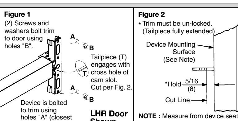
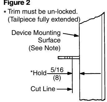
(door face or shim surface).
If furnished with trim, assure that the spindle from the trim is engaged with the hub on the latchhead.
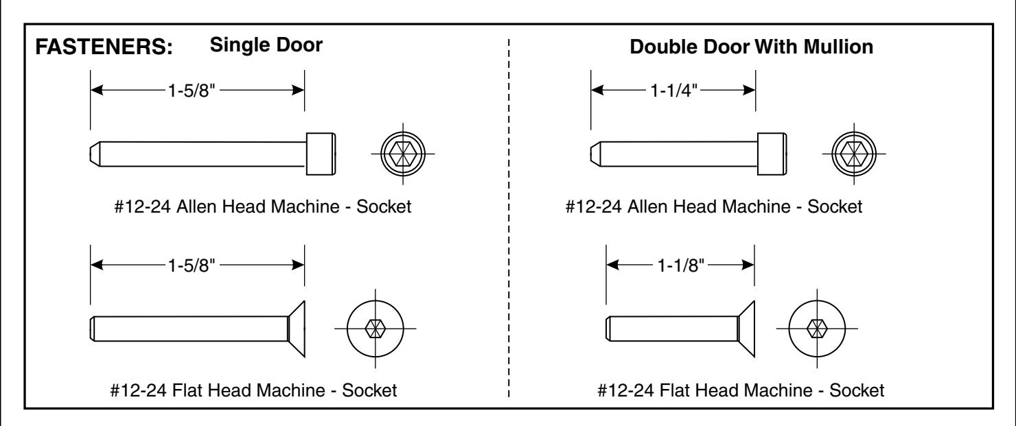
FASTENERS:
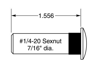
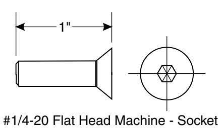
to door lock edge).
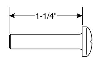

#1/4-20 Pan Head Machine - Phillips
Step 6: Install Device Strike

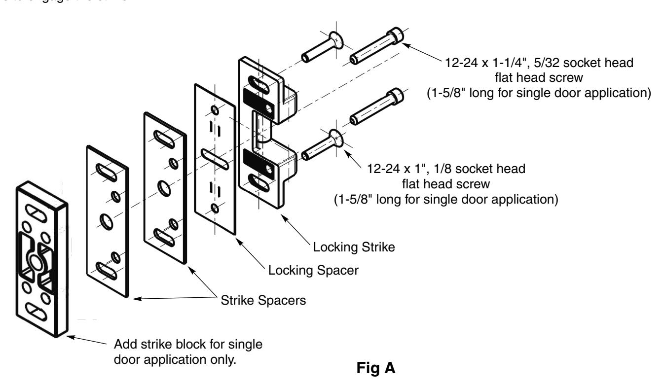
To install the device strike (Fig. A), check to assure the device is level.
ASSA ABLOY
Position the strike so that it is centered in relation to the SecureBolt.
Add spacers so that you will achieve the clearance shown in (Fig. B) on the next page, as well as allow the 3 interlock bracket tabs to engage the strike.
Step 6: Install Device Strike (continued)

ASSA ABLOY
The interlock bracket does have some side to side adjustability that will allow a final adjustment after clearance between the strike and latch head is achieved. This adjustability will require the 4 latch head fasteners to be loosened allowing the interlock bracket to slide into the proper engagement with the strike. Mark the door frame to establish the vertical position of the strike. Its centerline should be on the same centerline as the device.
With the door in the closed position, adjust the strike's position so that when the door is closed, the SecureBolt will be just touching the roller of the strike. This will allow the Securebolt to retract freely when the door is closed. Using the top and bottom slots of the strike (Fig C) center your punch in the middle of the slot and mark the two locations for the 12-24 x 1" Flat Head screws for the strike. Drill and tap these two locations. DO NOT DRILL AND TAP the other two screw locations at this time. Recheck the alignment to the centerline of the device.
Reassemble the strike assembly and finger tighten the flat head screws using a 1/8" allen wrench so that final adjustments can be made. Check to assure you have the proper clearance between the strike and the latch head, the interlock bracket is engaged with the strike and the SecureBolt is not pressing against the roller of the strike. When you have made all these adjustments you may tighten the mounting screws so that the device is securely fastened to the door. Retract the SecureBolt, open the door. Using the strike as a drill guide drill thru the Locking spacer and let your drill mark the two locations for the 12-24 x 1-1/4" 5/32 Socket Head Cap Screws. Remove the strike assembly and drill and tap these two locations. Reassemble the strike assembly and secure it to the frame. Recheck the clearances to assure no further adjustments need to be made.
Check the operation of the device to assure that the strike is aligned properly with the device.
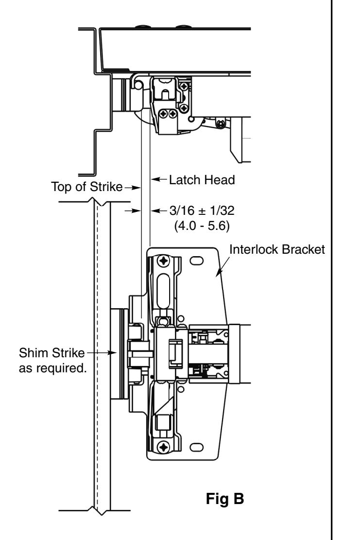
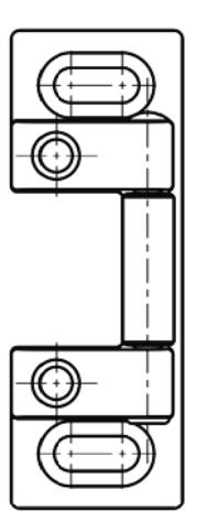
Fig C
Step 7: Prepare Top Rod

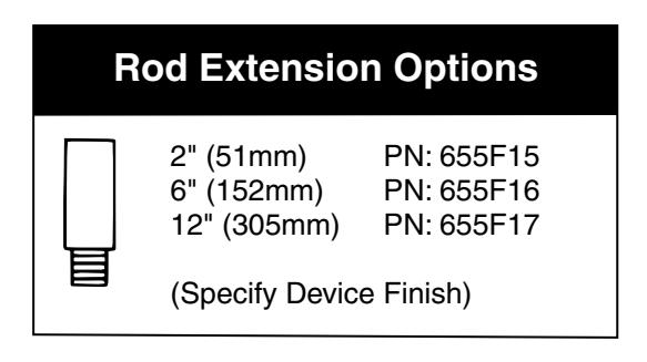
Product comes with the top rod for a 7 foot (84") high opening. If your opening is less, the top rod will need to be shortened. If your opening is more, than an extension will be required and adjustment may or may not be necessary.
ASSA ABLOY
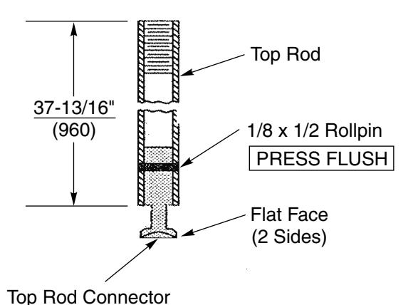
Example of opening less than 84" (using 80" as example):
Subtract your opening from 84" and cut off the necessary amount. 84" minus 80" = 4" (shorten rod by 4")
Example of opening more than 84" (actual opening 88"):
Subtract 84" from the size of your opening. 88" minus 84" = 4" (you need a rod that is 4" longer) In this case you will need a 6" rod extension, and you will need to cut 2" off the bottom of the top rod (the end with the hole for the roll pin). Rod extensions are always added to the top of the rod where it meets the top chassis.
To Lengthen Rods
- Use Rod Extension(s) to extend Rod to length needed or longer (2", 6", or 12" Rod Extensions available).
- Cut excess length from the end of the top rod with the rollpin hole.
To Cut Top Rods
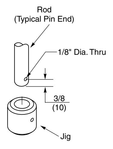
- Cut from end with pin hole. NEVER CUT THREADED END.
- Press Jig until it bottoms over Rod.
- Drill 1/8" dia. hole thru, 3/8" (10) from the end of the shortened top rod. Use jug provided to assure accurate distance.
Step 8: Install Top Chassis

Prepare the top of the door per the door template Appendix A. Check alignment of the top latch location in the frame to assure it lines up with the Top Chassis pusher.
ASSA ABLOY
Insert two 3/8" dia. sexnut into the holes on the outside of the door.
Pusher
Screw the upper rod (approximately 1/2 of the way) onto the top chassis.
Position the shim and Top Chassis so that the mounting holes line up with the holes in the door. Insert and finger tighten the 4 mounting screws provided. Note that the two flat head security screws are for the lower positions.
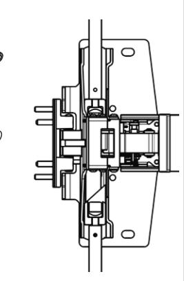
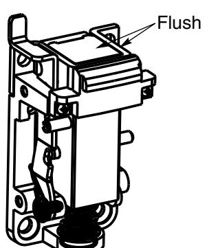
Depress the touchbar and slide the top rod connector into the slot on the latch head slide. With the touchbar depressed the top slide pusher should be flush with the top reinforcement. If adjustment is necessary the rod can be rotated clockwise to shorten it and counterclockwise to lengthen it.
Install the rod guide for the upper rod per the template in Appendix A.
Step 9: Install Bottom Chassis
Corbin 78° Russwin 78°
Prepare the BOTTOM of the door per the door template Appendix A. Check alignment of the bottom strike location in the frame to assure it lines up with the Bottom Chassis.
ASSA ABLOY
Insert two 3/8" dia. sexnuts into the holes on the outside of the door.
Screw the bottom rod (approximately 1/2 of the way) onto the bottom chassis.
Position the shim and Bottom Chassis so that the mounting holes line up with the holes in the door. Insert and finger tighten the 4 mounting screws provided. Note that the two flat head security screws are for the top two positions.
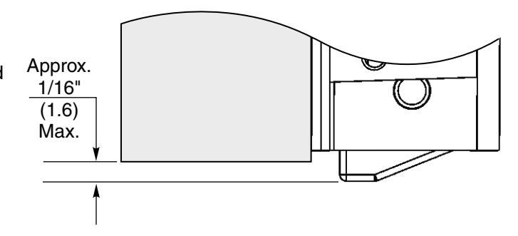
Depress the touchbar and insert the bottom rod connector into the slot on the latch head slide. The bottom bolt should be retracted so that it only projects 1/16" below the bottom of the door in the latch hold back mode. If adjustment is necessary the rod can be rotated clockwise to shorten it and counterclockwise to lengthen it.
Install the rod guide for the bottom rod per the template in Appendix A.

Step 10: Install Top Latch
Corbin 78° Russwin 78°
Check the alignment of the top latch location on the frame to assure it will line up properly with Top Chassis on door. The pusher in the top chassis is designed to push the top latch up when the touchbar is depressed.
ASSA ABLOY
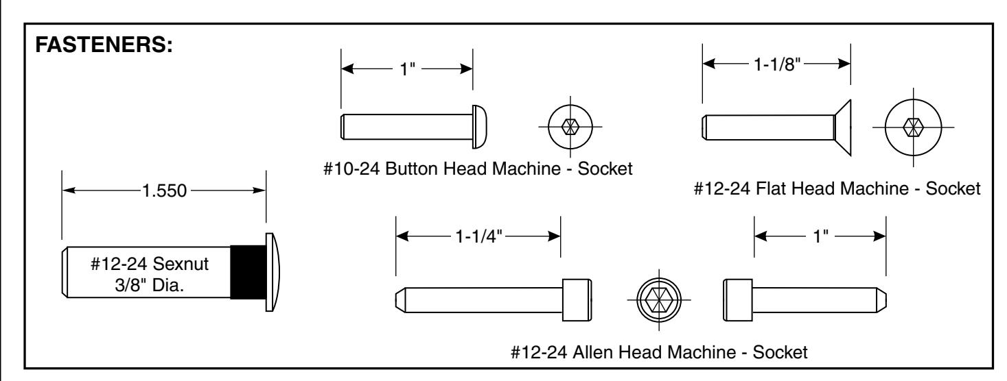
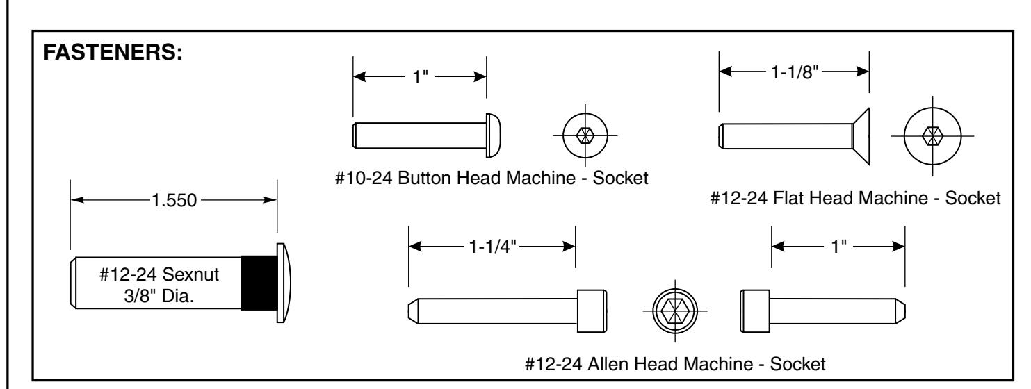
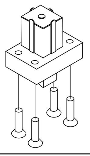
Install the top latch to the frame using the 4, 1/4-20 by 1" Flat Head Allen Socket Head (5/32" Hex Key) Cap Screws provided. The 5/32 hex key has been provided with the device.
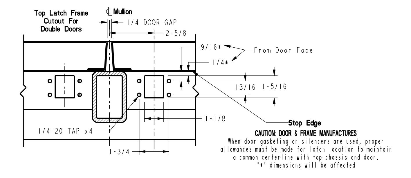
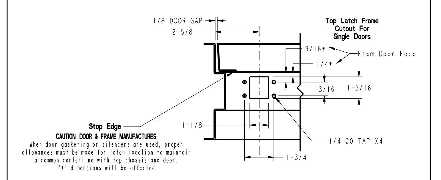
If the frame has not been prepared for installation refer to Appendix B page 13 for preparing the frame.
FASTENERS:
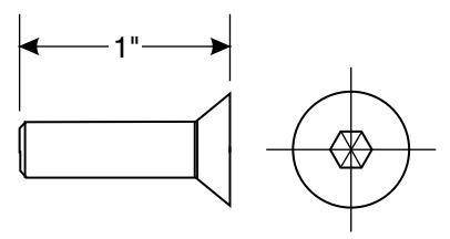
#1/4-20 Flat Head Machine - Allen Socket Head
<u>5/8"</u> (16)
Finished Floor
Step 11: Install Bottom Strike
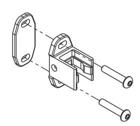
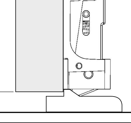
Mount the bottom strike as illustrated in the template (Appendix B). The two tabs on the bottom of the strike must come in contact with the inside face of the door for proper engagement.
FASTENERS:
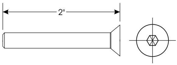
#1/4-20 Flat Head Machine - Socket
Step 12: Install Covers

Check to assure all latches are working properly before the covers are installed.
ASSA ABLOY
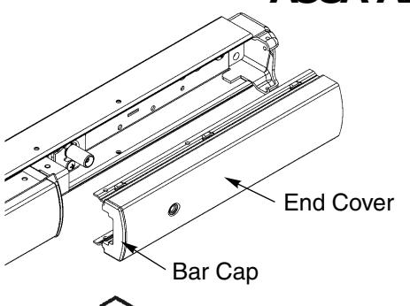
To install the end cover, position the bar cap into the side facing the touchbar and place the end cover's lower edge into position on the rail. Rotate the upper edge on the end cover up and snap it into the rail. The holes for the end cover will line up with the fastener holes in the rail. Secure the end cover with (4) #8 by 1/2" fasteners provided. (2 on top and 2 on bottom.)
Place the end cap into position on the end of the rail and secure with the three #8 by 1/4" long fasteners provided.
End Cap
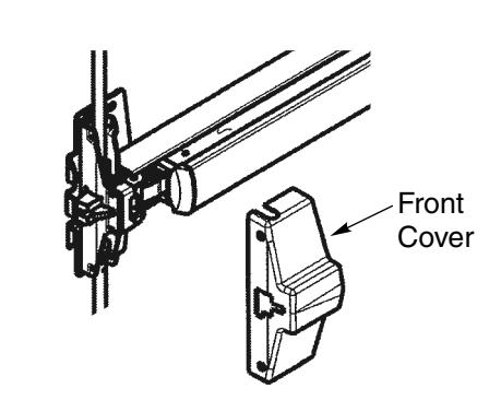
Place the front cover over the latch head assembly and secure with the two #8 by 1/4" long fasteners provided.
Place the top chassis cover over the Top Chassis and secure with the four #8-32 by 5/16" long fasteners provided.

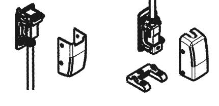
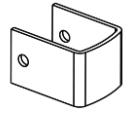
Place the top and bottom Rod Guide Covers over the Rod Guides and fasten each cover with #6 by 3/8" long fasteners provided.
FASTENERS:
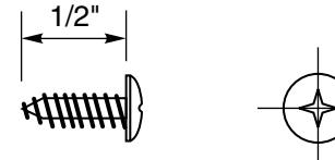
#8 Truss Head Tapping - Phillips - Type A
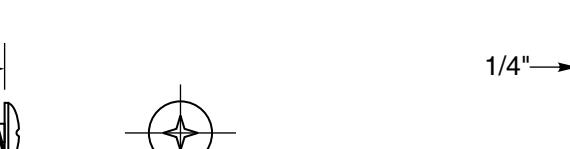
#6 Truss Head Tapping - Phillips - Type A
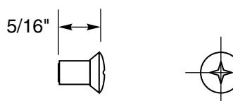
#8-32 Th'd - #6 Oval Head Machine - Phillips
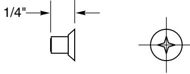
#8-32 Flat Head Undercut Machine - Phillips
Appendix A - Door Template

ASSA ABLOY
Appendix B - Top Frame Template

ASSA ABLOY
Appendix C - Plastic Template

ASSA ABLOY
Centerline Rods.
A plastic template has been provided with the exit device that can be used to accurately mark the vertical centerline that will be used to locate the vertical rods. top and bottom latches and the rim device to the door.
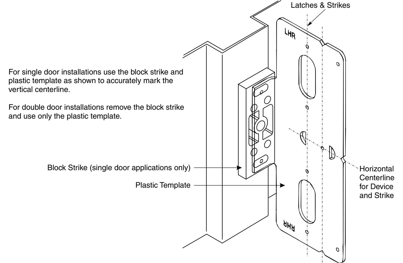
After marking the vertical centerline swing the door to the closed position and visually check to assure that the vertical centerline of the rods, latches & strikes will align with the center of the cut out for the top latch in the frame.
Centerline of 11/16" diameter hole for the device cam hub.